
Related Manuals for Amprobe WT-20


Summary of Contents for Amprobe WT-20
- Page 1 WT-20 Conductivity TDS Meter Users Manual • Mode d’emploi • Bedienungshandbuch • Manual d’Uso • Manual de uso...
- Page 2 WT-20 Conductivity TDS Meter Users Manual July 2009, Rev.1 ©2009 Amprobe Test Tools. All rights reserved. Printed in China...
- Page 3 To obtain service during the warranty period, return the product with proof of purchase to an authorized Amprobe Test Tools Service Center or to an Amprobe dealer or distributor. See Repair Section for details. THIS WARRANTY IS YOUR ONLY REMEDY.
- Page 4 Non-Warranty Repairs and Replacement – US and Canada Non-warranty repairs in the United States and Canada should be sent to a Amprobe® Test Tools Service Center. Call Amprobe® Test Tools or inquire at your point of purchase for current repair and replacement rates.
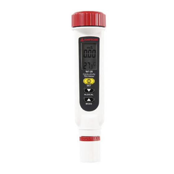
- Page 5 WT-20 Conductivity TDS Meter 1) Battery Cover 2) Lcd Display 3) Power / Set Key 4) Hld / Cal / Down Key 5) Mode / Up Key 6) Electrode Cover 7) Conductivity Reading (unit: uS or mS ) or TDS...
-
Page 6: Table Of Contents
CONTENTS SYMBOLS ................2 UNPACKING AND INSPECTION ........2 INTRODUCTION ..............3 Features ................ 3 OPERATION ............... 3 Auto Power Off ............4 Setup ................5 Calibration Mode ............7 Conductivity Calibration ..........7 TDS Calibration ............9 SPECIFICATION ..............10 MAINTENANCE AND REPAIR ........... -
Page 7: Symbols
That may cause inaccurate reading. • Do not operate the meter in flammable liquid. UNPACKING AND INSPECTION Your shipping carton should include: WT-20 meter LR44 battery Manual If any of the items are damaged or missing, return the complete package to the place of purchase for an... -
Page 8: Introduction
4. Set the temperature coefficient to the right value. WT-20 is factory set to 2.1% per °C. if needed, see P1.3 to set the temperature coefficient. 5. Select the normalization temperature. WT-20 is factory set to 25 °C. -
Page 9: Auto Power Off
7. Dip the probe into the sample container. Make sure no air bubbles trapped in the slot of the probe. To remove air bubbles, give the probe a gentle stir. Making sure the electrode tip is submerged when you stir it. 8. -
Page 10: Setup
Setup The advanced setup mode lets you customize your meter. 4 types parameter are available. P1.0: temperature parameter setting (t) P1.1: Change temperature unit (tUt) P1.2: Normalization temp.(tnr) P1.3: Temp. Coefficient (tCo) P2.0: TDS factor setting P2.1: Setting TDS factor (tds) P3.0: Reset meter (rSt) P3.1: Reset P4.0: Review Calibration Info. - Page 11 P1.3: Temp. Coefficient (tCo) In temp. coefficient adjustment, press “q“or “p“ to change the temperature coefficient from 0.0 to 4.0. Press “SET“ to confirm or press “SET“ more than 2 sec to return to P1.0 without confirming. P2.1: Setting TDS factor(tds): In P2.0, press “SET“...
-
Page 12: Calibration Mode
Calibration Mode (CAL) Selecting a calibration standard For best results, select a conductivity or TDS standard near the sample value you are measuring. Alternatively, use a calibration solution value which is approximate 2/3 of the full scale of the measurement range you plan to use. - Page 13 6. Dip the rinsed probe into the second container. Tap probe on the bottom of container to remove air bubbles. Wait about 15 mins to make the probe stabilize to the solution temperature. 7. Press “CAL“ more than 2 seconds to begin calibration.
-
Page 14: Tds Calibration
TDS Calibration Option1: Using TDS standards 1. Insert the probe into demineralized or distilled water for about 30 minutes to rinse the probe 2. Select the TDS standard for calibration. The factory default setting of the TDS conversion factor is 0.50. You can improve the calibration accuracy by setting the TDS factor before starting the calibration. -
Page 15: Specification
SPECIFICATION Range : 0~1999uS/0~1999ppm or 0~19.99mS/0~19.99ppt Resolution : 1uS/ppm or 0.01mS/ppt Accuracy : 1% Full Scale±1digit TDS factor : 0.40~1.00 Calibration Standard : (0.2~1) * Full Scale Range ATC : 0~50°C Temperature Accuracy : ±0.5°C Temp. Coefficient : 0~4.0% per degree C Normalization Temp. -
Page 16: Maintenance And Repair
MAINTENANCE AND REPAIR If there appears to be a malfunction during the operation of the meter, the following steps should be performed in order to isolate the cause of the problem. 1. Check the battery. Replace the battery immediately when the “ ” symbol appears on the LCD. -
Page 17: Battery Replacement
BATTERY REPLACEMENT 1. Turn off the meter and loose the battery cover in counter-clockwise direction. 2. Replace the old batteries with four new LR44 button cells. 3. Put back the battery cover and turn it tightly. the Red LED Low Battery indicator illuminates. The batteries should be replaced as quickly as possible. -
Page 18: Trouble Shooting
TROUBLE SHOOTING Power On But No Display • Make sure you press power key more than 100 mS. • Check the battery conditions and replace if necessary • Move batteries away for one minute and then re-install. Display Disappear • Check whether the low battery icon is appeared before the display is off. - Page 19 “E03“ Conductivity value is over the range limit (19.99mS) or meter is damaged. • Put the meter in standard solution. If E03 still appears, send back for repair. “E04“ Caused by temp. reading error • Refer to error code of temp. After solving the error of temp, E04 will disappear.
-
Page 20: Appendix A
Appendix A: Conductivity to TDS Conversion Factors TDS KCL TDS (NaCL) TDS (442) Conductivity at 25 °C Factor Factor Factor 23μS 11.6 0.5043 10.7 0.4652 14.74 0.6409 84μS 40.38 0.4807 38.04 0.4529 50.5 0.6012 447μS 225.6 0.5047 215.5 0.4822 0.6712 1413μS 744.7 0.527... -
Page 21: Appendix C
It is mandatory to always associate the temperature together with a conductivity result. If no temperature correction is applied, the conductivity is the value taken at measurement temperature. The WT-20 use linear temperature correction. - Page 22 Linear temperature correction: In moderately and highly conductive solutions, temperature correction can be based on a linear equation involving a temperature coefficient ( ). The coefficient is usually expressed as a conductivity variation in % / °C. Linear temperature correction is used, e.g. for saline solutions, acids and leaching solutions.
- Page 23 T2 should be selected as a typical sample temperature and should be approximately 10°C different from T1. The temperature coefficients of the following electrolytes generally fall into the ranges shown below: Acids: 1.0 - 1.6% / °C Bases: 1.8 - 2.2% / °C Salts: 2.2 - 3.0% / °C Drinking water: 2.0% / °C Ultrapure water: 5.2% / °C...
Need help?
Do you have a question about the WT-20 and is the answer not in the manual?
Questions and answers