
Related Manuals for F&U PAH-1218


Summary of Contents for F&U PAH-1218
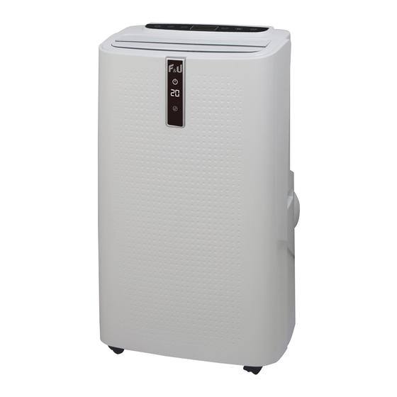
- Page 1 LOCAL AIR CONDITIONER PAH-1218 Instructions Manual Read and save these instructions...
-
Page 2: Table Of Contents
Page:2/20 Content I. Attention Matters………………………………………………………….……………………………………..3 II. Features and Components………………………………………………………………………………………4 III. Control Setting………………………………………………………………………………………….….……5 IV. Protection function……………………………………………………………………………...………………6 V. Installation and adjustment……………………………………………………………………………..………7 VI. Drainage Instructions……………………………………………………………………………………………9 VII. Maintenance……………………………………………..…………………………………….………………10 VIII. Out-of-season save……………………………………………………………………………………………10 IX. Troubleshooting…………………..………………………...……………………………………………..……11 Addendum………………...………………………………..…………………………………………….………11 Please read these instructions before use and repair. The drawings provided in this manual may not be the same as the physical objects. Please refer to the physical objects. -
Page 3: Attention Matters
Page:3/20 I. Attention Matters Warnings: 1. Do not use means to accelerate the defrosting process or to clean, other than those recommended by the manufacturer. 2. The appliance shall be stored in a room without continuously operating ignition sources (for example: open flames, an operating gas appliance or an operating electric heater.) 3. -
Page 4: Features And Components
Page:4/20 When moving the machine, make sure that it is in an upright position. The machine should stay away from gasoline, flammable gas, stoves and other heat sources. Don't disassemble, overhaul and modify the machine arbitrarily, otherwise it will cause a machine malfunction or even bring harm to persons and properties. - Page 5 Page:5/20 Air filtration capability. Timing switch function. Protection function of automatically restarting the compressor after three minutes, a variety of other protection functions. Max operation temperature for the air conditioner Cooling: 35/24℃; heating:20/12 ℃; Temperature operation range: 7-35℃. 2、...
-
Page 6: Control Setting
Page:6/20 Exhaust Pipe Assembly Window Sealing Plate Assembly III. Control Setting 1. Control panel operation instructions 1 ) operation interface : ① Display window ② Remote control receiver ③ Water full indicator 1: when the machine is powered on for the first time, the buzzer will sound, and then the machine will get into standby status. - Page 7 Page:7/20 operate as follows: While setting temperature, press up key or down key to select the required temperature (not available in fan or dehumidification mode). While setting timing value, press up key or down key to select the required timing value. Simultaneously press both keys to switch between Celsius (℃) and Fahrenheit (℉).
-
Page 8: Protection Function
Page:8/20 Instructions of key operation of the remote control are as follows: 1. Power: Press key to turn ON / OFF the machine. 2. Mode: press key to switch between cooling, dehumidification, fan and heating (single cold with no such function) mode. 3. - Page 9 Page:9/20 1.1 Install the heat pipe assembly (as shown in Fig.1) Figure 1 1)take out the outer connector assembly and the exhaust pipe assembly, and remove the plastic bags; 2)insert the heat pipe assembly (the end of the exhaust joint) into the back panel vent slot (push to the left) and complete the assembly (as shown in figure 1).
-
Page 10: Drainage Instructions
Page:10/20 Figure4 2. Elongate the exhaust pipe and snap the flat end of the exhaust pipe joints into the hole of the window sealing plate assembly (as shown in Fig.5 and Fig.6) . Notes : Τhe flat end of the exhaust pipe joints must be snapped into place. ... -
Page 11: Maintenance
Page:11/20 bottom of the body. 2) Place the water container below the side water outlet behind the body. 3) Unscrew the drainage cover and unplug the water plug, the water will automatically flow into the water container. Notes: 1)Keep the drainage cover and the water plug properly. 2)During drainage, the body can be tilted slightly backwards. - Page 12 Page:12/20 3.Clean the upper filter screen frame 1)Unscrew one screw fixed by EVA filter net and back shell with screwdriver, and take out EVA filter net. 2)Put the EVA filter screen into warm water with neutral detergent (about 40℃ / 104℉) and dry it in the shade after rinsing clean.
- Page 13 Page:13/20 material. 4) Checking for presence of refrigerant The area shall be checked with an appropriate refrigerant detector prior to and during work, to ensure the technician is aware of potentially flammable atmospheres. Ensure that the leak detection equipment being used is suitable for use with flammable refrigerants, i.e. non-sparking, adequately sealed or intrinsically safe.
- Page 14 Page:14/20 Initial safety checks shall include: • That capacitors are discharged: this shall be done in a safe manner to avoid possibility of sparking; • That there no live electrical components and wiring are exposed while charging, recovering or purging the system;...
- Page 15 Page:15/20 for use with most refrigerants but the use of detergents containing chlorine shall be avoided as the chlorine may react with the refrigerant and corrode the copper pipe-work. If a leak is suspected, all naked flames shall be removed / extinguished. If a leakage of refrigerant is found which requires brazing, all of the refrigerant shall be recovered from the system, or isolated (by means of shut off valves) in a part of the system remote from the leak.
- Page 16 Page:16/20 b) Isolate system electrically. c) Before attempting the procedure ensure that: • Mechanical handling equipment is available, if required, for handling refrigerant cylinders; • All personal protective equipment is available and being used correctly; • The recovery process is supervised at all times by a competent person; •...
- Page 17 Page:17/20 Fuse parameters of the machine Type: FSD or 50F Voltage: 250V Current: 3.15 A Unit Storage: 1:Unscrew the drainage cover, unplug the water plug, and discharge the water in the water pan into other water containers or directly tilt the body to discharge the water into other containers. 2:Turn on the machine, adjust it to low-wind ventilation mode, and maintain this state until the drainage pipe becomes dry, so as to keep the inside of the body in a dry state and prevent it from mildewing.
-
Page 18: Troubleshooting
Page:18/20 IX.Troubleshooting Do not repair or disassemble the air conditioning by yourself. Unqualified repair will lead to failure of the warranty card, and may cause damage to users or their properties. Problems Reasons Solutions Turn it on after connecting it to a socket There is no electricity. -
Page 19: Addendum
Page:19/20 X.Addendum Schematic diagram for air conditioning (The specific technical parameters of the machine shall be subject to the nameplate on the product) Capillary Condenser Compressor Evaporator... - Page 20 Page:20/20 NOTICE ABOUT RECYCLING Your product is designed and manufactured with high quality materials and components which can be recycled and reused. This symbol means that electrical and electronic equipment, at their end-of-life, should be disposed of separately from your household waste. Please dispose of this equipment at your local community waste collection/ recycling centre.
Need help?
Do you have a question about the PAH-1218 and is the answer not in the manual?
Questions and answers