Table of Contents
Advertisement
INSTALLATION INSTRUCTIONS
R−410A Single Package Heat Pumps
These instructions must be read and understood completely before attempting installation
DANGER, WARNING, CAUTION, and NOTE
The signal words DANGER, WARNING,
CAUTION, and NOTE are used to identify levels
of hazard seriousness. The signal word DANGER
is only used on product labels to signify an
immediate hazard. The signal words WARNING,
CAUTION, and NOTE will be used on product
labels and throughout this manual and other
manual that may apply to the product.
DANGER − Immediate hazards which will result in
severe personal injury or death.
WARNING −Hazards or unsafe practices which
could result in severe personal injury or death.
CAUTION − Hazards or unsafe practices which
may result in minor personal injury or product or
property damage.
NOTE − Used to highlight suggestions which will
result in enhanced installation, reliability, or
operation.
TABLE OF CONTENTS
. . . . . . . . . . . . . . . . . . . . . . . . . . . . .
. . . . . . . . . . . . . . . . . . . . . . . . . . . .
. . . . . . . . . . . . . . . . . . . . . . . . . . . . . . . . .
. . . . . . . . . . . . . . . . . . . . . . . . . .
. . . . . . . . . . . . . . . . . . . . . . . . . . . . . . . .
. . . . . . . . . . . . . . . . . . . . . . . . . . . . .
. . . . . . . . . . . . . . . . . . . . . . . . . . .
PHD424−60
1 & 3 Phase
Safety Labeling and Signal Words
. . . . . . . . . . . . . . . . .
. . . . . . . . . . . . .
. . . . . . . . . . . . . . . . . . .
. . . . . . . . . . . . . . . . .
. . . . . . . . . . . . . . . . . .
. . . . . . . . . . . . . . . . . . .
. . . . . . . . . . . . . .
. . . . . .
. . . . . . . . . .
. . . . . . . . . .
Signal Words in Manuals
The signal word WARNING is used throughout
this manual in the following manner:
WARNING
!
The signal word CAUTION is used throughout
this manual in the following manner:
CAUTION
!
Signal Words on Product Labeling
Signal words are used in combination with
colors and/or pictures or product labels.
WARNING
!
2
2
PERSONAL INJURY, AND/OR PROPERTY
2
DAMAGE HAZARD
2
Failure to carefully read and follow this warning
could result in equipment malfunction, property
3
damage, personal injury and/or death.
3
Installation or repairs made by unqualified
7
persons could result in equipment malfunction,
8
property damage, personal injury and/or death.
9
The information contained in this manual is
12
intended for use by a qualified service technician
18
familiar with safety procedures and equipped
18
with proper tools and test instruments.
18
Installation must conform with local building
codes and with the national Electrical Code
19
NFPA70 current edition or Canadian Electrical
22
Code part 1 CSA C.22.1.
30
33
518 01 2003 03
7−19−13
Advertisement
Table of Contents

Related Manuals for International comfort products PHD424


Summary of Contents for International comfort products PHD424
-
Page 1: Table Of Contents
INSTALLATION INSTRUCTIONS R−410A Single Package Heat Pumps PHD424−60 1 & 3 Phase These instructions must be read and understood completely before attempting installation Safety Labeling and Signal Words DANGER, WARNING, CAUTION, and NOTE The signal words DANGER, WARNING, Signal Words in Manuals... -
Page 2: Safety Considerations
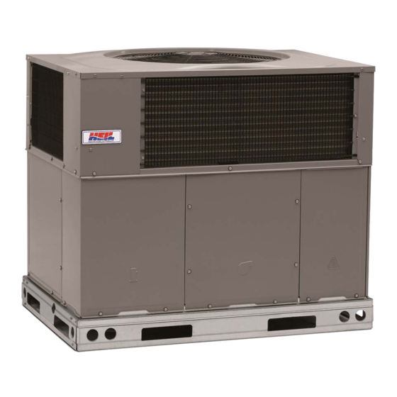
CAUTION Fig. 1 − Unit PHD4 CUT HAZARD Failure to follow this caution may result in personal injury. When removing access panels or performing maintenance functions inside your unit, be aware of sharp sheet metal parts and screws. Although special care is taken to reduce sharp edges to a minimum, be extremely careful and wear appropriate clothing, safety glasses, and gloves when handling parts or reaching into the unit. -
Page 3: Step 3 - Provide Clearances
Slab Mount 1. Application of the lifter to the load, and adjustment of the lifts to adapt to various sizes or kinds of loads. Place the unit on a solid, level pad that is at least 2 in. (51 mm) 2. - Page 4 518 01 2003 03...
- Page 5 518 01 2003 03...
- Page 6 Fig. 4 − Roof Curb Dimensions Dashed lines show cross support location for large basepan units. HVAC unit HVAC unit basepan base rails Sealing Gasket Roofcurb Anchor screw field supplied Wood nailer* Flashing field supplied (field supplied) Roofing material field supplied Cant strip field supplied SMALL/COMMON CURB...
-
Page 7: Step 5 − Install Duct Connections
Fig. 5 − Rigging Weights CAUTION - NOTICE TO RIGGERS PRUDENCE - AVIS AUX MANIPULATEUR ACCESS PANELS MUST BE IN PLACE WHEN RIGGING. PANNEAUX D'ACCES DOIT ÊTRE EN PLACE POUR MANIPULATION. Use top skid as spreader bar. / Utiliser la palette du haut comme barre de répartition DUCTS MINIMUM HEIGHT: 36"... -
Page 8: Step 6 - Provide For Condensate Disposal
Heat resistant duct connector (or sheet metal sleeve) must unconditioned space, and use vapor barrier in accordance extend 24−in. (610 mm) from electric heater element. with latest issue of Sheet Metal and Air Conditioning Contractors National Association (SMACNA) and Air 3. -
Page 9: Step 7 - Install Electrical Connections
Fig. 7 − Condensate Trap CAUTION TRAP OUTLET UNIT COMPONENT DAMAGE HAZARD Failure to follow this caution may result in damage to 1-in. (25 mm) min. the unit being installed. 1. Make all electrical connections in accordance with 2-in. (51 mm) min. NEC NFPA 70 (latest edition) and local electrical codes governing such wiring. - Page 10 2. Connect ground lead to chassis ground connection. Some electric heaters have four control wires (plus common wire). Consult unit wiring diagram and electric heater wiring 3. Locate the black and yellow wires connected to the line diagram for additional details. side of the contactor.
- Page 11 { If using accessory filter rack refer to the filter rack installation instructions for correct filter size and quantity. } For 460 volt units, add 14 lb (6.4 kg) to the weight. Table 2 – Minimum Airflow for Reliable Electric Heater Operation (CFM) SIZE PHD424 PHD430 PHD436 PHD442...
- Page 12 FIG. 12 − CONNECTION WIRING SCHEMATICS 208/230−1−60 518 01 2003 03...
- Page 13 FIG. 13 − LADDER WIRING SCHEMATICS 208/230−1−60 518 01 2003 03...
- Page 14 FIG. 14 − CONNECTION WIRING SCHEMATICS − 208/230−3−60 518 01 2003 03...
- Page 15 FIG. 15 − LADDER WIRING SCHEMATICS − 208/230−3−60 518 01 2003 03...
- Page 16 FIG. 16 − CONNECTION WIRING DIAGRAM 460−3−60 DANGER: ELECTRICAL SHOCK HAZARD DISCONNECT POWER BEFORE SERVICING NOTES: SCHEMATIC 1. IF ANY OF THE ORIGINAL WIRES FURNISHED ARE REPLACED, 2. SEE PRICE PAGES FOR THERMOSTATS. THEY MUST BE REPLACED WITH THE SAME WIRE OR ITS EQUIVALENT. IF USED 460−3−60 3.
- Page 17 FIG. 17 − LADDER WIRING DIAGRAM 460−3−60 DANGER: ELECTRICAL SHOCK HAZARD DISCONNECT POWER BEFORE SERVICING USE COPPER CONDUCTORS ONLY FIELD SUPPLY 460 VAC, 60 HZ, 3PH (IF USED) UNIT COMPONENT ARRANGEMENT OUTDOOR FAN SECTION COMPRESSOR INDOOR FAN CONTROL BOX AREA SECTION SECTION CAP 1...
-
Page 18: Pre−Start−Up
PRE−START−UP START−UP Checking Cooling and Heating Control Operation WARNING Start and check the unit for proper control operation as follows: (1.) Place room thermostat SYSTEM switch or MODE FIRE, EXPLOSION, ELECTRICAL control in OFF position. Observe that blower motor ENVIRONMENTAL SHOCK HAZARD starts when FAN mode is placed in FAN ON Failure to follow this warning could result in personal injury, position and shuts down when FAN MODE switch... -
Page 19: Airflow Adjustments
Checking and Adjusting Refrigerant Charge WARNING The refrigerant system is fully charged with R−410A refrigerant and is tested and factory sealed. ELECTRICAL SHOCK HAZARD NOTE: Adjustment of the refrigerant charge is not required Failure to follow this warning could result in personal unless the unit is suspected of not having the proper R−410A injury or death. - Page 20 4. Remove the vinyl cap off of the desired speed tap wire Table 3 – Color Coding for Indoor Fan Motor Leads (Refer to Table 3 for color coding) for the normal cooling Black = High Speed fan speed and place desired speed tap wire on “HIGH” on Orange = Med−High Speed the interface board.
- Page 21 Fig. 19 − Typical Heat Pump Operation, Cooling Mode Piston Metering Device Fig. 20 − Typical Heat Pump Operation, Heating Mode Piston Metering Device Step 3 — Defrost Control Defrost Quiet Shift The defrost control is a time/temperature control which includes a field−selectable time period (DIP switch 1 and 2 on the board) Quiet Shift is a field−selectable defrost mode, which will eliminate between defrost cycles of 30, 60, 90, or 120 minutes (factory set...
-
Page 22: Maintenance
short defrost cycle will be observed (actual length is dependent outdoor fan for 40 sec. When the Quiet Shift is in OFF position, upon the selected Quiet Shift position). When Quiet Shift switch only a brief 30 sec. cycle will be observed. is in ON position, the length of defrost is 1 minute (30 sec NOTE: Unit will remain in defrost until defrost thermostat... - Page 23 To clean the blower motor and wheel: CAUTION 1. Remove and disassemble blower assembly as follows: a. Remove blower access panel. UNIT OPERATION HAZARD b. Disconnect 5 pin plug and 4 pin plug from indoor Failure to follow this caution may result in improper blower motor.
- Page 24 Table 4 – Dry Coil Air Delivery CFM* − Horizontal Discharge − Unit PHD4 Unit External Static Pressure (in W.C.) PHD4 Motor Speed Wire Color Blue MedLow Pink Medium ...
- Page 25 Table 4 − Dry Coil Air Delivery CFM* − Downflow Discharge − Unit PHD4 Unit Motor Wire External Static Pressure (in W.C.) PHD4 Speed Color Blue WATTS 0.09 0.10 0.10 0.11 1002 WATTS MedLow Pink 0.15 0.17 0.17 0.19 0.20 0.21 0.22 1110...
- Page 26 Table 4 − Dry Coil Air Delivery CFM* − Downflow Discharge − Unit PHD4 Unit Motor Wire External Static Pressure (in W.C.) PHD4 Speed Color 1491 1445 1403 1358 1306 1261 1199 1169 1122 1069 Blue WATTS 0.25 0.26 0.27 0.28 0.30 0.31...
- Page 27 Table 5 – PHD4 Wet Coil Pressure Drop (in. W.C.) STANDARD CFM (S.C.F.M) UNIT SIZE 1000 1100 1200 1300 1400 1500 1600 1700 1800 1900 2000 0.06 0.07 0.08 0.09 0.12 0.15 0.19 0.23 0.27 0.07 0.11 0.18 0.26 0.35 0.04 0.07 0.15...
- Page 28 Fig. 23 − Cooling Charging Table−Subcooling 518 01 2003 03...
- Page 29 Step 3 — Outdoor Fan Fig. 24 − Refrigerant Circuit Keep the condenser fan free from all obstructions to ensure proper cooling operation. Never place articles on top of the unit. Damage to unit may result. 1. Remove 6 screws holding outdoor grille and motor to top cover.
-
Page 30: Troubleshooting
3. Place terry cloth shop towel inside unit immediately under WARNING component(s) to be serviced and prevent lubricant run−offs through the louvered openings in the unit base. EXPLOSION HAZARD 4. Perform required service. 5. Remove and dispose of any oil contaminated material per Failure to follow this warning could result in personal local codes. - Page 31 R−410A QUICK REFERENCE GUIDE S R−410A refrigerant operates at 50−70 percent higher pressures than R−22. Be sure that servicing equipment and replacement components are designed to operate with R−410A R−410A refrigerant cylinders are rose colored. Recovery cylinder service pressure rating must be 400 psig, DOT 4BA400 or DOT BW400. R−410A systems should be charged with liquid refrigerant.
- Page 32 Table 9 – Troubleshooting Chart SYMPTOM CAUSE REMEDY Power failure Call power company Fuse blown or circuit breaker tripped Replace fuse or reset circuit breaker Defective contactor, transformer, or high−pressure, loss− Replace component Compressor and condenser fan will not start. of−charge or low−pressure switch Insufficient line voltage Determine cause and correct...
-
Page 33: Start−Up Checklist
REFRIGERANT DISCHARGE PSIG, LIQUID TEMP{ ( ) VERIFY REFRIGERANT CHARGE USING CHARGING CHARTS * Measured at suction inlet to compressor { Measured at liquid line leaving condenser. 518 01 2003 03 Copyright 2013 International Comfort Products Lewisburg, TN 37091 USA...
Need help?
Do you have a question about the PHD424 and is the answer not in the manual?
Questions and answers