Table of Contents
Advertisement
Quick Links
Installation Instructions
PACKAGED HEAT PUMP UNITS
. . . . . . . . . . . . . . . . . . . . . . . . . . . . . . . . . . . . . . . . . . . . . . .
. . . . . . . . . . . . . . . . . . . . . . . . . . . . . . . . . .
. . . . . . . . . . . . . . . . . . . . . . . . . . . . . . . .
. . . . . . . . . . . . . . . . . . . . . . . . . . . . . .
. . . . . . . . . . . . . . . . . . . . . . . . . . . . . .
. . . . . . . . . . . . . . . . . . . . . . . . . . . . . . . . . . . . . .
. . . . . . . . . . . . . . . . . . . . . . . . . . . . . .
. . . . . . . . . . . . . . . . . . . . . . . . . . . . . . .
. . . . . . . . . . . . . . . . . . . . . . . . . . . . . . . . . . . . . .
. . . . . . . . . . . . . . . . . . . . . . . . .
. . . . . . . . . . . . . . . . . . . . . . . . . . . . . . . . .
. . . . . . . . . . . . . . . . . . . . . . . . . . . . . . . . . . . . . .
Printed in U.S.A.
PHN5 Series
Single Phase
TABLE OF CONTENTS
PAGE
. . . . . . . . . . . . . . . . . . . . . . .
. . . . . . . . . . . . . . . . . . .
. . . . . . . . . . . . . . . . . . . . . . . . .
. . . . . . . . . . . . . . . . . . . . . . . . . .
. . . . . . . . . . . . . . . . . . . . . . .
. . . . . . . . . . . . . . . . . . . . . . . .
. . . . . . . . . . . . . . . . . . . . . . .
. . . . . . . . . . . . . . . . . . . . . .
. . . . . . . . . . . . . . . . . . . . .
. . . . . . . . .
. . . . . . . . . . . . . . . . . . . .
. . . . . . . . . . . . . . . . . . . . . . . .
. . . . . . . . . . .
. . . . . . . . . . . . . . . . . . . . . . . . .
. . . .
. . . . . . . . . . . . . . . . . . . . . .
International Comfort Products, LLC
Lewisburg, TN. 37091
1
2
2
2
2
2
. . . . . . . . . . . . . . . . . . . . . . . . . . . . . . . . . . . . . .
2
3
. . . . . . . . . . . . . . . . . . . . . . . . . . . . . . . . . . . . . . .
3
3
3
3
7
9
9
9
10
10
10
10
10
10
11
14
14
14
14
. . . . . . . . . . . . . . . . . . . . . . . . . .
. . . . . . . . . . . . .
. . . . . . . . . . . . . . . . . . . . .
. . . . . . . . . . . . . . . . . . . . . . . . . . . . . . . . .
. . . . . . . . . . . . . . . . . . . . . . . . . . . . . . . . . . .
. . . . . . . . . . . . . . . . . . . . . . . . . . . . . . . . .
. . . . . . . . . . . . . . . . . . . . . . . . .
. . . . . . . . . . . . . . . . . . . . . . . . . . . . . . . . . . .
. . . . . . . . . . . . . . . . . . . .
. . . . . . . . . . . . . . . . . . . . . . . . . . . . . .
. . . . . . . . . . . . . . . . . . . . . . . . . . . . . . . . . .
. . . . . . . . . . . . . . . . .
. . . . . . . . . . . . . . . . . . . . . . . . . . . . . .
. . . . . . . . . . . . . . . . . . . . . . . . . .
. . . . . . . . . . . . . . . . . . . . . . . . . . .
. . . . . . . . . . . . . . . . . . . . . . . . . . . . .
. . . . . . . . . . . . . . . . . . . . . . . . . . . . . . . . . . .
. . . . . . . . . . . . . . . . . . . . . . . . . . . . . . .
. . . . . . . . . . . . . . . . . . . . . . . . .
. . . . . . . . . . . . . . . . . . .
. . . . . . . . . . . . . . . . . . . . . . . . . . . . .
. . . . . . . . . . . . . . . . . . . . . . . . .
. . . . . . . . . . . . . . . . . . . . .
. . . . . . . . . . . . . .
. . . . . . . . . . . . . . . . . . . . . . . . . . . .
. . . . . . . . . . . . . . . . . . . . . . . . . .
518 01 2101 00
15
. . . . . . . .
15
15
16
17
17
17
17
18
18
.
20
21
21
21
21
22
22
22
22
. .
22
22
22
23
. . . . . . .
23
23
23
23
23
23
24
25
26
04- -02- -08
Advertisement
Table of Contents

Related Manuals for International comfort products PHN524


Summary of Contents for International comfort products PHN524
-
Page 1: Table Of Contents
......START--UP CHECKLIST ......International Comfort Products, LLC Lewisburg, TN. 37091 518 01 2101 00 04- -02- -08 Printed in U.S.A. -
Page 2: Introduction
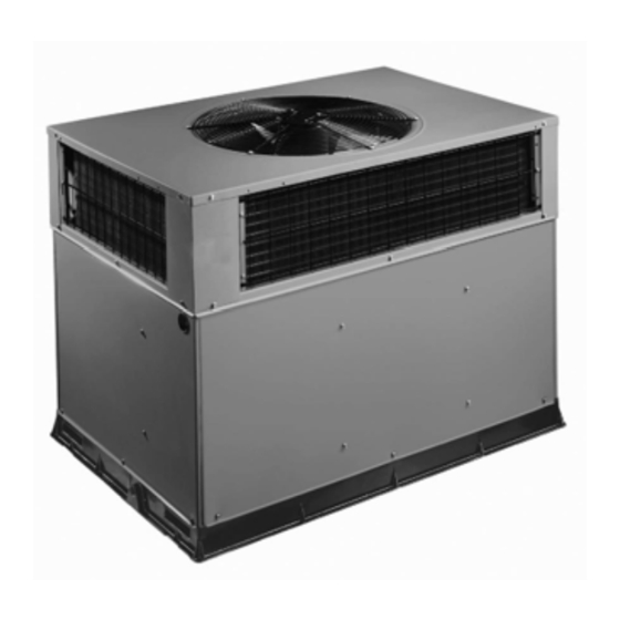
SAFE INSTALLATION REQUIREMENTS We require these instructions as a minimum for a safe installation. WARNING PHN5 HEAT PUMP UNIT FIGURE 1 ELECTRICAL SHOCK HAZARD Failure to follow this warning could result in personal injury or death. Before installing or servicing system, turn off power supply to the unit and install lockout tag. -
Page 3: Roofcurb
-- The unit MUST be situated to provide safe access for equipment, and any other safety precautions that might servicing. apply. -- The existing roof structure MUST be adequate to Training for operators of the lifting equipment should support the weight of the unit or the roof MUST be include, but not be limited to, the following: reinforced. - Page 4 (included). When straps are taut, the clevis should be a minimum of 36 (914mm) inches above the unit top cover. FIGURE 2 Unit Corner Weight (lbs) and Rigging Rigging Weight Cabinet MODEL NUMBER Small PHN524 PHN536 PHN548 Large PHN560...
- Page 5 FIGURE 3 PHN524 DIMENSIONS...
- Page 6 FIGURE 4 PHN536- -60 DIMENSIONS...
-
Page 7: Select And Install Ductwork
Step 5—Select and Install Duct Connections 2. Avoid abrupt duct size increases and reductions. Abrupt change in duct size adversely affects air The design and installation of the duct system must be in performance. accordance with the standards of the NFPA for installation IMPORTANT: Use flexible transitions between ductwork of non--residence type air conditioning and ventilating and unit to prevent transmission of vibration. - Page 8 Roof Curb Dimensiona FIGURE 5 HVAC unit HVAC unit base base Gask eting inner flange* Scre w Gask eting Scre w (NO TE A) (NO TE A) inner flange* *Gask eting *Gask eting outer flange outer flange Wood nailer* Wood nailer* Flashing field Flashing field supplied...
-
Page 9: Converting Horizontal Discharge Units To Downflow (Vertical) Discharge Units
Condensate water can be drained directly onto the roof in Unit Leveling Tolerances FIGURE 6 rooftop installations (where permitted) or onto a gravel apron in ground level installations. Install a field--supplied condensate trap at end of condensate connection to ensure proper drainage. -
Page 10: High--Voltage Connections
HIGH--VOLTAGE CONNECTIONS SPECIAL PROCEDURES FOR 208--V OPERATION WARNING WARNING ELECTRICAL SHOCK HAZARD ELECTRICAL SHOCK HAZARD Failure to follow this warning could result in personal Failure to follow this warning could result in personal injury or death. injury or death. Before making any wiring changes, switch off the main Before making any wiring changes, switch off the main power supply to the unit and install lockout tag. -
Page 11: Sequence Of Operation
(1.) restart in defrost on next call for heat. and R to Y1. The compressor and indoor fan Table 1—Physical Data - - Unit PHN5 UNIT SIZE PHN524 PHN536 PHN548 PHN560 NOMINAL CAPACITY (ton) OPERATING WEIGHT lb (kg) - Page 12 Typical Installation FIGURE 9 PHN5 With Duct Covers On FIGURE 10 Duct Covers Condensate Drain FIGURE 11 1” (25 mm) MIN . TRAP OUTLET 2” (51 mm) MIN .
- Page 13 FIGURE 12 PHN524- -60 (208/230- -1- -60) Wiring Diagram...
-
Page 14: Pre--Start--Up
PRE- -START- -UP Make sure that all tools and miscellaneous loose parts have been removed. WARNING 5. Each unit system has two (2) Schrader--type ports, one low--side Schrader fitting located on the suction line, and one high--side Schrader fitting located on the FIRE, EXPLOSION, ELECTRICAL SHOCK HAZARD compressor discharge line. -
Page 15: Start--Up Adjustments
2. Repair leak following Refrigerant Service procedures. pressure (psig) to determine desired system operating liquid line temperature (See Fig. 18). NOTE: Install a bi--flow filter drier whenever the system has 6. Compare actual liquid line temperature with desired been opened for repair. liquid line temperature. -
Page 16: Continuous Fan Operation
NOTE: If accessory electric heat is installed in the unit, Continuous Fan Operation the dry airflow must meet or exceed the minimum airflow The continuous fan operates at the same fan speed as specified in Table 2 for the specific size. Use Table 4 to low stage cooling fan operation. -
Page 17: Defrost Control
Typical Heat Pump Operation - - Heating Mode FIGURE 15 INDOOR COIL OUTDOOR COIL Bypass Position Metering Position LEGEND HPS – High Pressure Switch LCS – Loss of Charge Switch Accurater Metering Device Metering Device ® Arrow indicates direction of flow Step 3 —... -
Page 18: Air Filter
To clean the blower motor and wheel: CAUTION 1. Remove and disassemble blower assembly as follows: UNIT OPERATION HAZARD Remove unit access panel. Disconnect 5 pin plug and 4 pin plug from indoor Failure to follow this caution may result in improper operation. - Page 19 Table 4—Dry Coil Air Delivery* - - Horizontal and Downflow Discharge - - Unit PHN524- -60 Unit Motor Wire External Static Pressure (IN. W.C.) (Voltage) Speed Color Blue Med-Low Pink PHN524 Medium (208/230--1--60) Med-High Orange 1179 1118 1061 High Black...
-
Page 20: Outdoor Coil, Indoor Coil, & Condensate Drain Pan
water, using a garden hose. Be careful not to splash Step 2 — Outdoor Coil, Indoor Coil, and Condensate water on motors, insulation, wiring, or air filter(s). For best Drain Pan results, spray condenser coil fins from inside to outside Inspect the condenser coil, evaporator coil, and the unit. -
Page 21: Outdoor Fan
FIGURE 17 Defrost Control Speedup Quiet Defrost interval Pins Shift DIP switches Step 3 — Outdoor Fan Keep the condenser fan free from all obstructions to clean all the parts, restrip the wire end and reassemble ensure proper cooling operation. Never place articles on the connection properly and securely. -
Page 22: Metering Devices-- Txv & Piston
problem exists, be sure that all supply--air and return--air Step 10 — High- -Pressure Switches grilles are open and free from obstructions, and that the The high--pressure switches are located on the discharge air filter is clean. When necessary, refer to Indoor Airflow line and protect against excessive condenser coil and Airflow Adjustments section to check the system pressure. -
Page 23: Compressor Oil
Compressor Oil NOTE:Because these switches attached refrigeration system under pressure, it is not advisable to The compressor in this system uses a polyolester (POE) remove this device for troubleshooting unless you are oil, Mobil 3MAF POE. This oil is extremely hygroscopic, reasonably certain that a problem exists. -
Page 24: R--410A Quick Reference Guide
R- -410A QUICK REFERENCE GUIDE R--410A refrigerant operates at 50--70 percent higher pressures than R--22. Be sure that servicing equipment and replacement components are designed to operate with R--410A refrigerant. R--410A refrigerant cylinders are rose colored. Recovery cylinder service pressure rating must be 400 psig, DOT 4BA400 or DOT BW400. R--410A systems should be charged with liquid refrigerant. -
Page 25: Troubleshooting
Table 8—Troubleshooting Chart SYMPTOM CAUSE REMEDY Power failure Call power company Fuse blown or circuit breaker tripped Replace fuse or reset circuit breaker Defective contactor, transformer, or high-- pressure, loss--of--charge or low--pressure Replace component Compressor and condenser fan will switch not start. -
Page 26: Start-Up Checklist
START-UP CHECKLIST (Remove and Store in Job File) I. Preliminary Information MODEL NO.:_________________________________ SERIAL NO.:__________________________________ DATE:_______________________________________ TECHNICIAN:_________________________________ II. PRE-START-UP (Insert checkmark in box as each item is completed) ( ) VERIFY THAT ALL PACKING MATERIALS HAVE BEEN REMOVED FROM UNIT ( ) REMOVE ALL SHIPPING HOLD DOWN BOLTS AND BRACKETS PER INSTALLATION INSTRUCTIONS ( ) CHECK ALL ELECTRICAL CONNECTIONS AND TERMINALS FOR TIGHTNESS ( ) CHECK GAS PIPING FOR LEAKS (WHERE APPLICABLE)
Need help?
Do you have a question about the PHN524 and is the answer not in the manual?
Questions and answers