
Related Manuals for Endress+Hauser Cleanfit P CPA471


Summary of Contents for Endress+Hauser Cleanfit P CPA471
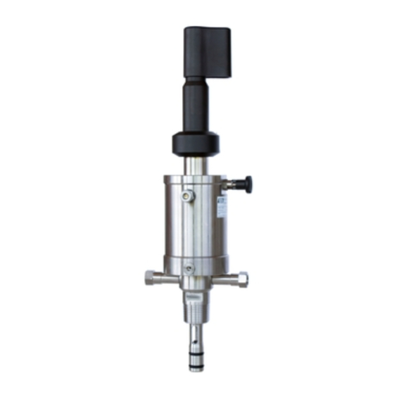
- Page 1 Operating Instructions Cleanfit P CPA471 Retractable process assembly BA00217C/07/EN/13.12 71161810...
-
Page 3: Table Of Contents
Mechanical construction ....34 Index ......35 Endress+Hauser... -
Page 4: Safety Instructions
Cleanfit CPA471 Safety instructions Designated use The manually or pneumatically operated retractable assembly Cleanfit P CPA471 is designed for installing pH/ORP sensors in tanks and pipes. Its mechanical design permits its use in pressurized systems (see "Technical data"). Any other use than the one described here compromises the safety of persons and the entire measuring system and is not permitted. -
Page 5: Notes On Safety Icons And Symbols
Cause (/consequences) injury. Consequences if safety message is not heeded • Corrective action This symbol alerts you to situations that can result in damage to NOTICE property and equipment. Cause/situation Consequences if safety message is not heeded • Action/note Endress+Hauser... -
Page 6: Identification
Afterwards, export the order code as a PDF or Excel file. To do so, click the appropriate button at the top of the page. Scope of delivery The scope of delivery comprises: • Cleanfit assembly (ordered version) • Operating Instructions (English) If you have any questions, please contact your supplier or your local sales center. Endress+Hauser... -
Page 7: Installation
75° 75° 75° 15° 15° 0° 0° 0° 0° a0008528 Fig. 1: Installation angles for glass sensors (X) and ISFET sensors (Y) Inadmissible installation angle Limited permissible angle (air bubbles can build up in the chamber) Recommended installation angle Endress+Hauser... - Page 8 Use a flow assembly to install the assembly in smaller pipe diameters (see Accessories). When designing the installation nozzle, please observe the total immersion depth in operation (sensor holder not inserted). Ensure that the sensor is always immersed in the medium during operation (see "Dimensions"). Siphon effect: line emptied by vacuum Endress+Hauser...
- Page 9 Cleanfit CPA471 Installation 3.2.2 Dimensions 80 (3.15) Ø 24.8 (0.98) Ø 18 (0.71) mm (inch) a0008304 a0008306 Fig. 3: Long version for gel sensors Fig. 4: Short version for KCl sensors Stroke Stroke Endress+Hauser...
- Page 10 Use liquid KCl electrodes with the short version only! 3.2.3 Process connections a0008305 Fig. 6: Process connections (short version) G1¼ internal thread with union nut DN 50 dairy fitting NPT 1" external thread Triclamp 2" Endress+Hauser...
- Page 11 Cleanfit CPA471 Installation mm (inch) a0008303 Fig. 7: Process connections (long version) DN 50 flange G1¼ internal thread with union nut DN 50 dairy fitting NPT 1" external thread Triclamp 2" Endress+Hauser...
-
Page 12: Installation Instructions
Canisters for cleaning and buffer solutions Assembly Cleanfit Superheated steam/water/cleaning solutions Transmitter Mycom CPM153 (optional) Special measuring cable Rinse block Communication / power supply cable Rinse water valve Power supply Mycom Power/signal cables Power supply CPG310 Air hoses Control unit CPG310 Media Endress+Hauser... - Page 13 • Install a pressure-reducing valve upstream of the assembly. • We recommend you also use a pneumatic throttle for lower pressures. This results in smoother assembly operation. Such a throttle is available as an accessory (see "Accessories" section). pneumatically operated assembly only Endress+Hauser...
- Page 14 G 1/8 pneumatics connection (Fig. 11). Also, connect the compressed air supply line no. n to the inlet (1) of the lower limit position switch (M2, via T-piece). This limit position switch supplies the position feedback signal "Assembly measuring". Endress+Hauser...
- Page 15 Water pressure too high The assembly could be damaged. • If it is possible for the water pressure to rise above 6 bar (87 psi, including any transient pressure surges), install a pressure reducing valve upstream. Otherwise the assembly may be damaged. Endress+Hauser...
-
Page 16: Sensor Installation
• If turned in the opposite direction, the stop lock bolt does engage, too. This could, however, loosen the sensor holder. The reason for this are adhesions on the lower part of the sensor holder. These can cause the sensor holder to get stuck, producing a counterforce when unscrewing the sensor holder. Endress+Hauser... - Page 17 Remove the sensor in the reverse sequence of operations. In case of symmetrical pH measurement, you must push the PML connector onto the PML connection (PML = potential matching line, position 1). Please, read the Operating Instructions of the transmitter. Endress+Hauser...
-
Page 18: Post-Installation Check
Remove the sensor in the reverse sequence of operations. Post-installation check • After installation, check that all connections are firmly in position and leak-tight. • Ensure that the hoses cannot be removed without force. • Check all hoses for damage. Endress+Hauser... -
Page 19: Operation
Turn the bolt by 90° so that the plastic grooves rest on the metal edge. Locking the stop lock bolt: Turn the stop lock bolt through 90° so that the plastic grooves are located above the recesses. When the retractable pipe is turned clockwise, the bolt engages. Endress+Hauser... -
Page 20: Manual Operation
Otherwise the assembly can no longer move automatically to the "Measuring" position. If a maintenance switch is fitted on the transmitter, set it to "Maintenance" or "Service". It is not possible to lock the assembly in the "Measuring" position. The pneumatic system maintains the back pressure to the process pressure. Endress+Hauser... -
Page 21: Maintenance
• After cleaning the sensor, rinse the rinse chamber of the assembly with copious amounts of water (possibly distilled or de-ionized). Otherwise, remaining residues of cleaning agent can corrupt measurement. • If required, re-calibrate after cleaning. in reverse sequence of operations to the installation procedure with the corresponding assembly equipment only Endress+Hauser... -
Page 22: Cleaning Agents
Interrupt the process. Beware of medium residues, residual pressure and higher temperatures. Move the assembly to the "Service" position. Secure this position by the stop lock bolt (pos. 7). Dismount the sensor. Dismount the assembly from the process connection. Clean the assembly (see chapter "Cleaning the assembly). Endress+Hauser... - Page 23 Pull the stop bolt and turn it by 90° (unlock). Pull the sensor holder (pos. 5) downwards out of the cylinder. Replacing the seals Apply a thin layer of grease to the new seals (e.g. Syntheso Glep1). Replace the seals as shown in Fig. 22. Re-assemble the assembly. Endress+Hauser...
- Page 24 10+11 51502804 Pos. 20 ID18.00 W4.00 KALREZ 51502802 Pos. 30 ID19.00 W3.00 EPDM 51502803 Pos. 30 ID19.00 W3.00 VITON 51502804 Pos. 30 ID19.00 W3.00 KALREZ 71064624 Pos. 80 ID23.52 W1.78 KCl version 71064624 Pos. 90 ID55.25 W2.62 KCl version Endress+Hauser...
-
Page 25: Accessories
Dummy plug for G¼ rinse connection, • SS 1.4404 (AISI 316L); order no. 50092264 DN 25 flow vessel, • G1¼ external thread, SS 1.4404 (AISI 316L); • order no. 51502801 G1¼ 160 (6.30) mm (inch) a0007567 Fig. 24: Flow vessel Endress+Hauser... -
Page 26: Limit Position Switches
• Ordering per product structure (--> Online configurator, www.products.endress.com/cps71 or www.products.endress.com/cps71d) • Technical Information TI245C/07/EN Ceragel CPS72/CPS72D • ORP electrode • With double chamber reference system and integrated bridge electrolyte • Ordering per product structure (--> Online configurator, www.products.endress.com/cps72 or www.products.endress.com/cps72d) • Technical Information TI374C/07/EN Endress+Hauser... - Page 27 • Ordering per product structure (--> Online configurator, www.products.endress.com/cps441 or www.products.endress.com/cps441d) • Technical Information TI352C/07/EN Tophit CPS491/CPS491D • ISFET sensor with open aperture for media with high dirt load; • Ordering per product structure (--> Online configurator, www.products.endress.com/cps491 or www.products.endress.com/cps491d) • Technical Information TI377C/07/EN Endress+Hauser...
-
Page 28: Trouble-Shooting
The assembly must once again meet the technical data specifications when it has been repaired. Replace all other damaged components immediately. To order accessories and spare parts, please use the "Accessories" and "Spare parts" chapters or contact your local sales center. Endress+Hauser... -
Page 29: Spare Part Kits
Cleanfit CPA471 Trouble-shooting Spare part kits a0008561 Fig. 25: Spare parts (all assembly versions) item numbers in → å 25. Refer to the table on the next page for the order numbers of the spare part kits based on the Endress+Hauser... - Page 30 71064624 Sensor guide, standard version, complete 51503719 For assembly version: – short, immersion depth up to 101 mm (3.98 inch) Sensor guide, standard version, complete 51503720 For assembly version: – long, immersion depth up to 208 mm (8.19 inch) Endress+Hauser...
- Page 31 – long, immersion depth up to 208 mm (8.19 inch) 18-20 SS 1.4404 (AISI 316L) cylinder (pos. 20), with O-ring (pos. 6-1), cylinder head 51503776 (pos. 19), screws (Pos. 18) For assembly version: – long, immersion depth up to 208 mm (8.19 inch) Endress+Hauser...
-
Page 32: Return
The device must be returned if repairs or a factory calibration are required, or if the wrong device has been ordered or delivered. According to legal regulations, Endress+Hauser, as an ISO-certified company, is required to follow certain procedures when handling returned products that are in contact with medium. -
Page 33: Technical Data
Pressure temperature diagram p [psi] [bar] 43.5 T [°C] T [°F] a0008139 Fig. 26: Pressure-temperature diagramm PA housing (manual actuation only) Stainless steel housing 1.4404 (AISI 316L) The process pressure for a manually driven assembly must not exceed 4 bar (58psi)! Endress+Hauser... -
Page 34: Mechanical Construction
Rinse fittings SS 1.4404 (AISI 316L) Material Cylinder PA / SS 1.4404 (AISI 316L) (not in contact with Electric limit position switch fore-part PBT, cable PVC medium) Rinse connection fittings 2 x G¼ (internal) or 2 x NPT ¼" (internal) Endress+Hauser... -
Page 35: Index
Measuring system ....... 12 Mechanical construction ......34 Endress+Hauser... - Page 36 BA00217C/07/EN/13.12 Printed in Germany / FM+SGML 6.0 / DT 71161810...
Need help?
Do you have a question about the Cleanfit P CPA471 and is the answer not in the manual?
Questions and answers