Table of Contents
Advertisement
Quick Links
Advertisement
Chapters
Table of Contents

Related Manuals for Blastrac BMP-335


Summary of Contents for Blastrac BMP-335
- Page 1 Operating Manual BMP-335...
- Page 2 Blastrac B.V. Utrechthaven 12 3433 PN Nieuwegein THE NETHERLANDS T +31(0)30 - 601 88 66 F +31(0)30 - 601 83 33 E info@blastrac.nl I www.blastrac.com Technical data Safety instructions Nieuwegein General Transport Initial operation Operation Maintenance Electrical systems Fault diagnosis...
- Page 4 BMP-335EHY Operation Manual Technical Data Contents Chapter 1 1.1 Rating 1.2 Unit specifications 1.3 Operative range and correct usage 1.4 Stand-by power supply 1.5 Machine type designation 1.6 Advice’s for operators of the scarifier...
-
Page 5: Unit Specifications
Drive motors, progressively adjustable forward and reverse Scarifying output up to 150 m²/h Dust hose connection 75 mm Ø Recommended Filter unit Contact Blastrac for a suitable filter unit Noise Level Lp A 97,3 dB Vibration Level 4,17 ms²... -
Page 6: Operative Range And Correct Usage
BMP-335EHY Operation Manual Technical Data Dimensions: BMP-335EHY Length 1400 Width Height 1075 Weight (incl. drum) 1.3 Operative range and correct usage The scarifier BMP-335EHY is exclusively designed to clean horizontal surfaces. The machine may not be used for other purposes. The manufacturer will not be liable for damage resulting from such incorrect usage. -
Page 7: Machine Type Designation
Manual BMP-335EHY Technical Data 1.5 Machine type designation BMP - 335 EHY Product type Working width Mode of driving 1.6 Advice for operators of the scarifier When you use the scarifier BMP-335EHY it is possible to exceed the allowed scale of sound level of 85 db(A). If the scale of sound level reaches 85 db(A) or more, the operators and the persons who work in the surroundings must wear noise protection. -
Page 8: Table Of Contents
BMP-335EHY Operation Manual Safety Advices Contents Chapter 2 2.0 Warnings and symbols 2.1 Organisational measures 2.2 Personnel selection and qualification 2.3 Safety precautions applicable to some operating sequences 2.4 Special work within the scope of use of the equipment and maintenance activities as well as repairs during operation 2.5 Definition of the Safety off position 2.6 Particular dangerous aspects of the equipment... -
Page 9: Warnings And Symbols
BMP-335EHY Safety Advices 2.0 Warnings and Symbols The following denominations and symbols are used in the Operating Instructions to highlight areas of particular importance: Symbol of operational safety. In these Operating Instructions this symbol will be shown next to all safety precautions that are to be taken in order to ensure prevention to life and injury. - Page 10 BMP-335EHY Operation Manual Safety Advices Warning against dangerous voltages. Indications relating to protective devices in electrical appliances. Indications relating to protective devices in electrical appliances. Instructions relating to periodical checks. Reference to important instructions contained in the Operating Instructions.
-
Page 11: Organisational Measures
BMP-335EHY Safety Advices 2.1 Organisational measures The Operating Instructions are to be kept near the location where the machine is located and must be within reach at all times! In addition to the Operating Instructions general and legal regulations regarding accident prevention and environmental protection must be complied with and indicated! Such duties may for example relate to the handling of hazardous substances or to the provision and wearing of personal protection... -
Page 12: Personnel Selection And Qualification
BMP-335EHY Operation Manual Safety Advices If safety-critical changes occur to the machine or its working method, the machine must be shut down immediately! The cause of the fault must be established immediately! Changes, add-ons or conversions to the machine which might impair safety must not be undertaken without the manufacturer’s permission! This applies in particular to the fitting and adjustment of safety... - Page 13 BMP-335EHY Safety Advices Define responsibilities of the machine operator also regarding to traffic safety regulations and empower him to decline instructions from third parties which are not complying with the safety requirements! Personnel being trained or made acquainted with the equipment may only be deployed on the machine under constant supervision of an experienced person! Work on electrical equipment or operating materials may only be...
-
Page 14: Special Work Within The Scope Of Use Of The Equipment And
BMP-335EHY Operation Manual Safety Advices Faults must be immediately rectified! Carry out the switch on and off operations and pay attention to control display according to the operation manual! Before switching on the machine make sure that no-one can be endangered when the machine starts up! Do not switch off or remove the exhaust and ventilation devices when the machine is running! - Page 15 BMP-335EHY Safety Advices The operator has to be informed about all kind of maintenance works before starting the process! At all works that are related to normal operation, conversion of tools adjustment of the machine and its safety devices as well as before inspection , maintenance and repair all ON and OFF functions have to be carried out according the operation manual and advises for maintenance and repair.
-
Page 16: Definition Of The Safety Off Position
BMP-335EHY Operation Manual Safety Advices 2.5 Definition of the Safety off position Definition: The machine is in a safe condition when it cannot generate any hazard. Putting the equipment in the Safety off position means: Manipulate the quick lift (Upper Position). Switch off the machine. -
Page 17: Electrical Engineering Regulations
BMP-335EHY Safety Advices 2.7 Electrical engineering regulations Work on electrical equipment or operating materials may only be undertaken by a skilled electrician or by trained persons under the guidance and supervision of a skilled electrician as well as in accordance with the electrical engineering regulations. Use only extension cable for extending the main cable that are sized and marked in accordance with the overall power consumption of the machine and the valid VDE guidelines.. - Page 18 BMP-335EHY Operation Manual General Contents Chapter 3 Care and maintenance Scope of supply Description Control box Operating elements The scarifying drum The scarifying flailes...
-
Page 19: Care And Maintenance
Operation Manual BMP-335EHY General 3.1 Care and maintenance Special attendance and regular maintenance of the machine are imperative for functioning and safety. 3.2 Scope of supply Scope of supply of the machine: Scarifier (BMP-335EHY) Filter unit Dust hose (Option) Operating manual 2 x... -
Page 20: Description
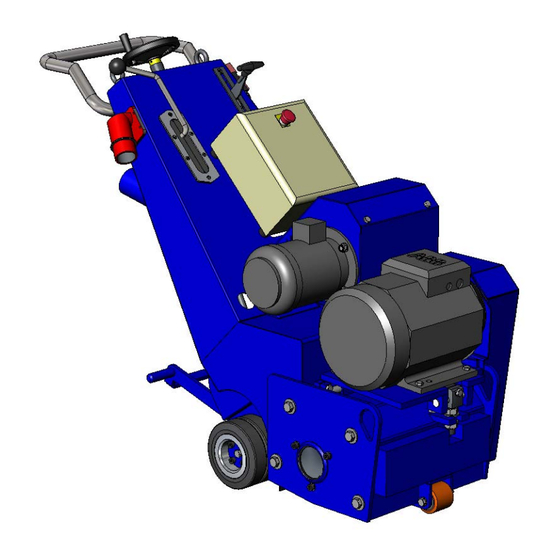
Handwheel working depth Hydraulic pump housing The Blastrac scarifier of the range of BMP-335EHY will be supplied, dependent on your request, with an electrical motor 400 V or with a internal combustion engine at a working width of 335 mm. Both are comfortable machines thanks to their hydraulic drive unit. -
Page 21: Control Box
• To make non-slip surfaces A specially designed dust collection system ensures nearly dust-free operation of the machine and clean air at the workspace. Blastrac uses specially designed dust collection systems which guarantee a high cleaning level. 3.4 Control box Fig. - Page 22 BMP-335EHY Operation Manual General "Scarify motor ON/OFF" Switch Pressing the " Scarify motor ON" push button, switches the scarify motor. Before switching on the scarify motor, the treadle (see pos. 1 figure 3.1) of the drive system must be in downwards position. Emergency touch switch The emergency shutdown is a red mushroom-shaped press switch.
-
Page 23: Operating Elements
3.5 Operating elements The Quick lift The Blastrac scarifier BMP-335EHY has a quick lift (Fig. 3.1 Item 4). The scarifier can be lift with the quick lift lever without changing the working depth to transport or to remove it. Before switching on the machine, the scarifier must be lifted with quick lift in order to prevent a start or rather a run out of the motor under full load. -
Page 24: The Scarifying Drum
BMP-335EHY Operation Manual General 3.6 The scarifying drum The heart of the scarifier is the scarifying drum. The assembly of the scarifying drum is very easy. Each tool will be pushed on the axle together with spacers according to the enclosed assembly plans. -
Page 25: The Scarifying Flailes
3.7 The scarifying flailes Through a lot of different flailes, and with few alterations, it is possible to adjust the Blastrac - Scarifier for the applications or rather for the requirements of the specific surfaces. All the machines work according the principle of the loose of a tool seated on an axle. - Page 26 BMP-335EHY Operation Manual Transport Contents Chapter 4 4.1 Transport of the machine with vehicle 4.2 Manual mode of moving the machine 4.3 Transport with cranes or lifts 4.4 Operation of the machine while scarifying 4.5 Unit specifications...
- Page 27 Operation Manual BMP-335EHY Transport 4.1 Transport of the machine with vehicles When transporting the machine proceed in such a manner that damage due to the effects of the use of force or incorrect loading and unloading is avoided. Secure the machine with a tightening belt. Use at least two belts and tighten the machine..
- Page 28 BMP-335EHY Operation Manual Transport 4.5 Unit specifications Model variant BMP-335EHY Dimensions in mm 1400 x 605 x 1075 L x W x H Weight 405 kg...
- Page 29 BMP-335EHY Operation Manual Initial operation Contents Chapter 5 5.1 Preparations for initial operations 5.2 Initial operations...
-
Page 30: Initial Operation
Operation Manual BMP-335EHY Initial operation 5.1 Preparation for initial operations Before switching on make sure that all existing protective devices are mounted and that the filter unit is connected correctly. Handle all plugs, cables, hoses and operating devices with care. Avoid any contact with live wires. - Page 31 BMP-335EHY Operation Manual Initial operation Before start-up the operating personnel must be familiar with the safety regulations given in this manual. Put the scarifier and the filter unit on the surface to be treated. In order to move the machine manually, manipulate the quick lift as described in chapter 3.5.
- Page 32 Operation Manual BMP-335EHY Initial operation 5.2 Initial operations All persons in the proximity of the machine, while it is working, must wear ear protectors, safety glasses with lateral protection as well as safety shoes. The operator is obliged to wear tight protective clothing.
- Page 33 BMP-335EHY Operation Manual Initial operation When you start the machine check the turning directions of the drive motor. (See turning directions arrow on the motor housing). The scarifier goes forward for a short-erm in case of wrong turning direction of the driving device. It is possible that it drives on suddenly in the opposite direction without adjusting the drive unit control lever.
- Page 34 Operation Manual BMP-335EHY Initial operation Now , after this adjustment you can adjust the travel speed with the drive unit control lever. The machine can run forward and also reverse. The advancing speed is dependent on the conditions and the required surface profile of the surface to be treated.
- Page 35 BMP-335EHY Operation Manual Operation Contents chapter 6 6.1 Operation 6.2 Rate of Feed Information 6.3 Recommended direction of operation 6.4 Switching-off the machine 6.5 Trouble Shooting 6.6 Safety shutdown 6.7 Restarting after a fault 6.8 Proceedings- prior and after stationary period...
- Page 36 Operation Manual BMP-335EHY Operation 6.1 Operation Normal start-up and operation of the scarifier BMP-335EHY isn’t different from the procedure described in Chapter 5 “Initial operation”. Carry out scarifying operation in parallel tracks in such a way that the dust hose and electric cable do not become twisted. Figure 6.1 shows the recommended scarifying paths leading away from the filter unit.
- Page 37 BMP-335EHY Operation Manual Operation 6.3 Recommended scarifying direction Position the filter unit near to a power supply connection. Place the scarifier near to the filter unit and spread out the hose as shown in fig. 6.1. Work with the scarifier, with the hose spread out in the opposite direction, repeating the process away from the filter unit.
- Page 38 Lift the scarifying drum from the surface by the quick lift. Push the red button Switch of the connected filter unit. When the Blastrac scarifier is put out of operation for a longer period of time, pull out the mains plug and cover the machine with a plastic foil.
- Page 39 BMP-335EHY Operation Manual Operation 6.6 Safety shutdown The machine has to be into its “Safety off position” before starting repair works. See Chapter 2.5 “Safety instructions”. 6.7 Restarting after a fault See Chapter 5 “Initial operation“. 6.8 Proceedings- prior and after stationary period Before a long standstill period Switch off the machine (see Chapter 6.4).
- Page 40 BMP-335EHY Operation Manual Maintenance Contents Chapter 7 7.1 Recommendations 7.2 Maintenance and inspection list 7.3 Repairing 7.4 The scarifying drum 7.5 Drum Assembly Layout 7.6 Drum Replacement 7.7 Influences on the pattern of the scarifier 7.8 Belt drive 7.9 The Motor 7.10 Lubrication 7.11 Traction drive...
- Page 41 Operation Manual BMP-335EHY Maintenance 7.1 Recommendations Prior to any repair works on the machine and its drives, secure the machine against unintentional switching-on. Put the machine to its safety off position. Chapter 2.5 Failures due to inadequate or incorrect maintenance may generate very high repair costs and long standstill periods of the machine.
- Page 42 As already mentioned in Chapter 5 “Initial operation” we recommend to execute the first repair works on the machine having support of Blastrac personnel. Doing this together , your maintenance personnel gets the opportunity to be trained intensely. We will describe only regular maintenance works that could occur within the bounds of regular maintenance or work that is required to replace wear parts.
- Page 43 If the scarifying drum is not uniform assembled the machine will become unbalanced and excessive wear, will arise. Blastrac will not feel responsible for any faulty parts, that are damaged caused by inappropriate assembly.
- Page 44 BMP-335EHY Operation Manual Maintenance Following important key factors affect the scarifying pattern: • The selected speed must be suitable for the conditions of the surface. • You need to choose appropriate tools for different application. 7.5 Drum Assembly Layout We have tested the assembly layout examples enclosed in this manual they will result in the best possible pattern being achievable.
- Page 45 Operation Manual BMP-335EHY Maintenance 7.6 Drum Replacement Prior to any repair works on the machine and its drives, secure the machine against unintentional switching-on. Put the machine to its safety off position. Chapter 2.5 Disassembly: Loosen the fastening screws on the side plate fitted to the housing and remove them.
- Page 46 BMP-335EHY Operation Manual Maintenance Assembly: 1 Clean the main shaft and lubricate it uniform 2 Push the scarifying drum on the drive shaft until it hits its heel. 3 Fit back the side plate and pay attention to have the correct position to avoid damaging the bearing that’s located in the side plate.
- Page 47 Operation Manual BMP-335EHY Maintenance 7.7 Influence on the pattern of the scarifier The scarifying pattern depends on the surface being treated the change of working depth, tool selection and selected speed will mostly have influence on the result. Depending on the required surface structure you will have to change the tools (Flails) .
- Page 48 BMP-335EHY Operation Manual Maintenance 7.8 Belt drive Prior to any repair works on the machine and its drives, secure the machine against unintentional switching-on. Put the machine to its safety off position. Chapter 2.5 Fig. 7.2 Motor Counter nut Adjusting nut Belt Belt tension The correct belt tension is of utmost importance in order to obtain a...
- Page 49 Operation Manual BMP-335EHY Maintenance Belts dismount and Belts mounting Prior to any repair works on the machine and its drives, secure the machine against unintentional switching-on. Put the machine to its safety off position. Chapter 2.5 Dismantling: 1. Remove the protection cover for synchronous belt 2.
- Page 50 The motor is designed for a long working life Damages at the motor can be perceived through unusual noises , malfunctions or rather interruptions. If the malfunction can not be repaired, inform please the Blastrac service centre. 7.10 Lubrication The observance of our lubrication instructions will preserve you from premature maintenance and repair works on your machine.
- Page 51 Operation Manual BMP-335EHY Maintenance Lubrication service The machine will be provided with the necessary quantity of grease. applied during assembly. Independent from the initial grease fillings check regular linkages and points mentioned as follows: Before the first start up, please take into account following points: Control the oil-level in the hydraulic oil reservoir (picture 7.4) Check the handwheel working depth adjustment for soft...
- Page 52 BMP-335EHY Operation Manual Maintenance Lubrication Points 1. Lubricator nipples under the handwheel working depth adjustment. Fig. 7.5...
- Page 53 Operation Manual BMP-335EHY Maintenance 7.11 Traction Drive Disassemble the drive wheel (2), by loosen the bolt (1). Remove chain guard (4) by loosen the bolt (3). Apply oil only in this section and clean up all parts in order to remove excessive oil.
- Page 54 BMP-335EHY Operation Manual Electrical system Contents Chapter 8 8.1 Electric circuits diagrams 8.2 Hydraulic circuits diagrams...
-
Page 55: Electrical System
Order the electric items with reference to the circuit diagrams in chapter 8.1 or call a Blastrac service centre. - Page 56 BMP-335EHY Operation Manual Electrical system Electric circuits diagram...
- Page 57 0 1 2 3 4 5 6 7 8 9 Particulars: PROJECT Client Blastrac B.V. Name BMP NY 335 Supplier Blastrac B.V. SUPPLIER Contact Telephone +31(0)306018866 Draw.number PJ06.03112T2B Telefax +31(0)306018333 Order number Email DATA Arch.number PJ06.03112T2B Calc. number Status As Built Start of project 13.Mrt.2007 Highest page number Latest change 12.Apr.2007 ( GKU) Number of pages...
- Page 58 9 Table of contents Latest change Page Summary Engineer Front page 13.Mrt.2007 Table of contents 12.Apr.2007 Explanations 13.Mrt.2007 Symbol explanation 13.Mrt.2007 Mainvoltage 12.Apr.2007 Controlvoltage 12.Apr.2007 Terminal strip X1 12.Apr.2007 Revision Start 13.Mrt.2007 Arch.nr. Blastrac B.V. Table of contents PJ06.03112T2B Revision Eng. BMP NY 335 Draw.nr. Pages Page Revision Print 12.Apr.2007 PJ06.03112T2B Revision Status As Built...
- Page 59 Black Black PE / ¤ Yellow / Green Consecutive numbering Symbol letter Controlvoltage alternatingvoltage (AC) Page number Group (in case used) Phase Red Hookup wire Red Zero Red Archive number explanation: PJ01.01234T1A Revision letter Serial number Archive number Revision Start 13.Mrt.2007 Arch.nr. Blastrac B.V. Explanations PJ06.03112T2B Revision Eng. BMP NY 335 Draw.nr. Pages Page Revision Print 12.Apr.2007 PJ06.03112T2B Revision Status As Built...
- Page 60 Ammeter Fuses Dropout delayed Emergency stop NC Voltmeter Fuse terminal Contact NO / NC Working hour counter Earthleakage switch Thermal Earthleakage protection Key switch Current coil Installation automatic Shortcircuit and NO / NC overcurrent protection Thermostat NO / NC Motor Autotransformer Revision Start 13.Mrt.2007 Arch.nr. Blastrac B.V. Symbol explanation PJ06.03112T2B Revision Eng. BMP NY 335 Draw.nr. Pages Page Revision Print 12.Apr.2007 PJ06.03112T2B Revision Status As Built...
- Page 61 GV2ME21 420V 6KM2 6KD2 6KS2 6KM1 RM4TG20 75VA ¤ ¤ ¤ ¤ supply Motor Hydro drive Phase 420V 50Hz. 11 kW / 21 A 1,5 kW 3,4 A sequence Revision Start 13.Mrt.2007 Arch.nr. Blastrac B.V. Mainvoltage PJ06.03112T2B Revision Eng. BMP NY 335 Draw.nr. Pages Page Revision Print 12.Apr.2007 PJ06.03112T2B Revision Status As Built...
- Page 62 2 5.6 2 5.2 2 5.5 2 5.4 4 5.6 4 5.3 4 5.5 4 5.4 6 5.6 6 5.3 6 5.5 6 5.4 14 6.3 14 6.4 22 6.5 22 6.4 56 6.4 68 6.5 Revision Start 13.Mrt.2007 Arch.nr. Blastrac B.V. Controlvoltage PJ06.03112T2B Revision Eng. BMP NY 335 Draw.nr. Pages Page Revision Print 12.Apr.2007 PJ06.03112T2B Revision Status As Built...
- Page 63 0 1 2 3 4 5 6 7 8 9 Internal connection Bridges Terminal Revision Start 13.Mrt.2007 Arch.nr. Blastrac B.V. Terminal strip X1 PJ06.03112T2B Revision Eng. BMP NY 335 Draw.nr. Pages Page Revision Print 12.Apr.2007 PJ06.03112T2B Revision Status As Built...
- Page 64 Operation Manual BMP-335EHY Electrical system Hydraulic circuits diagrams...
- Page 66 BMP-335EHY Operation Manual Fault diagnosis Contents Chapter 9 9.1 Fault diagnosis - scarifier 9.2 Fault diagnosis - electrical system...
- Page 67 Operation Manual BMP-335EHY Fault diagnosis 9.1 Fault diagnosis - scarifier Prior to any repair works on the machine or its drives the machine must be secured against unintentional switching-on. Put the machine to its Safety off position. Fault Possible cause Remedy Excessive Imbalance due to worn or...
- Page 68 BMP-335EHY Operation Manual Fault diagnosis 9.2 Fault diagnosis - electrical system Prior to any repair works on the machine or its drives the machine must be secured against unintentional switching-on. Put the machine to its Safety off position.. Fault Possible cause Remedy Control system Motor protection switch has...
- Page 69 BMP-335EHY Operation Manual Spare Parts Contents Chapter 10 10.1 Spare parts 10.2 Assembly plans...
- Page 70 Operation Manual BMP-335EHY Spare Parts Drive unit...
- Page 71 BMP-335EHY Operation Manual Spare Parts ITEM QTY. PART NUMBER Description E03854 Drive bracket E03863 Bearing house outer E01477 Bearing E03855 Clutch house E03862 Bearing house inner E03864 Wheel shaft E03860 Shaft slide plate E03861 Slide plate E03936 Bottom sprocket E03939 V-ring seal E03935 Wheel complete...
- Page 72 Operation Manual BMP-335EHY Spare Parts M10-Washer Ø30 M10-Plastic Insert M8x110 Hexagon Socket Head Cap BE0003 M8 WASHER M8 plastic insert nut M10x25 Hexagon Socket Head Cap M12x35 Bolt E03941 Ball Ø20 E03940 Circlip Ø45 M6x30 Hexagon Socket Head Cap...
- Page 73 BMP-335EHY Operation Manual Spare Parts Hydraulic pump & drive control...
- Page 74 Operation Manual BMP-335EHY Spare Parts ITEM QTY. PART NUMBER Description E04001 Pump motor E04050 Coupling part 1 E04052 Coupling insert E04051 Coupling part 2 E03378 E03996_8 1/8 x ½ Woodruff key E03996_1 Hydraulic gearbox E04008 Adapter Nut 3/8-16 UNC E03379 Lever E04004 Cover...
- Page 75 BMP-335EHY Operation Manual Spare Parts Lifting device...
- Page 76 Operation Manual BMP-335EHY Spare Parts ITEM QTY. PART NUMBER Description E03349 Spindle sleeve E03353 Handwheel E03352 Shim 40x28x0.5 E03350 Upper bearing E03326 Bush E03351 Lower bearing E03356 Knee lever E03363 Bushing E03358 Knee lever axle E03362 Bushing E03359 Bearing E03360 Clamping piece E03355 Spindle...
- Page 77 BMP-335EHY Operation Manual Spare Parts Drive ITEM QTY. PART NUMBER Description E03392 Eye bolt E03393 Bolt E03977 Motor base plate E04058 Motor 11 kW E04014 Distance bush Parallel key 10x8x50 E03404 Pulley E04013 Fixation bush E03978 Shaft motor base plate E04009 Belt E03406...
- Page 78 Operation Manual BMP-335EHY Spare Parts Bearing unit complete E03952 ITEM QTY. PART NUMBER Description E04041 Hexagon drive shaft E03313 Bearing house left E04042 Distance ring Circlip Ø80 E03312 Protection ring E03991 Bearing E03316 Distance bush Parallel key 10x8x50 E03952 Bearing unit complete...
- Page 79 BMP-335EHY Operation Manual Spare Parts Side plate & bearing unit ITEM QTY. PART NUMBER Description E03932 Side plate only E03309 Hexagon driving support E03992 Bearing E03310 Protection ring E03307 Cover disk E03308 Distance ring E03305 Bearing housing right Circlip Ø90 Circlip Ø50 M10x25 Hexagon Socket Head Cap M10-Washer...
- Page 80 Operation Manual BMP-335EHY Spare Parts General ITEM QTY. PART NUMBER Description E03974 Main body DG17 Socket box BG11758 Cord for deadman switch E03997 Electrical panel E03989 Rubber gasket E03321 Clamping bar E03317 Front wheel E03931 Frame E03412 Weight 1 E03413 Weight 2 E03382 Handle...
- Page 81 BMP-335EHY Operation Manual Spare Parts 10.2 Assembly plans Only assemble tools and spacers so you while the tools could freely move (Axial-Play min 1-2mm). Every shaft needs to have the same quantity of tools and spacers being fitted in order to prevent unbalances. The following assembly layouts show the minimum components.
- Page 82 Operation Manual BMP-335EHY Spare Parts 10.2 Assembly plans Assembly plan MPD335-5L 24S 1x MPD335-5/1 83x MPL 24 244x MPL 30...
- Page 83 BMP-335EHY Operation Manual Spare Parts Assembly plan MPD335-620L60S 1x MPD335-6/1 48x MPL 60-1 252x MPL 63...
Need help?
Do you have a question about the BMP-335 and is the answer not in the manual?
Questions and answers