Table of Contents
Advertisement
Quick Links
Advertisement
Table of Contents

Subscribe to Our Youtube Channel
Related Manuals for TESVOLT TS 25


Summary of Contents for TESVOLT TS 25
- Page 1 Installation Manual TS 48 V...
-
Page 3: Installation Manual
Installation Manual TESVOLT TS 48 V incl. connection of the TS Series to SMA products TS 25 TS 40 TS 50 E.IA. .ENG- A.11 www.tesvolt.com... -
Page 4: Table Of Contents
Properly installing the addressing switch of the Active Power Unit (APU) 11.3 Power expansion by SMA battery inverter TESVOLT Battery Monitoring (BatMon) Software 12.1 Views and features of TESVOLT Battery Monitoring (BatMon) software 13.2 Menu structure of Battery Monitoring (BatMon) Battery system error and warning messages Maintenance and storage... -
Page 5: About This Document
WARNING! This document applies to TESVOLT storage systems. It provides qualified individuals with support during the installation process. It does not replace the complete instructions provided by the manufacturer SMA, which must still be observed. -
Page 6: Safety
Lithium-Ion batteries • Knowledge of, and adherence to this document and the associated product documentation, including all safety instructions • Participation in TESVOLT certification trainings TS 48 Volt 2.2 Safety information WARNING! Lethal electric shock from damaged components or pole short-circuits: Bridging the battery poles causes a short-circuit resulting in a large flow of electrical current. -
Page 7: Needed Tools
For crimping the lugs of the DC cable Ferrule crimper For crimping the wire end ferrules Voltage measuring device For measuring the grid and battery voltage Battery+ (operating voltage up to 60 V (DC) for TS 48 V) Sunny Island E.IA. .ENG- A.11 www.tesvolt.com... -
Page 8: Transport At End-Customer Site
In areas prone to flooding, the battery cabinet must always be installed in an elevated location where it cannot be reached by flooding. The storage system should be installed in a fire-proof room that is free of fire loads and is sealed with a class F30 fire door. E.IA. .ENG- A.11 www.tesvolt.com... -
Page 9: Technical Datasheet
6 Technical Datasheet OFF-GRID or ON-GRID 47.6 to 58.1V IEC 61000-6-1/2/3/4 10-year capacity guarantee, 5-year system guarantee TESVOLT offers free return of batteries from Germany 3 watt (complete system TS) E.IA. .ENG- A.11 www.tesvolt.com... -
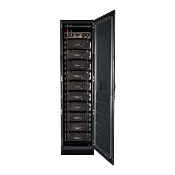
Page 10: Battery Storage Ts
The scope of delivery should be checked against the delivery note and the requirements under point 4 “Transport at end-customer site” and point 5 “Installation location” must be observed. Installation Manual (z.B. TS 40 Rack) E.IA. .ENG- A.11 www.tesvolt.com... -
Page 11: Scope Of Delivery
Installation Manual 48 V Cable connection set (included 2x Copper bars, 1x Patch cabel, 2x Rack Balancing Plug) TS 25, TS 40 or TS 50 Rack Ground cable including fixing material for connection on the provided grounding studs Optional: Cable connection set for connecting the battery to the Sunny Island E.IA. -
Page 12: Connections Active Power Unit (Apu) To Sma Sunny Island
Rotary switch for adjusting the battery’s master/slave connections. Address Further information can be found under point 11.2 Communication link to the battery module. Connect the BAT COM of the APU BAT COM to the BAT COM IN of the first battery module. E.IA. .ENG- A.11 www.tesvolt.com... -
Page 13: Installation Steps
7.4 Installation steps WARNING! Installation and servicing may only be performed by qualified personnel. Only authorised TESVOLT personnel are permitted to open the APU-Unit. Improper use or incorrect configuration may damage the APU-Unit. Opening the APU voids the warranty. Step... - Page 14 Connect the DC copper rails, always bearing in mind that in the 48 V variation, the positive pole must touch the positive pole and the negative pole must touch the negative pole. Tighten the 13 mm screws using 12 nm of torque. >> E.IA. .ENG- A.11 www.tesvolt.com...
- Page 15 Balancing Out. Connect the DC cable from the Sunny Island to the APU (CHARGER). If you do not use pre-assembled cables from TESVOLT, it is important that an earth leakage and short-circuit protected cable (such as NSGAFöU) are used. Connect the communication cable from the Sunny Island (ComSyncIn)
-
Page 16: E-Stop-Contact
In order to implement an external emergency off switch, this bridge must be removed and the emergency off switch connected. Unless this contact is closed, the battery will remain inactive. TERM CAN IN CAN OUT CAN SMA BAT COM Circuit diagram E-Stop Delivery status with E-Stop E.IA. .ENG- A.11 www.tesvolt.com... -
Page 17: Sunny Island Connection
Compatible battery inverters charge automatically based on the parameters stored for the battery and charging infrastructure. Helpful installation and planning information can be found on the homepage of the manufacturer SMA. Anschluss Sunny Island E.IA. .ENG- A.11 www.tesvolt.com... - Page 18 The communication bus must be connected to the battery Lithium-Ion battery and the termination resistor must be plugged into the ComSync Out connection. SMA, SUNNY ISLAND and SUNNYPORTAL are registered trademarks of SMA Solar Technology AG in many countries. E.IA. .ENG- A.11 www.tesvolt.com...
-
Page 19: Commissioning
OK. Now the battery is ready for use. For systems with one Sunny Island, press the power button. For systems with three Sunny Islands, press and hold the power button on the master until you hear a signal tone. E.IA. .ENG- A.11 www.tesvolt.com... - Page 20 846 Ah 10 Battery Modules 940 Ah 11 Battery Modules 1034 Ah 12 Battery Modules 1128 Ah 13 Battery Modules 1222 Ah 14 Battery Modules 1316 Ah 15 Battery Modules 1410 Ah 16 Battery Modules 1504 Ah E.IA. .ENG- A.11 www.tesvolt.com...
-
Page 21: Decommissioning
LED must go out). WARNING! Risk of electric shock, due to the auto-scheduled discharge of the energy storage system. Please wait 15 minutes after switching off the storage system. E.IA. .ENG- A.11 www.tesvolt.com... -
Page 22: Storage System Expansion
11 Storage system expansion The capacity and the charging and discharging power of TESVOLT battery systems can be expanded. 11.1 Capacity expansion using the TESVOLT battery storage system New battery modules are delivered with a state of charge (SoC) of 20%. In order to integrate a new battery module into an existing battery system, the existing system must also be brought to a state of charge of 20%. - Page 23 Capacity expansion 1 Master 2 Slaves IMPORTANT! Up to 4 battery cabinets per cluster can be interconnected in the master / slave mode in parallel. E.IA. .ENG- A.11 www.tesvolt.com...
-
Page 24: Properly Installing The Addressing Switch Of The Active Power Unit (Apu)
Master Slave 1 (from Master 3) Cluster 3 IP-ADRESSE: XXX.XXX.XXX.102 Slave 2 (from M3) Slave 3 (from M3) Master Slave 1 (from Master 4) Cluster 4 IP-ADRESSE: XXX.XXX.XXX.103 Slave 2 (from M4) Slave 3 (from M4) E.IA. .ENG- A.11 www.tesvolt.com... -
Page 25: Power Expansion By Sma Battery Inverter
Islands and the battery. This ensures that electricity is distributed to the Sunny Islands via fuse elements. In a cluster comprising three Sunny Islands, one Sunny Island will serve as the Master, which will control the other two Sunny Islands as Slave 1 and Slave 2. E.IA. .ENG- A.11 www.tesvolt.com... - Page 26 Cluster 1: 3 x Sunny Island 6.0H (13.8 kW) with TS 40 Battery (up to 38.4 kWh) Cluster 2: 3 x Sunny Island 8.0H (18.0 kW) with 4 x TS 40 Battery (up to 153.6 kWh) E.IA. .ENG- A.11 www.tesvolt.com...
-
Page 27: Tesvolt Battery Monitoring (Batmon) Software
12.1 Views and features of TESVOLT Battery Monitoring (BatMon) software TESVOLT BatMon is a software program that can be used to analyze and visualize the battery at the cell level. The software is provided on the USB stick included with delivery and must be installed in a writable folder, e.g. on drive “C:”, before starting. - Page 28 E.IA. .ENG- A.11 www.tesvolt.com...
-
Page 29: Menu Structure Of Battery Monitoring (Batmon)
12.2 Menu structure TESVOLT Battery Monitoring (BatMon) The battery parameters are password Battery Output protected. Since these parameters directly Battery voltage affect the battery, only TESVOLT certified technical specialists are permitted to Charge/Discharge configure these parameters. You can obtain Battery temperature the password by directly requesting it from TESVOLT GmbH. -
Page 30: Battery System Error And Warning Messages
13 Battery system error and warning messages In the case of persistent errors please contact the TESVOLT Service Line. Fault correction Event Description Check the functionality of the 4 A BMS Fuse (F1) microfuse mounted on the front side of the APU-Unit Storage system fails –... -
Page 31: Maintenance And Storage
14 Maintenance and storage The Lithium-Ion cells used by TESVOLT are maintenance-free. However, to ensure hazard-free operation, qualified specialists should check all connections and screws and tighten them if necessary since temperature fluctuations may loosen the screws. Check the tightening torque of the following screws: Battery pole: 12 Nm APU connection"Battery"... -
Page 32: Disposal
16 Disposal TESVOLT products are integrated in a free of charge disposal return system. Please contact TESVOLT in this regard. The batteries may only be disposed of in accordance with the disposal regulations for old batteries applicable at the time of disposal. - Page 34 WE HAVE A THEN FOR ANY WHEN TESVOLT GmbH FREECALL 0800-TESVOLT Your certified TESVOLT partner FON +49 (0) 3491 8797 - 200 Am Heideberg 31 service@tesvolt.com 06886 Lutherstadt Wittenberg www.tesvolt.com Deutschland | Germany...
Need help?
Do you have a question about the TS 25 and is the answer not in the manual?
Questions and answers