Table of Contents
Advertisement
Quick Links
Advertisement
Table of Contents

Related Manuals for TESVOLT TS Series


Summary of Contents for TESVOLT TS Series
- Page 1 Installation instructions TS series...
- Page 3 Installation instructions TESVOLT TS series incl. connection of the TS Series to SMA products TS25 TS40 TS50 E.IA. .ENG- www.tesvolt.com...
-
Page 4: Table Of Contents
Decommissioning Storage system expansion 11.1 Power expansion by SMA battery inverter 11.2 Energy expansion by TESVOLT storage system Remote monitoring via Sunny Portal Menu structure of Batterie Monitoring (BatMon) Battery system error and warning messages Maintenance and storage Guidelines for Handling Lithium-Batteries... -
Page 5: About This Document
WARNING! This document applies to storage systems from the TESVOLT company. It provides installation support for authorised and qualified personnel. It does not replace the complete instructions of the manufacturer SMA, and these must still be observed. -
Page 6: Safety
Knowledge of the handling procedures and hazard sources associated with transporting, storing and disposing of Lithium-Ion batteries • Knowledge of, and adherence to this document and the associated product documentation, including all safety instructions Participation in TESVOLT certification trainings 2.2 Safety information WARNING! Lethal electric shock from damaged components or pole short-circuits: Bridging the battery poles causes a short-circuit resulting in a large flow of electrical current. -
Page 7: Needed Tools
For removing the cover of the Sunny Island 50 to 120 sq. mm crimping pliers For crimping the lugs of the DC cable Ferrule crimper For crimping the wire end ferrules Voltage measuring device For measuring the grid and battery voltage Battery+ Sunny Island E.IA. .ENG- www.tesvolt.com... -
Page 8: Transport At End-Customer Site
4 Transport at end-customer site The individual components of the TS series can weigh up to 120 kg and therefore should not be transported by a single person. It is recommended that the system is installed by at least two people. The assistance of a hand truck is helpful. No more than 5 battery modules should be stored on top of one another. -
Page 9: Data Sheet
7 Technical data sheet OFF-GRID OR ON-GRID E.IA. .ENG- www.tesvolt.com... -
Page 10: Installation Overview
Components Sunny Island Battery inverter Remote Control Sunny Island display TESVOLT TS Battery cabinet Transmits readings from the storage system and PV installation to the Sunny Portal Home Manager and is responsible for energy management, e.g. by controlling outlets Energy Meter Load meter for determining consumption or feed-in (integrated in the Home Manager 2.0) -
Page 11: System Without Backup Power Function
8.1.1 System without backup power function System with 1 Sunny Island Figure 2: Wiring of SMAFlexible Storage System for TN and TT systems with 1 Sunny Island E.IA. .ENG- www.tesvolt.com... - Page 12 Sunny Island connection E.IA. .ENG- www.tesvolt.com...
- Page 13 The communication bus must be connected to the battery Lithium-Ion battery and the termination resistor must be plugged into the ComSync Out connection. SMA, SUNNY ISLAND and SUNNYPORTAL are registered trademarks of SMA Solar Technology AG in many countries. E.IA. .ENG- www.tesvolt.com...
- Page 14 System with3 Sunny Islands Figure 3: SMA Flexible Storage System for TN and TT systems with 3 Sunny Islands SMA, SUNNY ISLAND and SUNNYPORTAL are registered trademarks of SMA Solar Technology AG in many countries. E.IA. .ENG- www.tesvolt.com...
- Page 15 Only Lead-acid batteries require connection of a battery temperature measuring cable sensor. The battery temperature sensor must be mounted in the middle of the battery array, in the upper third of the battery cell. Sunny Remote Control Connection Display data cable E.IA. .ENG- www.tesvolt.com...
- Page 16 If Lithium-Ion batteries are not used, plug the termination resistor into the ComSync In connection. Data cable for internal ComSync Out connection communication within the Internal communication bus connection from Slave 1 Cluster Slave 1 and Slave 2 connection E.IA. .ENG- www.tesvolt.com...
-
Page 17: System With Backup Power Supply
When the switching unit is connected to the public mains grid the backup power supply system uses the battery for energy consumption optimisation. You can install and wire up your own switching unit or obtain a pre-wired unit from TESVOLT. E.IA. .ENG-... - Page 18 INFORMATION Connecting consumers and the PV system: The switching unit is not a distribution system for the consumers or the PV system. You must install all necessary additional protective devices for the consumers and the PV system. E.IA. .ENG- www.tesvolt.com...
- Page 19 Single phase backup power supply system Figure 4: Circuit diagram of a single phase switching unit with all-pole disconnection SMA, SUNNY ISLAND and SUNNYPORTAL are registered trademarks of SMA Solar Technology AG in many countries. E.IA. .ENG- www.tesvolt.com...
- Page 20 Backup power supply system with 1 Sunny Island Figure 5: Interconnection overview: Connection of the single phase switching unit with all-terminal disconnection (e.g. for Germany) SMA, SUNNY ISLAND and SUNNYPORTAL are registered trademarks of SMA Solar Technology AG in many countries E.IA. .ENG- www.tesvolt.com...
- Page 21 Connection X4 Terminals L1 and N, measurement conductor cross-section: 1.5 mm² ... 2.5 mm² Battery connection cabel DC + Conductor cross-section: 50 mm² ... 120 mm² Cable diameter: 14 mm ... 25 mm cabel DC – Tightening torque: 12 Nm E.IA. .ENG- www.tesvolt.com...
- Page 22 Speedwire data module SWDMSI-NR 10). The ComETH connection is located on the data module. Battery management data Sunny Island: ComSync In cable Batterie: CAN SMA SMA, SUNNY ISLAND and SUNNYPORTAL are registered trademarks of SMA Solar Technology AG in many countries E.IA. .ENG- www.tesvolt.com...
- Page 23 3-phase backup power supply system Figure 6: Circuit diagram of the 3-phase switching unit with all-terminal disconnection SMA, SUNNY ISLAND and SUNNYPORTAL are registered trademarks of SMA Solar Technology AG in many countries E.IA. .ENG- www.tesvolt.com...
- Page 24 Backup power supply system with 3 Sunny Islands Figure 7: Interconnection overview: Connection of the 3-phase switching unit with all-terminal disconnection (e.g. for Germany) SMA, SUNNY ISLAND and SUNNYPORTAL are registered trademarks of SMA Solar Technology AG in many countries E.IA. .ENG- www.tesvolt.com...
- Page 25 Battery temperature sensor Only Lead-acid batteries require connection of a battery temperature measuring cable sensor. The battery temperature sensor must be mounted in the middle of the battery array, in the upper third of the battery cell. E.IA. .ENG- www.tesvolt.com...
- Page 26 Batterie: CAN SMA Sunny Island: ComSync Out connection Data cable for internal communication within the Internal communication bus connection from Slave 1 Cluster SMA, SUNNY ISLAND and SUNNYPORTAL are registered trademarks of SMA Solar Technology AG in many countries E.IA. .ENG- www.tesvolt.com...
- Page 27 Sunny Island: ComSync Out connection Data cable for internal For Slave 1: Internal communication bus connection to Slave 2 communication within the For Slave 2: Leave the termination resistor plugged in. Slave 2 is only Cluster connected to Slave 1. E.IA. .ENG- www.tesvolt.com...
-
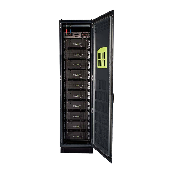
Page 28: Battery Storage
8.2 Battery storage TESVOLT TS The battery modules and the APU are delivered on pallets separate from the battery rack. The scope of delivery should be checked against the delivery note and the requirements under point 4 “Transport at end-customer site” and point 5 “Installation location”... -
Page 29: Apu-Unit Connections
BAT COM IN of the first battery module. WARNING! Installation and servicing may only be performed by qualified personnel. Only authorised TESVOLT GmbH personnel are permitted to open the APU-Unit. Improper use or incorrect configuration may damage the APU-Unit. -
Page 30: Installation Steps
The plug with an internal bridge from 1 to 2 is plugged into Rack Balancing Out. Connect the DC cable from the Sunny Island to the APU (CHARGER). If you do not use pre-assembled cables from TESVOLT, it is important that an earth leakage and short-circuit protected cable (such as NSGAFöU) be used. -
Page 31: Commissioning
OK. Now the battery is ready for use. online For systems with one Sunny Island, press the power button. For systems with three Sunny Islands, press and hold the power button on the master until you hear a signal tone. E.IA. .ENG- www.tesvolt.com... - Page 32 An audio signal tone is emitted 3 times and the SRC shows the "Quick Configuration Guide" (QCG). Turn the button on the SRC and select New System. Press the button. This selects the New System entry. Set Y and press the button. Set the Date. Set the Time. E.IA. .ENG- www.tesvolt.com...
- Page 33 14 Battery modules 15 Battery modules 16 Battery modules Set the operating mode: SelfConsOnly (self-consumption optimisation only), BackupOnly (backup power supply only), SelfConsBackup (self-consumption optimisation with backup power supply function). Set the Number of Sunny Islands in the system. E.IA. .ENG- www.tesvolt.com...
- Page 34 In the distribution system, close the power circuit breaker and residual current circuit breaker of the Sunny Island and leave the Sunny Island switched on but do not restart it. SMA, SUNNY ISLAND and SUNNYPORTAL are registered trademarks of SMA Solar Technology AG in many countries E.IA. .ENG- www.tesvolt.com...
- Page 35 Area for self consumption optimization 0-90% recommendation of on the shortest day of the year 80%, without Backup power supply) 100% SMA, SUNNY ISLAND and SUNNYPORTAL are registered trademarks of SMA Solar Technology AG in many countries E.IA. .ENG- www.tesvolt.com...
-
Page 36: Decommissioning
Remove the on/off switch plug from the BMS-Unit unit switch connector to prevent the unit from being unintentionally switched on again! Apply the REMOVE BEFORE supplied "REMOVE before commissioning" sticker to the APU-Unit unit switch START OPERATION connector to prevent the unit from being unintentionally switched on again. E.IA. .ENG- www.tesvolt.com... -
Page 37: Storage System Expansion
11 Storage system expansion The energy and the charge/discharge power of TESVOLT systems can be expanded. 11.1 Power expansion by SMA battery inverter System with one Sunny Island (single-phase) Charge/Discharge power per Cluster Max. 2,3 kW 1 x SI 3.0M Max. -
Page 38: Energy Expansion By Tesvolt Storage System
Islands and the battery. This distributes the power across the Sunny Islands via fuses. In a Cluster of three Sunny Islands, one Sunny Island functions as the Master that controls the other two Sunny Islands functioning as Slaves. 11.2 Energy expansion by TESVOLT storage system IMPORTANT! - Page 39 Example with 2 different clusters: Cluster 1: 3 x Sunny Island 6.0H (13,8 kW) with TS 40 Battery (up to 38,4 kWh) Cluster 2: 3 x Sunny Island 8.0H (18,0 kW) with 4 x TS 40 Battery (up to 153,6 kWh) E.IA. .ENG- www.tesvolt.com...
-
Page 40: Remote Monitoring Via Sunny Portal
All further steps are described in detail on the website. You will need the information on the type plate of the Sunny Home Manager for this. SMA, SUNNY ISLAND and SUNNYPORTAL are registered trademarks of SMA Solar Technology AG in many countries E.IA. .ENG- www.tesvolt.com... -
Page 41: Menu Structure Of Batterie Monitoring (Batmon)
The battery parameters are password Battery Output protected. Since these parameters directly Battery voltage affect the battery, only TESVOLT certified technical specialists are permitted to Charge/Discharge configure these parameters. You can obtain Battery temperature the password by directly requesting it from TESVOLT GmbH. -
Page 42: Battery System Error And Warning Messages
14 Battery system error and warning messages In the case of persistent errors please contact the TESVOLT Service Line. Fault correction Event Description Check the functionality of the 4 A BMS Fuse (F1) Storage system fails – microfuse mounted on the front side of the BMS-Unit to start and replace it if necessary. -
Page 43: Maintenance And Storage
15 Maintenance and storage The Lithium-Ion cells used by TESVOLT are maintenance-free. However, to ensure hazard-free operation, qualified specialists should check all connections and screws and tighten them where necessary since temperature fluctuations may loosen the screws. Check the tightening torque of the following screws: Battery pole: 12 Nm APU connection"Battery"... -
Page 44: Disposal
17 Disposal TESVOLT products are integrated in a free of charge disposal return system. Please contact TESVOLT in this regard. The batteries may only be disposed of in accordance with the disposal regulations for old batteries applicable at the time of disposal. - Page 46 WE HAVE A THEN FOR ANY WHEN TESVOLT GmbH Your certified TESVOLT partner Tel. +49 (0) 3491 8797 - 100 Am Alten Bahnhof 10 Email support@tesvolt.com 06886 Lutherstadt Wittenberg www.tesvolt.com Deutschland | Germany...
Need help?
Do you have a question about the TS Series and is the answer not in the manual?
Questions and answers