Advertisement
Quick Links
SparkFun Inventor's Kit for micro:bit
Experiment Guide
Introduction to the SparkFun Inventor's Kit for micro:bit
The SparkFun Inventor's Kit for micro:bit Experiment Guide is your map for navigating the waters of
beginning embedded electronics, robotics and citizen science using the micro:bit. This guide
contains all the information you will need to explore the 12 circuits of the SparkFun Inventors Kit for
micro:bit. At the center of this guide is one core philosophy — that anyone can (and should)
experiment with cutting-edge electronics in a fun and playful way without breaking the bank.
When you're done with this guide, you'll have the know-how to start creating your own projects and
experiments. From building robots and game controllers to data logging, the world will be your
oyster. Now enough talking — let's start tinkering!
SparkFun Inventor's Kit for micro:bit
K I T - 1 4 5 4 2
Advertisement

Subscribe to Our Youtube Channel
Related Manuals for Sparkfun Electronics Inventor's Kit

Summary of Contents for Sparkfun Electronics Inventor's Kit
- Page 1 SparkFun Inventor's Kit for micro:bit Experiment Guide Introduction to the SparkFun Inventor's Kit for micro:bit The SparkFun Inventor’s Kit for micro:bit Experiment Guide is your map for navigating the waters of beginning embedded electronics, robotics and citizen science using the micro:bit. This guide contains all the information you will need to explore the 12 circuits of the SparkFun Inventors Kit for micro:bit.
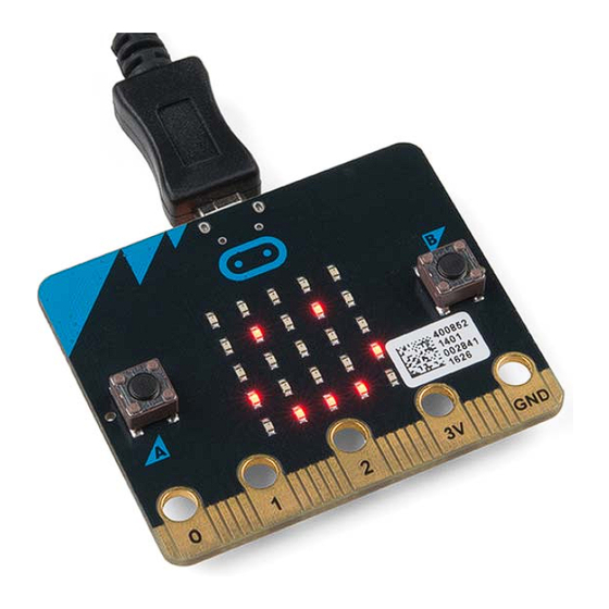
- Page 2 SparkFun Inventor's Kit for micro:bit Lab Pack L A B - 1 4 3 0 1 Included Materials The SparkFun Inventor’s Kit (SIK) for micro:bit includes the following: micro:bit — The brains of the outfit with a bunch of onboard components.
- Page 3 Red, Blue, Yellow, and Green LEDs — Light-Emitting Diodes make great general indicators. Momentary Pushbutton Switch — Go crazy with buttons. 10kΩ Trimpot — Also known as a variable resistor, this is a device commonly used to control volume and contrast, and makes a great general user control input.
- Page 4 To view a copy of this license visit this link, or write: Creative Commons, 171 Second Street, Suite 300, San Francisco, CA 94105, USA. What is the micro:bit? Introduction The micro:bit is a pocket-sized computer that lets you get creative with digital technology. You can code, customize and control your micro:bit from anywhere! You can use your micro:bit for all sorts of unique creations, from robots to musical instruments and more.
- Page 5 What is on the Board? The micro:bit has a lot to offer when it comes to onboard inputs and outputs. In fact, there are so many things packed onto this little board that you would be hard-pressed to really need anything else if your goal is to explore the basics of programming and hardware.
- Page 6 2. Accelerometer/Compass — The micro:bit has an onboard accelerometer that measures gravitational force, as well as a compass that can detect its orientation using Earth’s magnetic field. 3. Bluetooth/Radio — Communication is huge with the micro:bit. You can communicate with your phone or tablet using BLE or between two or more micro:bits using the standard “radio.”...
- Page 7 If you are on a Chromebook, when you plug your micro:bit in you will be greeted with a dialog box to open the drive. Feel free to do so to make sure it works! Introduction to Microsoft MakeCode What is MakeCode? MakeCode is an open programming environment built by Microsoft for the micro:bit, as well as other boards.
- Page 8 Let’s take a quick tour and check out what is available to us! 1. Projects — A cloud storage system connected to your computer with no account setup required. 2. Share — Allows you to share your project code in a number of different ways with your friends! 3.
- Page 9 The simulator will update as you build your code, and if you want to run it from the beginning you can click the stop and run buttons to start it over again! Speaking of code, let’s write a quick program and get it onto your micro:bit! Experiment 0: Hello, micro:bit! Introduction “Hello World”...
- Page 10 We are going to use the block for building this “Hello World.” We now need to start adding forever blocks to forever First, click on the Basics category. These blocks are, well, the basic building blocks of a BuildCode program. It will expand into a number of options. Click and drag the block over and place it show leds inside of your...
- Page 11 To turn this static image into an animation, we need another block to place just under the show leds first block. You can then make a second drawing with this set of rectangles. In your simulator you will see the images switching really, really fast. We need to slow this down! To slow your animation down, you will use the block, which is under the basic block set.
- Page 12 We have built up an example in the next section where you can download the file and try it out on your own micro:bit, or use the simulator. If you want to play around with the code and make some changes, go ahead and click the Edit button in the widget, and it will open a MakeCode editor for you to start hacking “Hello World.”...
- Page 13 Parts Needed You will need the following parts: 1x micro:bit 1x Micro B USB Cable 1x micro:bit Breakout (with Headers) 1x Breadboard 1x Jumper Wire 1x LED 1x 100Ω Resistor Didn’t Get the SIK for micro:bit? If you are conducting this experiment and didn’t get the Inventor’s Kit, we suggest using these parts: Breadboard - Full-Size (Bare) P R T - 1 2 6 1 5...
-
Page 14: Table Of Contents
SparkFun micro:bit Breakout (with Headers) B O B - 1 3 9 8 9 Jumper Wires Standard 7" M/M - 30 AWG (30 Pack) P R T - 1 1 0 2 6 LED - Basic Red 5mm C O M - 0 9 5 9 0 Resistor 100 Ohm 1/4 Watt PTH - 20 pack (Thick Leads) P R T - 1 4 4 9 3... - Page 15 Suggested Reading Before continuing with this experiment, we recommend you be familiar with the concepts in the following tutorial: Light-Emitting Diodes — Learn more about LEDs! How to Use a Breadboard — Learn the basics of using a breadboard! Introducing the micro:bit Breakout To extend the functionality of the micro:bit beyond what is already on the board, we developed a micro:bit breakout.
- Page 16 Introducing the LED A Light-Emitting Diode (LED) will only let current through in one direction. Think of an LED as a one- way street. When current flows through the LED, it lights up! When you are looking at the LED, you will notice that its legs are different lengths. The long leg, the “anode,”...
- Page 17 Components like resistors need to have their legs bent into 90° angles in order to correctly fit the breadboard sockets. You can also cut the legs shorter to make them easier to work with on the breadboard.
- Page 18 Wiring Diagram for the Experiment Having a hard time seeing the circuit? Click on the wiring diagram for a closer look. Running Your Script Either copy and paste, or re-create the following code into your own MakeCode editor by clicking the open icon in the upper right-hand corner of the editor.
- Page 19 Code to Note Let’s take a look at the code blocks in this experiment. If you are having a hard time viewing this code, click on the image above to get a better look! Forever block is a block that loops any other command blocks inserted into it over and over forever again…forever.
- Page 20 Troubleshooting LED Not Blinking Make sure you have it wired correctly and the correct pin to ground. Remember, short pin to ground; long pin to signal. Still No Success broken circuit is no fun. Send us an email, and we will get back to you as soon as we can: techsupport@sparkfun.com .
-
Page 21: Sparkfun Micro:bit Breakout (With Headers)
1x Breadboard 8x Jumper Wires 1x 10kΩ Potentiometer 1x LED 1x 100Ω Resistor Didn’t Get the SIK for micro:bit? If you are conducting this experiment and didn’t get the Inventor’s Kit, we suggest using these parts: Breadboard - Full-Size (Bare) P R T - 1 2 6 1 5 micro:bit Board... -
Page 22: Jumper Wires Standard 7" M/M - 30 Awg (30 Pack)
Trimpot 10K with Knob C O M - 0 9 8 0 6 Jumper Wires Standard 7" M/M - 30 AWG (30 Pack) P R T - 1 1 0 2 6 LED - Basic Red 5mm C O M - 0 9 5 9 0... -
Page 23: Resistor 100 Ohm 1/4 Watt Pth - 20 Pack (Thick Leads)
Resistor 100 Ohm 1/4 Watt PTH - 20 pack (Thick Leads) P R T - 1 4 4 9 3 Suggested Reading Before continuing with this experiment, we recommend you be familiar with the concepts in the following tutorial: Analog to Digital Conversion Introducing the Potentiometer A potentiometer is a resistance-based analog sensor that changes its internal resistance based on... - Page 24 Polarized Pay special attention to the component’s markings indicating how to place it on Components the breadboard. Polarized components can only be connected to a circuit in one direction. Wiring Diagram for the Experiment Having a hard time seeing the circuit? Click on the wiring diagram for a closer look. Note: The full sized breadboard power rails have a break down the middle. If you end up using the lower half of the power rail you will need to jump between the upper end and lower end.
- Page 25 Running Your Script Either copy and paste, or re-create the following code into your own MakeCode editor by clicking the open icon in the upper right-hand corner of the editor. You can also just download this example by clicking the download button in the lower right-hand corner of the code window. Note: You may need to disable your ad/pop-up blocker to interact with the MakeCode programming environment and simulated circuit! Code to Note...
- Page 26 Troubleshooting Sporadically Working This is most likely due to a slightly dodgy connection with the potentiometer’s pins. This can usually be conquered by holding the potentiometer down or moving the potentiometer circuit somewhere else on your breadboard. Not Working Make sure you haven’t accidentally connected the wiper (center pin), the resistive element in the potentiometer, to a wrong pin! LED Not Lighting Up LEDs will only work in one direction.
- Page 27 Parts Needed You will need the following parts: 1x micro:bit 1x Micro B USB Cable 1x micro:bit Breakout (with Headers) 1x Breadboard 8x Jumper Wires 1x Photoresistor 1x 10kΩ Resistor 1x LED ...
- Page 28 Mini Photocell S E N - 0 9 0 8 8 SparkFun micro:bit Breakout (with Headers) B O B - 1 3 9 8 9 Jumper Wires Standard 7" M/M - 30 AWG (30 Pack) P R T - 1 1 0 2 6 LED - Basic Red 5mm C O M - 0 9 5 9 0...
- Page 29 Resistor 10K Ohm 1/4 Watt PTH - 20 pack (Thick Leads) P R T - 1 4 4 9 1 Resistor 100 Ohm 1/4 Watt PTH - 20 pack (Thick Leads) P R T - 1 4 4 9 3 Introducing the Photoresistor The photoresistor changes its resistance based on the light to which it is exposed.
- Page 30 To use this with the micro:bit, you will need to build a voltage divider with a 10kΩ resistor, as shown in the wiring diagram for this experiment. The micro:bit cannot read a change in resistance, only a change in voltage. A voltage divider allows you to translate a change in resistance to a corresponding voltage value.
- Page 31 Note: The full sized breadboard power rails have a break down the middle. If you end up using the lower half of the power rail you will need to jump between the upper end and lower end. Running Your Script Either copy and paste, or re-create the following code into your own MakeCode editor by clicking the open icon in the upper right-hand corner of the editor.
- Page 32 What You Should See When the micro:bit runs the program it will take a single reading from the light sensor and use that as a calibration value of the “normal” state of the room. When you place your hand over the light sensor or turn the lights off, the LED will turn on.
- Page 33 Parts Needed You will need the following parts: 1x micro:bit 1x Micro B USB Cable 1x micro:bit Breakout (with Headers) 1x Breadboard 1x Jumper Wire 1x Common Cathode RGB LED 3x 100Ω Resistors Didn’t Get the SIK for micro:bit? If you are conducting this experiment and didn’t get the Inventor’s Kit, we suggest using these parts: Breadboard - Full-Size (Bare)
- Page 34 SparkFun micro:bit Breakout (with Headers) B O B - 1 3 9 8 9 Jumper Wires Standard 7" M/M - 30 AWG (30 Pack) P R T - 1 1 0 2 6 LED - RGB Diffused Common Cathode C O M - 0 9 2 6 4 Resistor 100 Ohm 1/4 Watt PTH - 20 pack (Thick Leads) P R T - 1 4 4 9 3...
- Page 35 Introducing the Red/Green/Blue (RGB) LED The Red/Green/Blue (RGB) LED is three LEDs in one. The RGB has four pins with each of the three shorter pins controlling an individual color: red, green or blue. The longer pin of the RGB is the common ground pin.
- Page 36 Hardware Hookup Ready to start hooking everything up? Check out the wiring diagram and hookup table below to see how everything is connected. Polarized Pay special attention to the component’s markings indicating how to place it on Components the breadboard. Polarized components can only be connected to a circuit in one direction. Wiring Diagram for the Experiment Having a hard time seeing the circuit? Click on the wiring diagram for a closer look.
- Page 37 Run Your Script Either copy and paste, or re-create the following code into your own MakeCode editor by clicking the open icon in the upper right-hand corner of the editor. You can also just download this example by clicking the download button in the lower right-hand corner of the code window. Note: You may need to disable your ad/pop-up blocker to interact with the MakeCode programming environment and simulated circuit! Code to Note...
- Page 38 Troubleshooting LED Remains Dark or Shows Incorrect Color With the four pins of the LED so close together, it’s sometimes easy to misplace one. Double check that each pin is where it should be. Seeing Red The red diode within the RGB LED may be a bit brighter than the other two. To make your colors more balanced, use a higher ohm resistor.
- Page 39 Didn’t Get the SIK for micro:bit? If you are conducting this experiment and didn’t get the Inventor’s Kit, we suggest using these parts: Breadboard - Full-Size (Bare) P R T - 1 2 6 1 5 micro:bit Board D E V - 1 4 2 0 8 SparkFun micro:bit Breakout (with Headers) B O B - 1 3 9 8 9...
- Page 40 Jumper Wires Standard 7" M/M - 30 AWG (30 Pack) P R T - 1 1 0 2 6 Mini Power Switch - SPDT C O M - 0 0 1 0 2 LED - Basic Red 5mm C O M - 0 9 5 9 0 LED - Basic Yellow 5mm C O M - 0 9 5 9 4...
- Page 41 Resistor 100 Ohm 1/4 Watt PTH - 20 pack (Thick Leads) P R T - 1 4 4 9 3 Suggested Reading Before continuing with this tutorial, we recommend you be somewhat familiar with the concepts in these tutorials: Switch Basics ...
- Page 42 Hardware Hookup Ready to start hooking everything up? Check out the wiring diagram and hookup table below to see how everything is connected. Polarized Pay special attention to the component’s markings indicating how to place it on Components the breadboard. Polarized components can only be connected to a circuit in one direction. Wiring Diagram for the Experiment Having a hard time seeing the circuit? Click on the wiring diagram for a closer look.
- Page 43 Note: The full sized breadboard power rails have a break down the middle. If you end up using the lower half of the power rail you will need to jump between the upper end and lower end. Run Your Script Either copy and paste, or re-create the following code into your own MakeCode editor by clicking the open icon in the upper right-hand corner of the editor window.
- Page 44 What You Should See Depending on the state of the switch, a different LED will blink. If you move the switch to connect the signal pin to 3.3V (HIGH), then the LED connected to pin P15 will blink. If you flip the switch and ground the signal pin, then the LED on pin P16 will start blinking and LED 1 will turn off.
- Page 45 Experiment 6: Reading a Button Press Introduction Up until now, we’ve focused mostly on outputs. Now we’re going to go to the other end of the spectrum and play around with inputs. In Experiment 2, we used an analog input to read the potentiometer.
- Page 46 SparkFun micro:bit Breakout (with Headers) B O B - 1 3 9 8 9 Jumper Wires Standard 7" M/M - 30 AWG (30 Pack) P R T - 1 1 0 2 6 Multicolor Buttons - 4-pack P R T - 1 4 4 6 0 LED - RGB Diffused Common Cathode C O M - 0 9 2 6 4...
- Page 47 Resistor 10K Ohm 1/4 Watt PTH - 20 pack (Thick Leads) P R T - 1 4 4 9 1 Resistor 100 Ohm 1/4 Watt PTH - 20 pack (Thick Leads) P R T - 1 4 4 9 3 Suggested Reading Before continuing with this experiment, we recommend you be somewhat familiar with the concepts in these tutorials:...
- Page 48 How do you know which pins are paired up? The buttons included in this kit will only fit across the breadboard ditch in one direction. Once you get the button pressed firmly into the breadboard (across the ditch), the pins are horizontally paired. The pins toward the top of the breadboard are connected, and the pins toward the button of the breadboard are connected.
- Page 49 Wiring Diagram for the Experiment Having a hard time seeing the circuit? Click on the wiring diagram for a closer look. Note: The full sized breadboard power rails have a break down the middle. If you end up using the lower half of the power rail you will need to jump between the upper end and lower end.
- Page 50 Code to Note Let’s take a look at the code blocks in this experiment. If you are having a hard time viewing this code, click on the image above to get a better look! Set Pull Pin When you start your micro:bit, some pins can be set to be naturally on or naturally off. The set pull ...
- Page 51 On Event Under the Advanced blocks you can find the Control blocks. These are the blocks that are the most complicated to use, but are the most powerful. The block accepts an event type to watch On Event for and a pin that event should happen on. When that specific event is emitted from that pin, it will trigger whatever code is inside of it.
- Page 52 While the image shows a black momentary pushbutton, you can use any colored button as long as it is momentary pushbutton to cycle through the colors! Troubleshooting Light Not Turning On The push button is square, and because of this it is easy to put it in the wrong way. Give it a 90- degree twist and see if it starts working.
- Page 53 Parts Needed You will need the following parts: 1x micro:bit 1x Micro B USB Cable 1x micro:bit Breakout (with Headers) 1x Breadboard 5x Jumper Wires 1x TMP36 Temperature Sensor Didn’t Get the SIK for micro:bit? If you are conducting this experiment and didn’t get the Inventor’s Kit, we suggest using these parts: Breadboard - Full-Size (Bare) P R T - 1 2 6 1 5...
- Page 54 SparkFun micro:bit Breakout (with Headers) B O B - 1 3 9 8 9 Jumper Wires Standard 7" M/M - 30 AWG (30 Pack) P R T - 1 1 0 2 6 Temperature Sensor - TMP36 S E N - 1 0 9 8 8 Introducing the TMP36 Temperature Sensor The TMP36 is a low-voltage precision centigrade temperature sensor.
- Page 55 If you are looking at the flat face with text on it, the center pin is your signal pin, the left-hand pin is supply voltage (3.3V in this tutorial), and the right-hand pin connects to ground. Pro Tip: The TMP36 looks a lot like a transistor. Put a dot of fingernail polish on the top of your TMP36 so it’s easy to find.
- Page 56 Wiring Diagram for the Experiment Having a hard time seeing the circuit? Click on the wiring diagram for a closer look. Run Your Script Either copy and paste, or re-create the following code into your own MakeCode editor by clicking the open icon in the upper right-hand corner of the editor window.
- Page 57 Code to Note Let’s take a look at the code blocks in this experiment. If you are having a hard time viewing this code, click on the image above to get a better look! Adding an External Package In MakeCode you can write external pieces of code that allows you to create and use custom blocks for specific applications and/or components that you could use with the micro:bit.
- Page 58 Once you select the TMP36 package there should be a TMP36 code block drawer to select from in your blocks menu. This drawer has only one block in it and that is a block that returns the temperature from a TMP36 sensor connected to a specific pin in fahrenheit or celcius.
- Page 59 Troubleshooting Temperature Value is Unchanging Try pinching the sensor with your fingers to heat it up or pressing a bag of ice against it to cool it down. Temperature Sensor is Really Hot! You have wired it backward! Unplug your micro:bit immediately, let the sensor cool down, and double-check your wiring.
- Page 60 Servo - Generic (Sub-Micro Size) R O B - 0 9 0 6 5 Breadboard - Full-Size (Bare) P R T - 1 2 6 1 5 micro:bit Board D E V - 1 4 2 0 8 SparkFun micro:bit Breakout (with Headers) B O B - 1 3 9 8 9...
- Page 61 Jumper Wires Standard 7" M/M - 30 AWG (30 Pack) P R T - 1 1 0 2 6 Suggested Reading Before continuing with this experiment, we recommend you be familiar with the concepts in the following tutorial: Pulse Width Modulation Introducing the Servo Motor Unlike the action of most motors that continuously rotate, a servo motor can rotate to and hold a specific angle until it is told to rotate to a different angle.
- Page 62 Inside of the servo there is a gearbox connected to a motor that drives the shaft. There is also a potentiometer that gives feedback on the rotational position of the servo, which is then compared to the incoming PWM signal. The servo adjusts accordingly to match the two signals. In this experiment, the servo is powered through 3.3 volts on the red wire and ground on the black wire;...
- Page 63 Run Your Script Either copy and paste, or re-create the following code into your own MakeCode editor by clicking the open icon in the upper right-hand corner of the editor window. You can also just download this example by clicking the download button in the lower right-hand corner of the code window. Note: Controlling a servo with the micro:bit is not intended to give you a highly accurate angle of rotation, just basic movement from one position to another to get your project movin'.
- Page 64 What You Should See When powered up you should see the servo move to a single location (0 degrees) and then start to sweep to 180 degrees back and forth until you turn it off or tell it to go to a different angle. Troubleshooting Servo Not Twisting Even with colored wires, it is still shockingly easy to plug a servo in backward.
- Page 65 Didn’t Get the SIK for micro:bit? If you are conducting this experiment and didn’t get the Inventor’s Kit, we suggest using these parts: Breadboard - Full-Size (Bare) P R T - 1 2 6 1 5 micro:bit Board D E V - 1 4 2 0 8 SparkFun micro:bit Breakout (with Headers) B O B - 1 3 9 8 9...
- Page 66 Jumper Wires Standard 7" M/M - 30 AWG (30 Pack) P R T - 1 1 0 2 6 Mini Speaker - PC Mount 12mm 2.048kHz C O M - 0 7 9 5 0 Multicolor Buttons - 4-pack P R T - 1 4 4 6 0 Resistor 10K Ohm 1/4 Watt PTH - 20 pack (Thick Leads) P R T - 1 4 4 9 1...
- Page 67 Introducing the Piezo Buzzer The buzzer is a small component with a piece of metal in it that moves when you apply a voltage across it. This motion causes a small sound, or “click.” If you turn the voltage on and off fast enough, you get different beeps, squeals, chirps and buzzes. You will use PWM to control the speed of turning the piezo on and off —...
- Page 68 Polarized Pay special attention to the component’s markings indicating how to place it on Components the breadboard. Polarized components can only be connected to a circuit in one direction. Wiring Diagram for the Experiment Having a hard time seeing the circuit? Click on the wiring diagram for a closer look. Note: The full sized breadboard power rails have a break down the middle. If you end up using the lower half of the power rail you will need to jump between the upper end and lower end.
- Page 69 Run Your Script Either copy and paste, or re-create the following code into your own MakeCode editor by clicking the open icon in the upper right-hand corner of the editor window. You can also just download this example by clicking the download button in the lower right-hand corner of the code window. Note: You may need to disable your ad/pop-up blocker to interact with the MakeCode programming environment and simulated circuit! Code to Note...
- Page 70 While the image shows black momentary pushbuttons, you can use any colored button as long as it is momentary pushbutton to trigger the sounds! Troubleshooting No Sound Given the size and shape of the piezo buzzer, it is easy to miss the right holes on the breadboard. Try double-checking its placement.
- Page 71 Didn’t Get the SIK for micro:bit? If you are conducting this experiment and didn’t get the Inventor’s Kit, we suggest using these parts: Servo - Generic (Sub-Micro Size) R O B - 0 9 0 6 5 Breadboard - Full-Size (Bare) P R T - 1 2 6 1 5 micro:bit Board D E V - 1 4 2 0 8...
- Page 72 SparkFun micro:bit Breakout (with Headers) B O B - 1 3 9 8 9 Jumper Wires Standard 7" M/M - 30 AWG (30 Pack) P R T - 1 1 0 2 6 Introducing the Accelerometer The accelerometer is a component that you won’t find in the kit’s bag of parts. Why? Because it is on the micro:bit itself! On the back of the micro:bit you can see a number of small chips.
- Page 73 Not only can an accelerometer measure the raw forces pulling on the chip and the object that the chip is sitting on, but it can also detect steps, shakes and other motions that have a specific pattern. On top of that, you can use an accelerometer to simply detect the orientation that the device is in. Did you ever wonder how your phone knows when you turn it from portrait to landscape? It is all because of the accelerometer in your phone! Hardware Hookup...
- Page 74 Wiring Diagram for the Experiment Having a hard time seeing the circuit? Click on the wiring diagram for a closer look. Run Your Script Either copy and paste, or re-create the following code into your own MakeCode editor by clicking the open icon in the upper right-hand corner of the editor window.
- Page 75 Code to Note Let’s take a look at the code blocks in this experiment. If you are having a hard time viewing this code, click on the image above to get a better look! Acceleration block can be found under the input blocks group. This block returns the force of acceleration gravity pulling on a specific axis of the micro:bit (X, Y or Z) and represents that value as a range of numbers between -1023 and 1023.
- Page 76 Troubleshooting This Seems Backward You may be holding the micro:bit in a different orientation. Flip it around and try again! Servo Isn’t Working Double-check your wiring! Remember, red to 3.3 volts, black to ground, and white to signal. Experiment 11: Using the Compass Introduction This experiment is just plain fun! Have you ever used a compass? Are you a little confused in terms of which direction to go? Fear not! We will build a digital compass that will keep you on track to the...
- Page 77 Didn’t Get the SIK for micro:bit? If you are conducting this experiment and didn’t get the Inventor’s Kit, we suggest using these parts: Breadboard - Full-Size (Bare) P R T - 1 2 6 1 5 micro:bit Board D E V - 1 4 2 0 8 SparkFun micro:bit Breakout (with Headers) B O B - 1 3 9 8 9...
- Page 78 Jumper Wires Standard 7" M/M - 30 AWG (30 Pack) P R T - 1 1 0 2 6 LED - Basic Red 5mm C O M - 0 9 5 9 0 Resistor 100 Ohm 1/4 Watt PTH - 20 pack (Thick Leads) P R T - 1 4 4 9 3 Suggested Reading Before continuing with this experiment, we recommend you be familiar with the concepts in the...
- Page 79 The magnetometer detects magnetic north and then represents your heading in degrees with north being 0 degrees, east being 90 degrees, south being 180 degrees and west being 270. Pretty cool! Now let’s put this compass to good use! Hardware Hookup Ready to start hooking everything up? Check out the wiring diagram below to see how everything is connected.
- Page 80 Wiring Diagram for the Experiment Having a hard time seeing the circuit? Click on the wiring diagram for a closer look. Note: The full sized breadboard power rails have a break down the middle. If you end up using the lower half of the power rail you will need to jump between the upper end and lower end.
- Page 81 Code to Note Let’s take a look at the code blocks in this experiment. If you are having a hard time viewing this code, click on the image above to get a better look! Compass Heading block returns the heading that you are facing if you are holding the micro:bit flat compass heading with the pins toward you.
- Page 82 Note: If you calibrate your micro:bit while inside and in a proximity to your computer or something that produces a larger magnetic field it will skew your micro:bits sense of direction. You will end up creating a metal detector rather than a compass! Troubleshooting Not Really North? You may have a motor or magnet close by! The magnetometer is sensitive to all magnetic fields,...
- Page 83 micro:bot Kit Experiment Guide Get started with the moto:bit, a carrier board for the micro:bit that allows you to control motors, and create your own robot using this experiment guide for the micro:bot kit. micro:arcade Kit Experiment Guide We love games! We love writing games, building games and yes, even building game consoles.
Need help?
Do you have a question about the Inventor's Kit and is the answer not in the manual?
Questions and answers