Advertisement
Quick Links
Use
CC1N7785en
15.10.2003
Burner Controls
Burner controls with self-checking flame signal amplifier, for continuously oper-
ating multistage or modulating oil or gas burners of medium to high capacity;
with air pressure supervision for checked air damper control.
The LOK16... / LGK16... and this Data Sheet are intended for use by OEMs which
integrate the burner controls in their products.
Burner controls type LOK16... / LGK16... feature a self-checking flame supervision cir-
cuit.
The supervision circuit initiates the required safety actions not only in the case of pre-
mature or missing flame signals, but also in the event of any kind of fault on the flame
detector, the detector cables or the flame signal amplifier that could simulate a flame
signal during burner operation.
Siemens Building Technologies
HVAC Products
7
785
LOK16...
LGK16...
Advertisement

Related Manuals for Siemens LOK16 Series


Summary of Contents for Siemens LOK16 Series
- Page 1 Siemens Building Technologies CC1N7785en HVAC Products...
- Page 2 Do not press the lockout reset button on the unit or the remote reset button (input 21) for more than 10 seconds, since this would damage the lockout re- lay inside the unit 2/20 Siemens Building Technologies CC1N7785en HVAC Products 15.10.2003...
- Page 3 «t9». At the end of the second safety time, one of the detected flames must extinguish, e.g. by shutting down the pilot gas valve connected to ter- minal 17 3/20 Siemens Building Technologies CC1N7785en HVAC Products 15.10.2003...
- Page 4 Each time a unit has been replaced, check to ensure that wiring is in an orderly state. Make the safety check in accordance with section «Commissioning notes» • The KF8832 flame detector current measuring instrument may not be used in con- tinuous operation 4/20 Siemens Building Technologies CC1N7785en HVAC Products 15.10.2003...
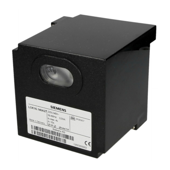
- Page 5 Housing and plug-in base are made of shock- and heat-resistant black plastic. The lockout indicator, fault signal lamp and lockout reset button are located in the unit’s viewing window. The burner control has an exchangeable unit fuse and a spare fuse. 5/20 Siemens Building Technologies CC1N7785en HVAC Products 15.10.2003...
- Page 6 D, A F, I B, NL generators generators for direct-fired air heaters), LGK16.122A27* LGK16.133A27 LGK16.322A27* LGK16.333A27* LGK16.335A27* LGK16.622A27* LGK16.635A27* 31.5 37.5 67.5 TSA´ t3´ 12.5 12.5 t4´ 12.5 12.5 14.5 Optional Optional 22.5 6/20 Siemens Building Technologies CC1N7785en HVAC Products 15.10.2003...
- Page 7 Accessories for flame Refer to Data Sheet 7712 detectors For burner controls operating on AC 100...110 V, 50...60 Hz, the last 2 digits of the type reference read «17» in place of «27» 7/20 Siemens Building Technologies CC1N7785en HVAC Products 15.10.2003...
- Page 8 • If possible, shielding should be earthed at both ends Longer cable distances are permitted when connecting low capacitance detector cables to terminal 24 of the burner control (especially against earthed wires!) 8/20 Siemens Building Technologies CC1N7785en HVAC Products 15.10.2003...
- Page 9 «LR» at terminal 20. The sequence switch switches itself automatically off, depend- ing on the time variant used, either immediately or after some so-called «idle steps», that is, without changing the contact positions. 9/20 Siemens Building Technologies CC1N7785en HVAC Products 15.10.2003...
- Page 10 However, during the burner off period, lockout can occur only if the faulty flame signal lasts a few seconds. Hence, short ignition pulses of the UV detector caused by cosmic radiation do not initiate lockout. 10/20 Siemens Building Technologies CC1N7785en HVAC Products 15.10.2003...
- Page 11 Only with LOK16...: If wire link «B» was cut off and the flame is lost during burner operation, the burner control programs a repetition of the startup sequence with the full program. 11/20 Siemens Building Technologies CC1N7785en HVAC Products 15.10.2003...
- Page 12 9, 10 and 11 receive power in accordance with the control sequence. It is only then that the burner control programs a burner restart. Note: Do not press the lockout reset button for more than 10 seconds. 12/20 Siemens Building Technologies CC1N7785en HVAC Products 15.10.2003...
-
Page 13: Assignment Of Terminals
Gas pressure switch Limit thermostat or pressure switch Mains isolator In the air damper actuator: End switch for L... Lockout warning lamp the air damper’s fully closed position Air damper Ignition transformer Pilot valve 13/20 Siemens Building Technologies CC1N7785en HVAC Products 15.10.2003... - Page 14 Postpurge time (identical with the permissible max. Safety time in the event of loss of flame afterburn time «t13») during operation Times TSA´, t3´ and t4´ are only programmed by burner controls LGK16.335... and LGK16.635... 14/20 Siemens Building Technologies CC1N7785en HVAC Products 15.10.2003...
-
Page 15: Connection Diagrams
2) Do not press EK for more than 10 seconds Control output at terminal: VIII *t4´ *t3´ *TSA´ t1 0 t1 3 XIII 7785d03e/0102 Lockout indication position Times TSA´, t3´ and t4´ are only programmed by burner controls LGK16.335... and LGK16.635... 15/20 Siemens Building Technologies CC1N7785en HVAC Products 15.10.2003... - Page 16 VIII XIII 19 9 11 10 1 (3) 7785a07/1001 2) Do not press EK for more than 10 seconds Control output at terminal: t3´ t2 0 VIII XIII 7785d04e/0102 Lockout indication position 16/20 Siemens Building Technologies CC1N7785en HVAC Products 15.10.2003...
- Page 17 The relay is not required if the valve connected to terminal 7785a10/0396 20 is hydraulically series-connected to a valve controlled by terminal 18 or 19. If no air damper actuator is used, terminal 8 must be con- nected to terminal 6. 17/20 Siemens Building Technologies CC1N7785en HVAC Products 15.10.2003...
- Page 18 With QRA5x.D... 300 µA 100 µA 7785v04/1001 7785v01/1096 470 µF/25 V 470 µF/25 V With RAR... With ionization 25 µA 100 µA RAR... 7785v03/0903 7785v02/0497 Legend Ammeter RAR... Selenium photocell detector Ionization probe 18/20 Siemens Building Technologies CC1N7785en HVAC Products 15.10.2003...
- Page 19 LGK16.335 or LGK16.635, for example. The other types of burner controls of the LGK16... range program the times «TSA», «t3», «t4» and «t9» for the pilot burner. t3´ TSA´ t4´ 100% min. 0... 7785d02/1001 19/20 Siemens Building Technologies CC1N7785en HVAC Products 15.10.2003...
- Page 20 Dimensions in mm LOK16... / LGK16... with plug-in base AGM... 18,9 7785m02/0296 27,5 27,5 13,5 18,5 5,2x6,7 AGM16... or AGM17... 18,9 5,2x6,7 7785m01/0296 12,8 51,5 51,5 ©2003 Siemens Building Technologies Subject to change 20/20 Siemens Building Technologies CC1N7785en HVAC Products 15.10.2003...
Need help?
Do you have a question about the LOK16 Series and is the answer not in the manual?
Questions and answers