
Related Manuals for Wenglor BLN0 1R10 Series


Summary of Contents for Wenglor BLN0 1R10 Series
- Page 1 BLN0x1R10 Scanner 1D – CCD array Operating Instructions Available as PDF file only Status: 27.11.2017 Version: 1.6 www.wenglor.com...
-
Page 2: Table Of Contents
Index Proper Use Safety Precautions Approvals and protection class Technical Data 4.1. Scanner Connection 4.2. Housing Dimensions 4.3. Control Panel 4.4. Complementary Products (see catalog) Mounting Instructions Initial Operation 6.1. Initial Operation Function Descriptions 7.1. Run 7.2. Pin Function 7.3. E/A Settings 7.3.1. - Page 3 7.9. Display 7.9.1. Display – Mode 7.9.2. Display – Intensity 7.10. Language 7.11. Info 7.12. Reset 7.13. Password Network Settings Web-Based Configuration 9.1. Invoking the Administration Interface 9.2. Overview Page 9.3. Device Settings 9.4. Read Cycle 9.4.1. Reading mode 9.4.3. Code 9.4.4.
-
Page 4: Proper Use
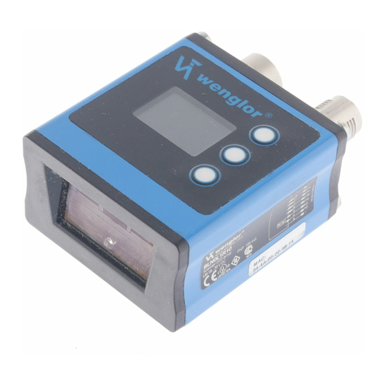
1. Proper Use This wenglor product has to be used according to the following functional principle: Scanner 1D These Scanners detect 1D Codes with the help of Laser Light respectively Red Light. The light sent out to the barcode label is reflected back to a photo element and evaluated with a decoder. -
Page 5: Technical Data
4. Technical Data Order Number BLN0L1R10 BLN0H1R10 Light Source Red Light Red Light Wave Length 660 nm 660 nm Low Density High Density Read Range 35...320 mm 10...120 mm max. Ambient Light 7000 Lux 7000 Lux Opening Angle 35° 60° Barcode Label Contrast 45 % 45 %... -
Page 6: Scanner Connection
Scanning Distance Diagram: Low Density High Density in mm in mm 0.380 0.508 0.254 0.254 0.127 0.127 BLN0L1R10 BLN0H1R10 4.1. Scanner Connection Supply Voltage „+“ – Supply Voltage „0 V“ Output/Input programmable RS-232 receive path RS-232 send path Tx+/– Ethernet send path Rx+/–... -
Page 7: Housing Dimensions
4.2. Housing Dimensions 4.3. Control Panel 20 = Enter Button 22 = Up Button 23 = Down Button 60 = Display... -
Page 8: Complementary Products (See Catalog)
4.4. Complementary Products (see catalog) wenglor offers Connection Technology for field wiring. Suiting Connection Technology No. Connector cable M12×1, 8-pin (plug 1) ZAS89R201, M12×1 connector cable, 8-pin, 2 m, straight ZAS89R202, M12×1 connector cable, 8-pin, 2 m, angled ZAS89R501, M12×1 connector cable, 8-pin, 5 m, straight ZAS89R502, M12×1 connector cable, 8-pin, 5 m, angled... -
Page 9: Mounting Instructions
5. Mounting Instructions All applicable electrical and mechanical regulations, standards and safety precautions must be adhered to when installing and operating the scanner. The scanner must be protected against mechanical influences. Install the product such that its installation position cannot be inadvertently changed. 6. -
Page 10: Function Descriptions
7. Function Descriptions Good Read E/A1 No Read E/A2 Match Pin Function E/A3 Mismatch Trigger Input E/A4 New Master Depends on pin function E/A1: Pushpull A1 Good Read NPN/PNP A1 No Read NO/NC If switching output A1 Match E/A configure ON Delay Value in ms A 1 Mismatch... - Page 11 Code39 Code Settings Interleaved2/5 Codabar Code32 MSI Plessy Code11 Industrial2/5 Matrix2/5 Telepen UKPlessy Code93 EAN-13 EAN-8 UPC-A UPC-E Code128 EAN-128 RSS-14 ON/OFF New match code Matchcode New match code is read in Match code Current matchcode 9600 is displayed 19200 38400 Serial Baude rate...
-
Page 12: Pin Function
Which functions can be executed with the individual menu options is explained below. 7.1. Run The Scanner is switched to the display mode when the enter key is pressed. 7.2. Pin Function The pin function is used to specify the function assigned to pins E/A1 through E/A4. Various functions can be assigned to the pin. - Page 13 For No Read A1 No Read/ A2 No Read/ Basic Scanner settings for the individual switching outputs are entered to the A3 No Read/ A1/A2/A3/A4 No Read menu. A4 No Read NPN/PNP NPN/PNP: Output configuration NO/NC NO/NC: Output configuration ON Delay ON Delay: ON Delay OFF Delay...
-
Page 14: Output - Npn/Pnp
For Trigger Input When a pin is configured as a trigger input, the following functions can be set up: E1 Trigger/ E2 Trigger/ Basic Scanner settings for the individual inputs are entered to the E1/E2/E3/E4 E3 Trigger/ Trigger menu. E4 Trigger At Ub: The input is activated when supply power (Ub) is on. -
Page 15: Output - On Delay
7.3.3. Output – ON Delay ON Delay is an adjustable extension of response time. Code Output ON Delay ON Delay Adjusting ON Delay ON Delay in ms ON Delay can be adjusted within a range of 0 to 1000 ms by pressing the “+” or “–”... -
Page 16: Output - Pulse Length
7.3.5. Output – Pulse Length Pulse Length defines the duration of the switching status. This function can be combined with ON Delay. Code Pulse Length Impulse ON Delay Pulse combined with ON Delay Pulse Length Impulse Adjusting Pulse Length Pulse Length in ms Pulse duration can be adjusted within a range of 0 to 1000 ms by pressing the “+”... -
Page 17: A-Test - Testing E1 Through E4
7.4.2. E/A-Test – Testing E1 through E4 Test E1/Test E2/ Activating or Deactivating Inputs Test E3/Test E4 Symbol The symbol indicates the input’s state. Back 7.5. Reading mode The reading mode function determines the Scanner’s reading performance. Reading mode The Scanner’s reading performance is defined in the Reading Mode menu. Trigger Trigger: The Scanner starts the reading procedure after receiving a trigger... -
Page 18: Code Settings
7.6. Code Settings Available code algorithms can be activated or deactivated with the Code Settings menu. Code Settings Various code algorithms can be activated in the Code Settings menu. Code 39 Activates or deactivates the respective code algorithm. The respective codes are Interleaved 2/5 described in more detail beginning with section “9.5. -
Page 19: Serial/Baude Rate
7.8.1. Serial/Baude rate Baude rate Setting the Baude rate 9600 9600: 9600 Baud (default setting) 19200 19200: 19200 Baud 38400 38400: 38400 Baud 115200 115200: 115200 Baud Back 7.8.2. Ethernet Ethernet Settings for the Ethernet Interface Settings Settings: Current network settings are displayed. You can scroll IP-address through the settings by pressing the navigation keys. -
Page 20: Standard Gateway
7.8.2.3. Standard Gateway Standard gateway Setting the Standard gateway Standard gateway The individual octets in the Standard gateway can be selected by pressing the “+” and “–” keys. You can jump to the next octet by pressing the “ ” key. Quicker scrolling through numbers is made possible by pressing and holding the respec- tive key. -
Page 21: Display
7.9. Display Display Setting the Display Rotate Rotate: Rotate the display 180°. Intensity The display is rotated 180° by pressing the key. The display can Mode be returned to its original position by pressing the same key once Back again. Intensity: Adjust display intensity. -
Page 22: Language
7.10. Language The menu language can be changed in the “Language” menu. The user is automatically prompted to select a language when the Scanner is first started up, as well as after a reset. Language Selecting a Menu Language Deutsch The desired language appears in the menus as soon as it has been selected. -
Page 23: Network Settings
Be sure to make a note of the new password before exiting the “change password” function! If the password is forgotten, it must be overwritten with a master password. The master password can be requested by e-mail from support@wenglor.com. 8. Network Settings In order to operate the Scanner at an Ethernet LAN, the Scanner and the remote station, for example a com- puter, must be located in the same network. -
Page 24: Overview
9.2. Overview Page After a connection has been established, the Scanner’s overview page is displayed. The website can be changed from English (default language) to German with the language selection function. -
Page 25: Device Settings
9.3. Device Settings After clicking “Accept Network Settings”, the settings are accepted and the scanner reboots. The RS-232 port, the Ethernet interface and the TCP socket application are parameters configuring interfaces. - Page 26 TCP port settings: The TCP Port selection specifies via which port a TCP connection can be established. Only one TCP connection is possible. A unique device name can be assigned to each Scanner. The device name appears in the first line of the OLED display.
- Page 27 Parameter Trigger: The letter can be selected which, in combination with the interface protocol, is used to trigger the scanner. If trigger response is activated, the scanner returns a response to the trigger command. The letters can be specified which, in combination with the interface protocol, start or stop the reading operation in the “serial trigger”...
-
Page 28: Read Cycle
9.4. Read Cycle 9.4.1. Reading mode Read mode settings. Trigger, trigger level and permanent operation are available. Parameters are identical to those of the OLED display as described in section “7.5. Reading mode” on page 17. 9.4.2. Read timeout Configures the time, that the scanner may use for the decoding of a code. The time duration can be set in 1 ms steps. -
Page 29: Code
9.4.3. Code Activation of transmission of the code ID and the scanned code length. 9.4.4. Preamble and Postamble Characters Characters can be added to the left (preamble) and to the right (postamble) of the scanned code. Desired characters have to be entered as numeric values (ASCII decimal representation). An ASCII table is included in the appendix. -
Page 30: Match Code
9.4.6. Terminator Characters can be added to the read code. The desired characters have to be registered as digit value (ASCII decimal display). An ASCII table can be found in the appendix. 9.4.7. Match code Activate or deactivate the match code function. 9.4.8. -
Page 31: Code Settings
9.5. Code Settings Available code algorithms can be activated or deactivated with the Symbols menu. After clicking an individual code, additional setting options appear for the respective code. 9.5.1. Code 39 Code 39 is a standard code except for commercial applications. It’s capable of portraying alphanumeric sym- bols. -
Page 32: Interleaved 2 Of 5
9.5.4. Interleaved 2 of 5 A dense, continuous, self-checking numeric barcode. The characters are combined in pairs, so that each character consists of five elements (two wide and three narrow), each of which can be assigned values within a range of 1 to 9. The bars represent the first character and the spaces the second. (A check digit is highly recommended in this case). -
Page 33: Rss-14 Limited
9.5.11. RSS-14 Limited RSS-14 Limited consists of 74 modules subdivided into 46 elements. The code words consist of 26 modules and are represented with 7 spaces and 7 bars. the search pattern has 18 modules. Spaces and bars arr repre- sented in 8 different module widths, i.e. -
Page 34: Digital I/O Settings
9.6. Digital I/O Settings Switching between the four inputs and outputs is possible in the top line of the I/O settings page. The inputs/outputs have no function upon shipment from the factory. Configuration as output: Configuration as input:... -
Page 35: Diagnosis
• It is advisable to clean the lens and the display, and to check the plug connections at regular intervals. • Do not clean with solvents or cleansers which could damage the device. 11. Proper Disposal wenglor sensoric gmbh does not accept the return of unusable or irreparable products. Respectively valid national waste disposal regulations apply to product disposal. - Page 36 ASCII ASCII ASCII ASCII " & < >...
-
Page 37: Eu Declaration Of Conformity
12. EU Declaration of Conformity The EU declaration of conformity can be found on our website at www.wenglor.com in download area.
Need help?
Do you have a question about the BLN0 1R10 Series and is the answer not in the manual?
Questions and answers