Table of Contents
Advertisement
Advertisement
Table of Contents

Subscribe to Our Youtube Channel
Related Manuals for Refco Combi 3004146


Summary of Contents for Refco Combi 3004146
- Page 1 Combi Instruction manual Combi English English Condensate Pump 3004146...
-
Page 2: Table Of Contents
cation of the Combi. dically thereafter. If a cord is damaged, it must be repla- ced by the correct part supplied either by Refco or by an - The general terms and conditions as set out in the sales docu- approved service agent. -
Page 3: Technical Data
DO NOT use tools to connect the tubing. Ensure the evaporator coils are free of chemicals before reinstalla- tion of the REFCO Combi pump. DO NOT operate this product in ambient temperatures below CAUTION: This appliance incorporates an earth connection for 5 °C (41 °F). -
Page 4: Product Description
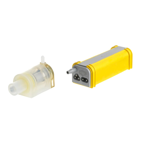
Abdeckung English Instruction manual Combi Product description Combi Kit beinhaltet Diagnostic LED USB port Mitgeliefertes Zubehör Diagnose-LED Stecker Wassersensor Digitaler Sensor DIP-switches USB-Anschluss Pumpenkörper Austauschbarer Filter Water sensor socket Dip-Schalter Werkseitig installierte Sensorgehäuse Pump body Sicherung Factory-installed fuse Digital sensor Stromversorgungskabel Alarmkabel Sensorkabel... - Page 5 Instruction manual Combi English LED alarm relay indications LED alarm relay operation table Start up sequence (normally closed) (normally open) Pump status Condensate level Default operation Peripheral Mode Not powered Powered Below alarm level Powered Alarm-activated ❋ Alarm relay operation is user confi gurable see page 11 ❋ LED indications in operation Pump is miswired or no incoming voltage.
-
Page 6: Transport And Storage
English Instruction manual Combi Factory default Ratings for air conditioning units The rating of the condensate pump has to medium low medium high high be adjusted according to the power of the up to 18K Btu/h up to 42K Btu/h up to 72K Btu/h up to 120K Btu/h conditioning unit. - Page 7 Instruction manual Combi English Horizontal installation Vertical installation Leave silicone plug Remove plug and in water sensor. install vent tube. Horizontal installation...
- Page 8 English Instruction manual Combi Vertical installation...
- Page 9 Instruction manual Combi English...
- Page 10 English Instruction manual Combi Examples are for reference only. WARNING: INPUT POWER: Disconnect all electrical power before starting 100-240V, 50/60Hz, 2.5A (Max) installation, maintenance, or service work. The alarm relay fuse must be rated for the specifi c Installations must only be carried out by application and of the HRC type, 5 x 20mm 250 VAC, qualifi...
- Page 11 Instruction manual Combi English Below are examples of how REFCO pumps can be installed. For reference only. When indoor evaporator unit is powered from the outdoor condenser unit (drawing # 1) Condenser unit (outdoor) Evaporator unit (indoor) Data (communica ons)
- Page 12 English Instruction manual Combi Below are examples of how REFCO pumps can be installed. For reference only. When outdoor condenser is powered from the indoor evaporator unit (drawing # 3) Evaporator (Indoor) Condenser unit (outdoor) Data (communica ons) Earth (ground)
- Page 13 Instruction manual Combi English Power cable must not be entered with a tensile load. Alarm cable and power cable must be completely pressed into the jack. Only use the original power cable and alarm cable...
- Page 14 English Instruction manual Combi Horizontal installation 1/4˝ I.D. (6mm) (Field supplied) to drain...
- Page 15 Instruction manual Combi English Vertical installation 1/4˝I.D. (6mm) (Field supplied)
-
Page 16: Maintenance
English Instruction manual Combi Maintenance Water filter maintenance Regular cleaning / replacement of the Combi water filter will help to prolong the life of the pump. The sole purpose of the water filter is to prevent foreign debris from entering the pump itself. The time period between filter service can only be determined from the specific environment in which the pump is installed. We recommend cleaning or replacing the water filter a minimum of every 12 months. However, when installed in environments with high dust, smoke, cooking oils or the possibility of algae growth it is recommended to clean or replace the filter every 3 months. To clean / replace the water filter, simply remove it from the water sensor body and thoroughly wash with cold water and replace in between the two interior sensor body retaining flanges as shown below. Change alarm fuse Change alarm fuse WARNING: Disconnect all electrical power before starting... -
Page 17: Troubleshooting
Instruction manual Combi English Troubleshooting Fault Correction No LED lights Check for incoming voltage. The blue and brown wires are for power. Pump runs constantly Check filter placement. The water filter should not touch the digital sensor. Check the digital sensor for dirt, mold or debris. Clean with water. Check all tubing connections and ensure they are firmly pressed on the connection barbs and secured using cable ties. Check the entire drain line for clogs, kinks or the tube being pinched. If the pump is running constantly and water is flowing from the end of the drain line then you need to change the dip-switch power settings to increase the pump’s capacity. -
Page 18: Replacement Parts
English Instruction manual Combi Replacement parts and accessories HSG-4065/4 FIL-4063/4 Filter, 4 pcs. Stop-Siphon Device, 4 pcs. Part No 3004063 Part No 3004065 KIT-4087 FUS-4050/10 Star tube with Stop-Siphon device Fuses 5x20 10A, 10 pcs. Part No 3004087 Part No 3004050 PVC-TUBE Plastic tube 6 mm (1⁄4”), minimum 30 meters... - Page 19 Instruction manual Combi English...
- Page 20 REFCO Manufacturing Ltd. Industriestrasse 11 6285 Hitzkirch - Switzerland Telefon +41 41 919 72 82 Telefax +41 41 919 72 83 info@refco.ch www.refco.ch...
Need help?
Do you have a question about the Combi 3004146 and is the answer not in the manual?
Questions and answers