Whelen Engineering Company WPS-4000 Series Operating And Troubleshooting Manual
High power voice & siren system
Hide thumbs
Also See for WPS-4000 Series:
- Procedural manual (2 pages) ,
- Installation manual (33 pages)
Table of Contents
Advertisement
®
ENGINEERING COMPANY INC.
51 Winthrop Road
Chester, Connecticut 06412-0684
Phone: (860) 526-9504
Internet: www.whelen.com
Sales e-mail: Iowsales@whelen.com
Customer Service e-mail: iowserv@whelen.com
WARNING: This product can expose you to chemicals including Methylene Chloride which is known to the State of California to cause cancer, and
Bisphenol A, which is known to the State of California to cause birth defects or other reproductive harm. For more information go to
www.P65Warnings.ca.gov.
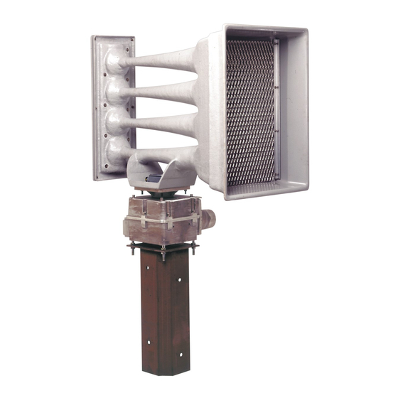
WPS-4000 SERIES
HIGH POWER VOICE
& SIREN SYSTEM
OPERATING AND TROUBLESHOOTING
MANUAL
©2001 Whelen Engineering Company Inc.
For warranty information regarding this product, visit www.whelen.com/warranty
Form No.13575G (050911)
Page 1
Advertisement
Table of Contents

Related Manuals for Whelen Engineering Company WPS-4000 Series


Summary of Contents for Whelen Engineering Company WPS-4000 Series
- Page 1 Bisphenol A, which is known to the State of California to cause birth defects or other reproductive harm. For more information go to www.P65Warnings.ca.gov. WPS-4000 SERIES HIGH POWER VOICE & SIREN SYSTEM OPERATING AND TROUBLESHOOTING MANUAL ©2001 Whelen Engineering Company Inc. For warranty information regarding this product, visit www.whelen.com/warranty Form No.13575G (050911) Page 1...
-
Page 2: Table Of Contents
Table Of Contents Section I: Overview of System Components a) Station Component Locations ................page 4 b) Station Components Defined ................page 6 Section II: System Operations a) Remote Operations .................... page 9 b) Local Operations ....................page 9 Section III: Understanding Station Addressing Central Point Source.................... -
Page 3: Fig. 1: Station Wiring Diagram
Fig. 1: Station Wiring Diagram Page 3... -
Page 4: Overview Of System Components A) Station Component Locations
Section I: Overview of System Components a) Station Component Locations The WPS-4000 High-Power Voice and Siren System is comprised of three basic models: Model Driver Info Cabinet WPS-4000-3 Three, 400 Watt Drivers Type II WPS-4000-4 Four, 400 Watt Drivers Type II WPS-4000-8 Eight, 400 Watt Drivers Type III... -
Page 5: Fig. 3: Wps 4000-8 Siren Cabinet Components
Fig. 3: WPS 4000-8 Siren Cabinet Components LED CODES WPS4000-8 Digital Voice Board Siren Amp 4 Siren Control Board Siren Amp 5 Radio or Landline Board* Siren Amp 6 Control Board Serial Port Siren Amp 7 Amplifier LED Status Board Siren Amp 8 Strobe Control Rotor Relay Module... -
Page 6: B) Station Components Defined
b) Station Components Defined Rotor Control Box - This component (located on the inside of the upper cabinet door) activates the rotor motor after receiving commands from the control board. It also transmits the rotor position to the control board. Connections are as follows: RC1 - Connects the Rotor Control Box to the Control Board RC2 - Connects the Rotor Control Box to the Rotor RC3 - Provides Battery Voltage to the Control Box... - Page 7 Motherboard - This component (located on the inside of the upper cabinet door) distributes Battery Voltage and signals to all system components that require this voltage. The motherboard is fused @5 Amps to protect all connected components EXCEPT for the siren amplifiers and the rotor (they contain their own fuse).
- Page 8 Antenna (optional) - This component (located on the utility pole) is capable of either receiving signals broadcast from the control center (one-way) or can both transmit and receive signals to and from the control center (two-way), depending how the system was ordered.
-
Page 9: System Operations A) Remote Operations
Section II: System Operations a) Remote Operations Remote operation of a WPS-4000 series siren involves transmitting signals from the control center to the desired station. This is accomplished by using either an encoder and transmitter or, if the station is so equipped, using an auxiliary control status board that has been wired to switches/controls at the control center. -
Page 10: Fig. 4: Station Control Panel
Xmit Audio For use with remote station radio transceiver, causes transmission of DTMF tone via RF link for tone modulation adjustment. Xmit Status Transmits station status information and battery voltage to the control center DVM Test Activates the Digital Voice Message (DVM) assigned to the test procedure in the configuration software. -
Page 11: Understanding Station Addressing
Section III: Understanding Station Addressing Every Siren Station in a given area code has its own, unique “Station Address”. This address allows the user to select an individual or a group of stations. As stated elsewhere in this manual, a valid station address can be any number from 0000 to 9999. This allows for 10,000 unique addresses;... - Page 12 In this system, a stations address is structured as follows: Digit Allocation Quadrant (1 to 4) Sector (1 to 4) Radii (1 to 5) Individual station within a radian Here are some sample activations to further illustrate this concept. Sample 1: A station with address 1354 would be located in: Quadrant: Sector:...
- Page 13 Sample 2: If the activation of a group of remote stations within a whole segment of a radius within a quadrant and sector is desired, the fourth digit address is substituted with a “Wild Card”, the “#” pound sign. An address selection of 1 - 3 - 4 - # would activate the system as follows: Quadrant: Sector: 3 of Quadrant 1...
- Page 14 Sample 3: Selection of an entire sector can be accomplished by using the following address: Quadrant: Sector: 3 of Quadrant 1 Radial: # All radial 1 - 3 Station: # All stations defined by above In selecting a sector, the first two digits of the address are set for the sector address, for example 1 - 3 (Quadrant 1 - Sector 3).
- Page 15 Sample 4: The selection of a complete quadrant can be achieved by using the following address: Quadrant: Sector: # All sectors of Quadrant 1 Radial: # All radials in 1 - 3 Station: # All stations defined by above When selecting a quadrant, the first digit designates the Quadrant (1). the second, third and fourth digits are replaced with Wild Cards (#,#,#).
- Page 16 Sample 5: All stations in a system may be accessed by using the Wild Card (#) for all address numbers. The address would be # - # - # - #. Quadrant: # All Quadrants Sector: # All sectors of all Quadrant Radial: # All radials Station:...
-
Page 17: Governmental
Governmental: County, City & Station For this next type of address structure, assume that the siren system in question is used primarily for tornado warnings throughout a major population center. This center encompasses three counties with each county having no more than ten cities. Two cities contain more than 50 high-power voice and siren stations. -
Page 18: Troubleshooting Audio Loss
Section IV: Troubleshooting Audio Loss If after activating the siren there is no audio output, perform the following procedure step by step. This procedure will require a digital multimeter. Locate the Audio Presence LED on the controller board (see “Fig. 6: System LED Diagnostic Indicators”... -
Page 19: Ac Battery Charger
Set your meter to measure DC Volts. Connect the negative lead of your meter to ground (one of the solid black wires in the multi-position connector on the amplifier is a good ground source). With a siren tone activated, measure the following wires for the following voltages (approximately): Wire Proper Voltage... -
Page 20: Solar Regulator
Solar Regulator The following procedure can be performed to confirm proper operation of the solar regulator: Disconnect the solar panel from the charger. With a DC voltmeter, measure the voltage across the wires coming from the solar panel. The voltage should be greater than 32 VDC (NOTE: The solar panel must be in direct sunlight). -
Page 21: Digital Voice
Digital Voice Remove all amplifier fuses. Install an 8 ohm speaker at amplifier audio input connector pins 1 and 2 (Blue and Black w/White wires) in the 16 position connector. Select a siren tone by pressing one of the controls on the front panel. If the tone can be heard through the speaker, press the DVM-Test control to play the predesignated message. -
Page 22: Frequency Of Testing And Activation
Section V: Maintenance Although The WPS-4000 is of a dependable, solid-state design, periodic activation, field inspection and preventive maintenance is recommended to insure the maximum performance of each station. Frequency of Testing and Activation A system of twice-monthly activation and confirmation, combined with a quarterly service and preventive maintenance is recommended to help insure the successful performance of a station. -
Page 23: Quarterly Maintenance
Following activation and observation the results should be noted in the performance log. Any indication of incomplete operation presented by the LED indicators should prompt IMMEDIATE service attention. The SI TEST® system retains information until cleared by a specific command. The SI TEST®... -
Page 24: Visual Siren Station Inspection
Visual Siren Station Physical Inspection • Observe the speaker cluster, siren cabinet and AC Service for any signs of damage or loose mounting hardware (Some shrinkage of a newly treated utility pole may occur in the first several years following installation, requiring the tightening of mounting hardware. -
Page 25: Station Performance Testing
• Verify tightness of all mounting hardware. • Check all wiring terminations and connections. • Verify lubrication of the rotor gear train. The recommended inspection interval is initially 6 months. Following the initial two inspections, the owner may determine if a longer inspection interval is acceptable. - Page 26 SI TEST® Station Analysis - Observe and confirm diagnostic status of: Partial Amplifier & Speaker Driver Operation (disable one amplifier to confirm this test). Full Amplifier & Speaker Driver Operation NOTE: Verify AC drop out during SI TEST® mode. Battery Charger Operation - Observe for proper charging operation.
- Page 27 Rotor - Activate rotor by the “CW” or “CCW” control on the control panel and observe the ammeter. The ammeter should read approximately 3 to 5 amps. A higher reading indicates gear train binding and that lubrication is needed. Exercise the rotor through complete CW rotation. Verify that the rotor stops at limit (360°), requiring the CCW control to be pressed.
-
Page 28: Maintenance Check List
MAINTENANCE CHECK LIST Station #: Siren Address: Installation Date: Inspection Date: Inspector: PHYSICAL INSPECTION: NOT OK COMMENT Mounting Hardware Speaker Assembly AC Service Proper Grounding Solar Panels* Antenna* Conduit Connections Siren Case Assembly Batteries Components Secure Harnesses LOCAL OPERATIONAL TESTING Battery Voltage Manual Test: Clear... - Page 29 MAINTENANCE CHECK LIST (continued) Radio*: NOT OK COMMENT Squelch Control Sensitivity Antenna Tuned* Transmit LED Remote Activation: Clear Wail Attack Alert Public Address Airhorn Hi-Lo Whoop Wail / 5 Sec. North South East West Incremental CW Incremental CCW All Call Speaker LEDs: SI TEST®: Partial...
-
Page 30: Fig. 6: System Led Diagnostic Indicators
Fig. 6: System LED Diagnostic Indicators RADIO 9 POS. "D" RJ45 JACK MIC. JACK REMOTE AUDIO (FOR USE ONLY (FOR USE ONLY WITH MOSCAD) WITH MOSCAD) BATTERIES RS232 / RJ45 PAGING INTERFACE Front Panel Switch Membrane PWR AMPS 1-5 Audio Presence (RED) - Normally off. This Partial - Normally on. -
Page 31: Fig. 7: Control Board Wire Colors
Fig. 7: Control Board Wire Colors RADIO 9 POS. "D" RJ45 JACK MIC. JACK REMOTE AUDIO 1 BLK/WHT BATTERIES 2 RED/WHT NOTE: Some older systems RS232 / RJ45 1 WHT/GRN use connectors that will not 2 WHT/GRN properly interface with the 3 WHT/GRN PAGING 4 WHT/GRN...
Need help?
Do you have a question about the WPS-4000 Series and is the answer not in the manual?
Questions and answers