Table of Contents
Advertisement
Quick Links
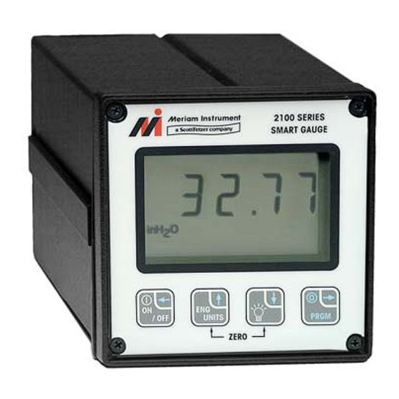
M2110P SMART PRESSURE GAUGE
USER'S MANUAL
Meriam's M2110P Smart Pressure Gauge is a microprocessor-based pressure sensing
device. The various ranges available provide measurement of differential (dry/dry or wet/wet),
gauge, compound or absolute pressure. Three configurations are available: Battery, SetPoint,
and Current Loop models.
All models are programmable through the front keypad. The user's program information is
stored in non-volatile memory and is retained when the power to the gauge is removed.
SetPoint and Current Loop models can also be configured through the RS-232 serial
communication connection.
The Battery models are powered by internal lithium batteries. This model has an LCD for
indication only; it does not support any outputs or RS-232 communications.
SetPoint and Current Loop models have outputs that can be used for control or
indicating/recording functions. Both models also have RS-232 communications capability. In
addition to configuring the gauge, the RS-232 port can be used to monitor and log the
measured pressure data and output status. It can also be used as part of a control system
with digital capabilities.
The SetPoint model provides two SPDT relay outputs with adjustable deadband.
This
configuration provides normally open or normally closed contact operation. Switch SetPoints
can be set from –20% to +120% of the full scale pressure range. The SetPoint model is
powered by 120/240 VAC, or 24VDC.
The Current Loop model provides a 4 to 20 mA output three or four wire pressure transmitter
operation. LRV and URV are set through user-programmable registers from –20% to +120%
of the full scale pressure range. The output is capable of normal and reverse action. The
Current Loop model is powered by 24VDC only.
User's Manual Dwg No. 9R141-IR (1/2011)
Advertisement
Table of Contents

Related Manuals for Meriam M2110P


Summary of Contents for Meriam M2110P
- Page 1 M2110P SMART PRESSURE GAUGE USER’S MANUAL Meriam’s M2110P Smart Pressure Gauge is a microprocessor-based pressure sensing device. The various ranges available provide measurement of differential (dry/dry or wet/wet), gauge, compound or absolute pressure. Three configurations are available: Battery, SetPoint, and Current Loop models.
-
Page 2: Safety Information
In no event shall Meriam be liable for any indirect, special, incidental, consequential or punitive damages or for any lost profits arising out of or relating to any services provided by Meriam or its affiliates. It is not possible for Meriam to identify all foreseeable uses/misuses, therefore all persons involved in commissioning, using or maintaining this product must satisfy themselves that each intended application is acceptable. -
Page 3: Table Of Contents
Table of Contents Certification / Safety / Warnings..............4 Pressure Display....................5 Keypad Functions ..................6 Programmable Register Overview ..............8 Engineering Units ..................9 Zero Reference....................10 P0 – Lockout Code All Models..............11 P1 – Time Out Value Battery Models Only ..........12 P2 – Damp Rate All Models...............13 10. -
Page 4: Certification / Safety / Warnings
1. Certification / Safety / Warnings Fire/Explosion Hazard. This instrument is not intrinsically safe. DO NOT use or service in areas that may contain flammable gas or vapors, combustible dusts or ignitable fibers where an unintended spark can cause a fire/explosion. Do not exceed the Pressure Limits listed in the Product Specifications section of this manual. -
Page 5: Pressure Display
Absolute Isolated sensor is used. Performance The M2110P Smart Gauge retrieves analog data from its pressure sensor, and performs an analog-to- digital (A/D) conversion for microprocessor-based data handling. The rate of A/D conversion will typically be between 10 to 14 conversions per second, depending on the various operating conditions. -
Page 6: Keypad Functions
3. Keypad Functions The keys on the front panel perform multiple functions. Their function differs depending on whether the gauge is in Measure Mode or Program Mode. • Measure Mode is the normal operating mode for measuring and displaying pressure. This mode is always default after power-up or reset. - Page 7 Backlight/Do Document Symbol: (Down↓) wn Arrow Key Toggles the display Backlight on and off. Note that the default Backlight status for the Measure Mode Battery model is OFF to conserve battery life. The other models will retain the prior Backlight status as default. Scroll down function.
-
Page 8: Programmable Register Overview
4. Programmable Register Overview All M2110P Smart Pressure Gauges have programmable registers that allow the gauge to be configured to fit the pressure measurement application. Programmable registers are numbered P0 through P8. Each register controls a specific aspect of the gauge’s performance. -
Page 9: Engineering Units
5. Engineering Units The following Engineering Units are available on the M2110P: – Inches of Water Column (ref. temp. selections: 20°C, 4°C, 60°F) 2. PSI – Pounds per Square Inch 3. Kg/cm – Kilograms per Centimeter squared 4. kPa – KiloPascals 5. -
Page 10: Zero Reference
This is the value set during calibration of the sensor, and is typically 0.0. RANGE CHECK The M2110P can be zeroed only when the applied pressure is within ±5% of full scale. If the applied pressure is greater than 5% of full scale, an error code will be displayed when zeroing is attempted. -
Page 11: P0 - Lockout Code All Models
7. P0 – Lockout Code All Models This feature provides security in the M2110P. It is designed to prevent unauthorized personnel from tampering with or inadvertently changing the configuration of the gauge. The lockout is controlled by a 2-digit setting in the P0 register. -
Page 12: P1 - Time Out Value Battery Models Only
The Zero function (Up↑ and Down↓) will reset the entire register to 00 and allow editing to continue. The next digit begins flashing for edit. Press the PRGM/Enter→ key to accept the digit. Repeat steps 4 and 5 for the second digit. The complete 2-digit value will be accepted, and the register is closed (display shows P0 for selection). -
Page 13: P2 - Damp Rate All Models
9. P2 – Damp Rate All Models The M2110P has a selectable damp rate, which is used to stabilize the display for applications with a pulsating pressure source. The damp rate setting is roughly the length of time it will take for the gauge to ramp from one stable pressure to another. -
Page 14: P3 - Density Of Water Reference Temperature All Models
10. P3 – Density of Water Reference Temperature All Models The M2110P supports pressure units of inches of water column and centimeters of water column, at three different water temperature references: 20°C, 4°F and 60°F. The base reference temperature is 20°C on all gauges. -
Page 15: P4 - User Scale All Models
STEP BY STEP: P3, DENSITY OF WATER REFERENCE TEMP Step Action Display Gauge should be in the normal Measure Mode. Normal Pressure Display. The PRGM annunciator shows at the top of the Press the PRGM/Enter→ key. display, and the display shows the register name If the lockout is active, the gauge will now prompt for entry of “P0”. - Page 16 QUICK REFERENCE: P4, USER SCALE Name Description Value Range Notes User Units Enables gauge to display units 0 to 9,999 (Keypad) User defined Full Scale other than factory defined value. 0 to 19,999 (Serial) Engineering Units. STEP BY STEP: P4, USER SCALE Step Action Display...
-
Page 17: P5 - Setpoint Options Set Point & Current Loop Models Only
STEP BY STEP: P4, USER SCALE Step Action Display Notes 1. Preceding/Trailing zeroes are determined by where the user places the decimal point. When opening a register, the value is always shown padded with trailing zeroes. 2. Only 4 digits are available for editing (the ½ digit is not provided), plus the decimal point and negative sign (negative is not applicable to register P4). - Page 18 STEP BY STEP: P5, SETPOINT OPTIONS Step Action Display Gauge should be in the normal Measure Mode. Normal Pressure Display. The PRGM annunciator shows at the top of the Press the PRGM/Enter→ key. display, and the display shows the register name If the lockout is active, the gauge will now prompt for entry of “P0”.
-
Page 19: P6 & P7 - Setpoint (Set1 & Set2)
13. P6 & P7 – SETPOINT (Set1 & Set2) SetPoint Model These registers define the pressure points at which the SPDT relays will energize. The relay will energize when the pressure exceeds its corresponding value, and de-energize when the pressure drops below the value (minus deadband;... - Page 20 QUICK REFERENCE: P6/P7, SETPOINTS Name Description Value Range Notes SET1 SetPoint model: –20% to +120% User defined Controls SET1 relay. of Full Scale values. Current Loop model: On Current Sets 4.00 mA value. Loop models, SET1 cannot SET2 SetPoint model: –20% to +120% equal SET2.
-
Page 21: P8 - Deadband Set Point Models Only
Decimal point moves accordingly. Press the Up↑ or Down↓ keys repeatedly to scroll to the desired decimal point position, and to select Please read carefully note 4 on page 17. positive/negative. Negative Sign activates and de-activates when the decimal point sequence is scrolled through If the Zero function (Up↑... -
Page 22: Lockout Code Prompt
All available choices are scrolled. Press the Up↑ or Down↓ keys repeatedly to scroll to the desired register value. (Choices indicate actual Deadband in percent of full scale.) The Zero function (Up↑ and Down↓) will reset the scroll to default and allow editing to continue. The value is accepted, and the register is closed. -
Page 23: Serial Port Service
Measure Mode unchanged. 16. Serial Port Service The M2110P Smart Gauge SetPoint models and Current Loop models provide RS-232C communication capability. To use the serial service, connect a standard “dumb terminal” (or personal computer with terminal software) as shown in the wiring diagram. - Page 24 SmartGauge/2110P (v5.00). (c)Copyright 2010 Meriam Instrument. SetPoint model. Sensor = 200.0 inH2O; ---------------------------------------------------------------- Notice! Changing any value will PAUSE Gauge Operation, which will also pause updates to the outputs and display. ---------------------------------------------------------------- Current Full Scale: 200.0 inH2O @ 20 Deg C.
- Page 25 The Notice of “PAUSE Gauge Operation” near the top of the menu is a reminder about this explanation. It is particularly important when a gauge is in service as an in-process instrument, since the gauge will not respond to process conditions while it is paused. TIMEOUT When the menu is displayed, it has no impact on gauge operation or performance.
-
Page 26: Error Codes
17. Error Codes All model M2110P gauges have an error/message feature to inform the operator of problems with the operation or programming of the gauge. These Error Codes and messages are identified and described in the table below. ERROR DESCRIPTION “OP”... -
Page 27: Installation & Wiring
18. Installation & Wiring Differential pressure sensors have two pressure connections on the back of the gauge. The diagram at the left shows the correct connections to obtain the desired type of pressure measurement. Gauge-Isolated and Absolute-Isolated pressure gauges have only one pressure connection. - Page 28 Note: The Smart Gauge comes with 1/8” FNPT pressure port(s). Gauge and Absolute models only use one pressure port. The unused port vents the enclosure/sensor to atmosphere. DO NOT REMOVE THE SINTERED PLUG (ALLEN HEAD FITTING). The Smart Gauge should be panel-mounted or held firmly in one hand while a small wrench is used to tighten the 1/8”...
-
Page 29: Outline Dimensions
19. Outline Dimensions 20. Panel Mounting 20. Panel Mounting PANEL MOUNTING CUTOUT DIMENSIONS 1. Make a ¼ DIN panel cutout per drawing. 2. Remove the two 6-32 socket head screws in the grooves at the rear of the gauge. 3. Slide the panel mount jacks out of the groove. -
Page 30: Product Specifications
21. Product Specifications TYPE & RANGE: DISPLAY: 4 1/2 digit, 0.6 inch (15.24 mm) LCD. DN: Differential Non-Isolated PRESSURE CONNECTIONS: 1/8" female NPT. CI: Compound Isolated Brass on non-isolated, 316SS on isolated sensors. GI: Gauge Isolated AI: Absolute Isolated INPUT POWER: SetPoint model is standard with DI: Wet/Wet Differential Isolated selectable 110V AC 50/60 Hz, 240V AC 50/60 Hz, or 24V DC power. -
Page 31: Range Limits And Indication
22. Range Limits and Indication Sensor Hard Soft Certified Soft Hard Type Under Under Range Over Over Range Range (F.S.) Range Range Under -20 to 0% 0 to 100% 100 to Over -20% 120% 120% Under -20 to 0% 0 to 100% 100 to Over -20%... -
Page 32: Service And Calibration
The battery board should only be replaced by properly trained technicians in a controlled environment. Contact Meriam for further details. DO NOT send any unit in for service without first contacting Meriam for a Return Material Authorization (RMA) number. If this number has not been obtained and clearly marked on the return packaging, the unit will be returned at the shipper’s...
Need help?
Do you have a question about the M2110P and is the answer not in the manual?
Questions and answers