Table of Contents
Advertisement
Quick Links
10920 Madison Ave.
Cleveland Ohio 44102 USA
+ 1 216 281 1100
Meriam.com
(800) 817-7849
A trusted leader in measurement
and calibration solutions.
First things first
General purpose use only
M2004 Smart Manometer
DANGER
!
MST Sensors
These are not intended for hazardous locations.
Steps to get started
Make a connection
▪
Attach the pressure fittings to the
internal
pressure sensor module.
▫
The threads should be coated with a pipe
sealant compound before installation.
▫
Tighten to finger tight plus 1.5 turns to 3
turns using a 19 mm (3/4 in.) wrench on the
manifold.
Use only a
wrench
on the fitting
NOTICE
and the manifold.
▪
Optional:
Attach the pressure fittings to the
external pressure sensor module.
▪
Optional:
Attach the RTD cable and probe to an
RTD module.
Carefully equalize the pressure
To avoid damaging
differential sensors:
1.
Make sure you are connecting to the correct
pressure port on DN or DI differential pressure
modules.
1.
P1 port is high pressure.
2.
P2 port is low pressure.
2.
Apply pressure to both differential ports (P1 and
P2) at the same time.
9R711-A
Know your batteries
The Smart Manometer is powered by four 1.5 volt
AA size batteries.
mix batteries—not by manufacturer or by
▪
Never
size, by capacity, or by chemistry.
mix old and new batteries.
▪
Never
▪
Remove
all four batteries in the Smart
Manometer at the same time.
▪
Replace
all four batteries with batteries from the
same package or with the same expiration date.
Install the batteries
1.
Turn over the Smart Manometer so the display
faces down.
2.
Remove the two screws on the battery cover
with the Phillips head screwdriver by turning
them counterclockwise.
3.
Insert four AA batteries.
Pay attention to the positive (+) and
Note:
negative (−) battery polarity markings at the
bottom of the compartment.
4.
Replace the battery cover. To secure the cover,
torque the screws clockwise 2 in. lbs. maximum.
M2004 Smart Manometer & Sensors
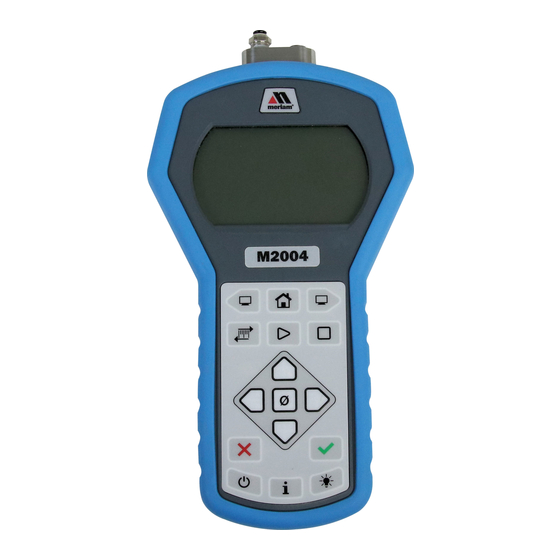
Learn the function keys
Meriam Tethered Sensors (MTS)
Optional Meriam Tethered Sensors
Pressure (Absolute, Compound, Differential).
▪
▪
Temperature (RTD PT100).
Make an electrical connection
▪
Align the red dot on the Smart Manometer with
the red dot on the Tether cable and push in.
▪
Align the red dot on the MTS with the red dot
on the Tether cable and push in.
© Meriam 2018
USB cable & meriSuite CG
The keys from
left to right
For use only in non-hazardous locations
1.
Backward
2.
Home
WARNING
!
3.
Forward
4.
Units
Connect the USB cable to the Smart Manometer
5.
Start
and to your computer to configure it and the
6.
Stop
sensors using the meriSuite CG application.
7.
Up arrow
Install USB Drivers & meriSuite CG
8.
Left arrow
9.
Zero or Tare
You must install USB Drivers first then install the
10. Right arrow
meriSuite CG application.
11. Down arrow
12. Cancel or Esc
For installation instructions:
×
or
https://www.meriam.com/resources/download/
13. Accept or ✓
Open meriSuite CG
14. Power
15. Information
Use meriSuite CG application to:
16. Backlight
▪
Sync PC Time to Gauge
display.
Select or deselect the Display functions on
▪
each Smart Manometer or Measurement Units
that you need on each sensor.
▪
Select the timeout for the Backlight and for the
Auto Off.
Close meriSuite CG
NOTICE
▪
Do not turn off the power on the M2004 while it
is communicating with meriSuite CG.
Close meriSuite CG first, disconnect the USB,
▪
and turn off the Smart Manometer.
Quick Start Guide
for data logging and
Page 1 of 2
Advertisement
Table of Contents

Related Manuals for Meriam M2004


Summary of Contents for Meriam M2004
- Page 1 P1 port is high pressure. the red dot on the Tether cable and push in. ▪ Do not turn off the power on the M2004 while it P2 port is low pressure. ▪ Align the red dot on the MTS with the red dot is communicating with meriSuite CG.
-
Page 2: Frequently Asked Questions
15 psi and 3 000 psi sensor? outline of the icon flashes. If a given measurement unit cannot display the correct number of digits, the Smart Manometer automatically advances to the next displayable unit. 9R711-A © Meriam 2018 Page 2 of 2...
Need help?
Do you have a question about the M2004 and is the answer not in the manual?
Questions and answers