Table of Contents
Advertisement
Quick Links
Advertisement
Table of Contents

Related Manuals for Meriam M2000


Summary of Contents for Meriam M2000
-
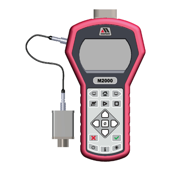
Page 1: M2000 Smart Manometer
Cleveland | Ohio | 44102 | USA + 1 216 281 1100 Meriam.com (800) 817-7849 A trusted leader in measurement and calibration solutions. M2000 Smart Manometer Smart Manometers and Sensors Meriam Tethered Sensors meriSuite CG Application Copyright © 2018 Meriam®... -
Page 2: Table Of Contents
CG and USB Drivers required ............30 Tips for using meriSuite CG ..................31 Connection status......................34 Configuration button ......................36 User Calibration button ....................40 Data Log button .........................42 TSV file format ........................44 Application button ......................55 Update button ........................56 User Manual for M2000 Smart Manometer 2 of 68... - Page 3 ........................65 Cleaning ...........................65 Prepare the Smart Manometer for storage ............65 Help ..................................66 Register your product ....................66 Find downloads and documents ................66 Returning for repair or calibration ................67 Meriam Contact Information ......................68 User Manual for M2000 Smart Manometer 3 of 68...
-
Page 4: General Information
Meriam or its affiliates. It is not possible for Meriam to identify all foreseeable uses or misuses, therefore all persons involved in commissioning, using, or maintaining this product must satisfy their self that each intended application is acceptable. -
Page 5: Glossary
MTS RTD temperature sensor. • Data from the internal and external pressure p1. P 2 sensors display in two lines on the Smart Manometer at the same time. User Manual for M2000 Smart Manometer 5 of 68... - Page 6 The displayed result of the internal pressure Diff p2-p1 measurement subtracted from the external pressure measurement. • displays on the process readout --out- --out- when the information readout is providing information about exiting tests. User Manual for M2000 Smart Manometer 6 of 68...
-
Page 7: General Warnings And Cautions
Indicates a potentially hazardous situation CAUTION which, if not avoided, could result in minor or moderate injury. Indicates information essential for NOTICE proper product installation, operation or maintenance. User Manual for M2000 Smart Manometer 7 of 68... -
Page 8: Sample Label For General Purpose Smart Manometers
October 2018 Sample label for General Purpose Smart Manometers All M2000 Series models are available for general-purpose use. General Purpose (GP) versions are identified by the name plate located on the rear of the unit under the protective rubber boot. A... -
Page 9: Do Not Exceed Pressure Limits
▪ Do not exceed the Pressure Limits listed in the Specifications section of this manual. Failure to operate within the specified pressure limit could ▪ result in minor or moderate injury. User Manual for M2000 Smart Manometer 9 of 68... -
Page 10: Sensors
Apply pressure to both differential ports at the same time. Note: See Overrange limit in the section called Specifications concerning overrange pressure limits. If over pressure damage occurs, you must return the Smart Manometer to the factory for sensor replacement. User Manual for M2000 Smart Manometer 10 of 68... - Page 11 9R715-IR October 2018 Sensor manifold types ZMTS-CNXXXX ZMTS-CIXXXX ZM2000-CNXXXX ZM2000-CIXXXX ZMTS-DNXXXX ZMTS-DIXXXX ZM2000-DNXXXX ZM2000-DIXXXX ZMTS-ANXXXX ZMTS-AIXXXX ZM2000-ANXXXX ZM2000-AIXXXX ZMTS-RTD User Manual for M2000 Smart Manometer 11 of 68...
-
Page 12: Meriam Tethered Sensors (Mts)
Note: This feature is intended for comparison purposes, and should not be used for real pressure measurement. This feature does not compensate for any zero drift. User Manual for M2000 Smart Manometer 12 of 68... - Page 13 Accept key when you see these characters appear. • This refers to User Defined Offset (Zero). You u5Er 0 can set an absolute reference point other than zero. User Manual for M2000 Smart Manometer 13 of 68...
-
Page 14: How To Zero Dn, Di, Or Ci Sensors
Factory service may be required. 5. You can turn off the Zero function in meriSuite CG Allow zero adjust (Ø) deselecting in the Display Functions list. User Manual for M2000 Smart Manometer 14 of 68... -
Page 15: Smart Manometer
• Duracell MN1500 • Panasonic LR6XWA • Duracell PC1500 • Rayovac 815 • Energizer EN91 • Varta 4906 Note: The Smart Manometer is powered by four 1.5 volt AA size batteries. User Manual for M2000 Smart Manometer 15 of 68... - Page 16 6. Do not over tighten. NOTICE To prevent internal damage to circuitry, do not substitute screws with lengths that are different from the screws Meriam provided to you. Watch for the low battery indicator The battery indicator on the display shows the current charge.
-
Page 17: The Display
12. LEAK TEST DURATION Display function NOT appearing on the MTS The following display function do not appear on an MTS when you attach it to the Smart Manometer. ▪ Temperature & Time. User Manual for M2000 Smart Manometer 17 of 68... -
Page 18: Keypad: Description Of The Keys
Turns the Smart Manometer on or off. Information • Displays information about the Smart Manometer, internal sensor, attached MTS sensor, and the firmware. Backlight • It provides three levels of brightness and off. User Manual for M2000 Smart Manometer 18 of 68... - Page 19 SNSR NAME [this message scrolls to display the information]. DEV F/W VER DEV is an abbreviation for device; it refers to the M2000 (this message scrolls to display the information). DEV S/N (this message scrolls to display the information). DEV NAME refers to the Smart Manometer (this message scrolls to display the information).
-
Page 20: The Backlight
Pressure has exceeded the calibrated accuracy of the Smart ▪ Manometer. ▪ Pressure has fallen below the stated accuracy of the M2000. Note: The red backlight overrides the white backlight. Overrange condition During an error or overrange condition, the red backlight overrides the white backlight. -
Page 21: Measurement Units
Standard Measurement Units (non-custom) CMW4C KG/M2 INW20C CMW60F INW4C MW2OC INW60F MW4C FTW2OC MW60F FTW4C INHG0C FTW60F MGH0C MBAR MMW20C CMGH0C MMW4C MMHG0C OZ/IN2 MMW60F TORR LB/FT2 KG/CM2 CMW2OC User Manual for M2000 Smart Manometer 21 of 68... -
Page 22: Damping
▪ display when you measure pulsating pressure or flow. Exponential damping displays approximately 70 % of a step ▪ change in pressure at the next display update. User Manual for M2000 Smart Manometer 22 of 68... -
Page 23: Data Logging
Data Log Pro log. Information 4. While is running, you may press the DATA LOG key to see how much time is remaining for the active log. User Manual for M2000 Smart Manometer 23 of 68... -
Page 24: Leak Test
X Cancels Zero to start over (the “0” key). 0 Clears After reviewing or changing these settings, press the Backward key to go to the screen to start the Leak Test. User Manual for M2000 Smart Manometer 24 of 68... - Page 25 Data Log requires pressing and holding the Start key until you Starting. Start see the word In a Leak Test press and release the key (the on-screen message refers to this action as TAP). User Manual for M2000 Smart Manometer 25 of 68...
- Page 26 Exit the test during the count down to zero Press the Cancel key or the Accept key to exit the test. 2. Press the Home key to return to the Home screen. User Manual for M2000 Smart Manometer 26 of 68...
-
Page 27: Relief Valve Test
Press the Zero key and appears and new values HOLD.OFF continue to display. 5. Press the Forward key to see value. MAX TEST P User Manual for M2000 Smart Manometer 27 of 68... -
Page 28: Differential Displays
How long will the Smart Manometer remain on if I leave it unattended? ▪ The default setting is Always You can configure the timeout for the Auto Off with ▪ meriSuite CG. User Manual for M2000 Smart Manometer 28 of 68... -
Page 29: What Does The Zero (Ø) Key Do
Holding the Zero key The key must be held to perform the Zero or Tare mode. The displayed value(s) dashes out during the zero or tare process. User Manual for M2000 Smart Manometer 29 of 68... -
Page 30: Merisuite Cg Application
October 2018 meriSuite CG application How does meriSuite CG benefit you? Note: meriSuite CG is not required to operate the M2000. You can configure your Smart Manometer or sensor to display ▪ information the way your company needs to use it. -
Page 31: Tips For Using Merisuite Cg
Smart Manometer or sensor. Close meriSuite CG first, disconnect the USB, and turn off your ▪ Smart Manometer. ▪ As long as remains visible, Auto Off is USB ACTIVE suspended. User Manual for M2000 Smart Manometer 31 of 68... - Page 32 See Figure 1 and Figure 2 below. You may click the Write button to save the changes you made. ▪ Figure 1: Yellow dot on an active tab. See the red circle in the figure below. User Manual for M2000 Smart Manometer 32 of 68...
- Page 33 US - Arizona -7:00 US - Eastern -5:00 US - Pacific-8:00 US - Central -6:00 US - Alaska -9:00 US - Mountain -7:00 US - Hawaii -10:00 For example: 15:05:45 UTC (hours:minutes:seconds). ▪ User Manual for M2000 Smart Manometer 33 of 68...
-
Page 34: Connection Status
9R715-IR October 2018 Connection status Attached devices The meriSuite CG application displays the figures of the Smart Manometer and tethered sensor. Descriptions appear alongside both of them. See the figure below. User Manual for M2000 Smart Manometer 34 of 68... - Page 35 The meriSuite CG application displays no figure of devices on the right side. See the figure below. No tethered sensor attached Notice the figure of the Smart Manometer and description. See the figure below. User Manual for M2000 Smart Manometer 35 of 68...
-
Page 36: Configuration Button
An internal sensor and a tethered sensor have their own separate passwords. Each device can have its password turned on or turned off ▪ independently from any other tethered sensor. meriSuite CG retrieves the passwords stored on the devices. ▪ User Manual for M2000 Smart Manometer 36 of 68... - Page 37 You must have the serial number of the device or sensor to ▪ request a recovery password. Call + 1 216 281 1100 or send an e-mail to sales@meriam.com. ▪ Recovery password valid for one date When you call Meriam to generate a recovery password, you may select a date that is convenient for you.
- Page 38 Min/Max. ▪ Accuracy. ▪ ▪ Tare. Average. ▪ Rate of Change. ▪ ▪ Relief Valve Test. Time & Temp. ▪ Data Log. ▪ ▪ Allow zero adjust (Ø) Leak Test. ▪ User Manual for M2000 Smart Manometer 38 of 68...
- Page 39 Exponential damping displays approximately 70 % of a step ▪ change in pressure at the next display update. User Manual for M2000 Smart Manometer 39 of 68...
-
Page 40: User Calibration Button
3. Apply reference pressure within the range shown. 4. Enter the reference value. 5. Save the point. 6. Repeat steps 2-5 until you are done. (You have to change at least one point.) Click the Apply button. User Manual for M2000 Smart Manometer 40 of 68... - Page 41 Calibration Procedure. It is intended to correct the curve fit if the actual sensor characteristics change slightly over time. For sensors up to 200 psi, Meriam recommends a ± 0.0015 % of reading deadweight tester. For sensors 200 psi and above, a ±...
-
Page 42: Data Log Button
CG. Data Log Pro alert The button displays a yellow alert icon to indicate you have changed a setting and you have not yet saved the setting to the Smart Manometer. User Manual for M2000 Smart Manometer 42 of 68... - Page 43 The pressure indicates the reading at each 15-second interval in the data set. The Temperature The MTS displays when it is attached (pressure or ▪ temperature). Temperature displays only when the MTS RTD is attached. ▪ User Manual for M2000 Smart Manometer 43 of 68...
-
Page 44: Tsv File Format
TSV file. 4. Select the file and drag-and-drop it in the middle of the blank spreadsheet. Excel 5. Save it as an file. User Manual for M2000 Smart Manometer 44 of 68... - Page 45 Note: Other spreadsheet applications offer similar features. In the figure below, the file would print on at least four pages. User Manual for M2000 Smart Manometer 45 of 68...
- Page 46 Enter Activation Key edit box and an Activate Device button to replace Lite with Pro. Note: The Activate Pro button remains unavailable until you enter an activation key number. User Manual for M2000 Smart Manometer 46 of 68...
- Page 47 Do I need a license for each sensor? ▪ Data Logging NOTICE The Auto Off (automatic shutoff) timeout is suspended for ▪ Data Logging sessions. ▪ Make sure to end the session to restart the Auto Off timeout. User Manual for M2000 Smart Manometer 47 of 68...
- Page 48 CG dashboard when the device is connected. Add it later You may add Data Log Pro at any time by calling your distributor or by contacting the Meriam Sales Team. You must have the serial number from the Smart Manometer.
- Page 49 Smart Manometer. Two ways to open a log: Double click a log to open it in the Preview tab. ▪ Preview ▪ Or, you may select a log from the list and click the to view it. User Manual for M2000 Smart Manometer 49 of 68...
- Page 50 Preview opens. The Preview tab contains seven areas of information: Data Log Information list. 2. Sensor Information list. 3. Notes. 4. Legend. 5. Samples table. 6. Navigation bar. Save button. User Manual for M2000 Smart Manometer 50 of 68...
- Page 51 Smart Manometer recorded this particular log. 3. Notes ▪ Any information that displays here comes from the text you enter in the Notes box in the Data Log Pro Setup tab. User Manual for M2000 Smart Manometer 51 of 68...
- Page 52 Smart Manometer that you are currently viewing. 7. Save button Click the Save button on the right side and the Save As appears. You can save the file in two file formats: PDF. ▪ ▪ TSV. User Manual for M2000 Smart Manometer 52 of 68...
- Page 53 Interval. Notes edit box Notes you enter in this edit box appear in the Preview tab, the TSV file, and the PDF file. This field is limited to 64 characters. User Manual for M2000 Smart Manometer 53 of 68...
- Page 54 Manometer and overwrites the parameters stored on the Smart Manometer. Note: If a sensor has a password, then clicking this button requires you to enter a password. This password was created in Configuration tab. User Manual for M2000 Smart Manometer 54 of 68...
-
Page 55: Application Button
It displays a red alert icon with an “x” to indicate” “There is no connection to the update server. This is usually caused by the PC not having internet connectivity or the server may be temporarily unavailable. ” User Manual for M2000 Smart Manometer 55 of 68... -
Page 56: Update Button
It displays a to indicate: “There is no connection to the update server. This is usually caused by the PC not having internet connectivity or the server may be temporarily unavailable. ” User Manual for M2000 Smart Manometer 56 of 68... -
Page 57: Specifications
15 psi ZM2000-DI0030 -14.5 psi to 30 psi ZM2000-DI0050 -14.5 psi to 50 psi ZM2000-DI0100 -14.5 psi to 100 psi ZM2000-DI0300 -14.5 psi to 300 psi ZM2000-DI0500 -14.5 psi to 500 psi User Manual for M2000 Smart Manometer 57 of 68... -
Page 58: Internal Sensors: Type And Range - Continued
1 psi ZM2000-DN0005 -5 psi to 5 psi ZM2000-DN0015 -14.5 psi to 15 psi ZM2000-DN0030 -14.5 psi to 30 psi ZM2000-DN0050 -14.5 psi to 50 psi ZM2000-DN0100 -14.5 psi to 100 psi User Manual for M2000 Smart Manometer 58 of 68... -
Page 59: Meriam Tethered Sensors: Type And Range
-5 psi 5 psi ZMTS-DN0015 –14.5 psi 15 psi ZMTS-DN0030 –14.5 psi 30 psi ZMTS-DN0050 –14.5 psi 50 psi ZMTS-DN0100 –14.5 psi 100 psi RTD Temperature sensor ZMTS-RTD -50 °C 250 °C User Manual for M2000 Smart Manometer 59 of 68... - Page 60 Alternate sensor options available ▫ Temperature Measurement Typical Accuracy Specification ▪ ± 0.3 °C total error band from -20 °C to 50 °C ▫ End to end probe inclusive ▫ ▫ Alternate specifications available User Manual for M2000 Smart Manometer 60 of 68...
-
Page 61: Overrange Limit
▪ IP52 for the M2000 IP54 for the MTS ▪ Altitude specifications NOTICE Do not use the M2000 Smart Manometer at an altitude above 2000 m (6561 ft.). Keypad ▪ Sealed membrane 16 domes. User Manual for M2000 Smart Manometer... -
Page 62: Media Compatibility
(LO) only is 3x range or 150 PSI, whichever is less. DN, CN, and AN units: ▪ 3x range or 200 psi, whichever is less. Battery Type 4 AA alkaline batteries of the same battery type. User Manual for M2000 Smart Manometer 62 of 68... -
Page 63: Dimensional Specifications
9R715-IR October 2018 Dimensional specifications User Manual for M2000 Smart Manometer 63 of 68... -
Page 64: Weight
1000 g (35.2 oz. or 2.2 lb.) ▪ MTS pressure module 148 g or 0.33 lb. ▪ ▪ MTS temperature module 92.5 g or 0.20 lb. Enclosure Polycarbonate / ABS alloy. User Manual for M2000 Smart Manometer 64 of 68... -
Page 65: Maintenance And Cleaning
Follow the battery manufacturer’s instructions for storing your batteries. Store the Smart Manometer The recommended storage temperature for the Smart ▪ Manometer is between: –20 °C to 70 °C (–4 °F to 158 °F) User Manual for M2000 Smart Manometer 65 of 68... -
Page 66: Help
User Manuals and Quick Start Guides Downloads | Applications (software), firmware, updates, installation instructions Certifications | Certifications and approvals SDS (MSDS) | Safety Data Sheets Control Drawings | Intrinsically Safe Drawings User Manual for M2000 Smart Manometer 66 of 68... -
Page 67: Returning For Repair Or Calibration
First ― Request a number In the event that a device requires service and must be returned, please contact Meriam using one of the methods listed in the following table to request a Return Material Authorization (RMA) number. -
Page 68: Meriam Contact Information
Return Material Authorization & Service & Repair Department returnforms@meriam.com Sales Department ▪ sales@meriam.com Website meriam.com Find a local Meriam representative Use this map to help you find a Meriam representative. ▪ http://www.meriam.com/representatives-map/ User Manual for M2000 Smart Manometer 68 of 68...
Need help?
Do you have a question about the M2000 and is the answer not in the manual?
Questions and answers