Table of Contents
Advertisement
Quick Links
Operation Manual
Dip Simulator
DSI1020
DSI3020
1020
POWER
Part No. IB028174
Jun. 2015
POWER
Options 3
Advertisement
Table of Contents

Related Manuals for Kikusui DSI1020


Summary of Contents for Kikusui DSI1020
-
Page 1: Table Of Contents
Voltage dips, short interruptions and voltage variations immunity tests 10 Dip Simulator Installing the Test System 12 Product’s component names and functions 12 DSI1020 Test system installation procedure 16 Connecting the sync signal interface 18 DSI3020 Connecting the test circuit 20... -
Page 2: Notations Used In This Manual
For details on how to use the product, see the operation manual for the application software. • In this manual, DSI1020/DSI3020 Dip Simulator is also For details on how to handle hardware including Kikusui AC referred to as “the product,” “this product,” or “DSI.”... -
Page 3: Checking The Package Contents
If something is damaged or missing, USB interface (factory option) contact your Kikusui agent or distributor. We recommend that you save all packing materials, in case A communication interface unit for controlling the product the product needs to be transported at a later date. -
Page 4: Safety Markings
• Do not disassemble or modify the product. If you Chassis (frame) terminal. need to modify the product, contact your Kikusui agent or distributor. On (power supply). Maintenance, Inspection and Calibration Off (power supply). -
Page 5: Precautions When Choosing The Installation Location
• Affix the heavy object warning label. Affix the heavy object warning label to the product where it can be readily seen. The DSI1020 weights approximately 110 kg (243 lbs). The DSI3020 weighs approximately 4-M5 Pass the screws through the top screw holes. -
Page 6: Precautions For Moving The Product
(There are four eye bolt holes on the top panel of this product. M10 eye bolts can be used for the DSI1020, and M12 eye bolts can be used for the DSI3020.) When you move the product, do not tip the product on its side or turn it upside down. -
Page 7: Introduction
This is an option unit used to construct a test system complying with the “Voltage Dips, Short Interruptions and Voltage Variations Immunity Tests” as defined in the IEC61000-4-11 (2004) standard. It can be used in combination with one or more Kikusui AC power supplies (PCR- LE and PCR-LE2 series). -
Page 8: Product Features
400 V line-voltage systems. Incorporation into a total test system By combining this product with a Kikusui Harmonic/Flicker Analyzer (KHA series) and a line impedance network (LIN series), you can construct a total test system that fully com- plies with relevant IEC standards. - Page 9 OUTPUT SOURCE LOAD AUX(SLOT3) SENSING SENSING ± SENSING ± SENSING ± PCR CONTROL Connect to PCR-LE, LIN3020JF, DSI3020, DSI3020 KHA3000 INPUT OUTPUT (SD009-PCR-LE) Oscilloscope PHASE IN TRIG IN TRIG OUT Example of a three-phase four-wire total test system DSI1020/ DSI3020...
-
Page 10: Overview Of The Test System
Kikusui AC power supplies. Be sure to use this product in combination with one or more Kikusui PCR-LE or PCR-LE2 series AC power supplies. It cannot be combined with AC power supplies made by other manufacturers. - Page 11 Sync signal interface Install the control board supplied with this product in SLOT3 of the (master) AC power supply. Application software for controlling the test system Use the SD009-PCR-LE Quick Immunity Sequencer 2 application software to control the test system. DSI1020/ DSI3020...
-
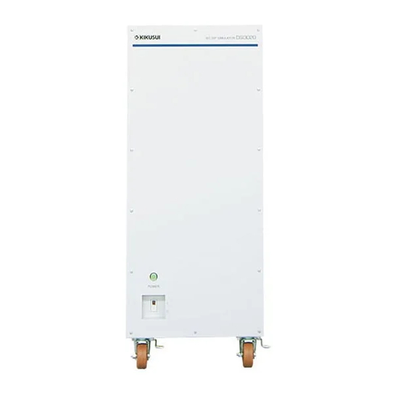
Page 12: Installing The Test System
First, the product’s component names and functions will be described. For details on the component names and functions of AC power supplies, see the AC power supply manual. Product’s component names and functions Model DSI1020 front panel 1020 Rack mount bracket... - Page 13 Installing the Test System Model DSI3020 front panel Power indicator POWER POWER Caster DSI1020/ DSI3020...
- Page 14 Installing the Test System Model DSI1020 rear panel TRIG IN TRIG OUT TRIG IN TRIG OUT VOLTAGE MONITOR VOLTAGE MONITOR CURRENT MONITOR CURRENT MONITOR PHASE IN PHASE IN ADDRESS Slot for installing a ADDRESS communication interface RS232C RS232C (factory option)
- Page 15 Protective conductor terminal AC INPUT Control power input terminal block Output terminal block OUTPUT Model DSI1020: G, N, L Model DSI3020: G, N, W, V, U Input terminal block INPUT Model DSI1020: G, N, L Model DSI3020: G, N, W, N, V, N, U...
-
Page 16: Test System Installation Procedure
Model DSI3020 supports single-phase two-wire, single-phase three-wire, three-phase three- wire, and three-phase four-wire tests. Model DSI1020 supports single-phase two-wire tests. To install the system, you need carry out the following procedure. Connect the sync signal interface... - Page 17 POWER Test circuit Test circuit Communication interface Communication interface “Connecting the communication interface” (p. 38) “Connecting to other signal terminals” (p. 40) Connect other signal terminals (if necessary) and the power cable. “Connecting the power cable” (p. 42) DSI1020/ DSI3020...
-
Page 18: Connecting The Sync Signal Interface
Insert the board all the way into the slot so that the connector is firmly inserted into the slot. Use the screws that you removed in step 3 to fix the control board in place in the panel. DSI1020/ DSI3020... - Page 19 Connect one end of the cable to the connector of the control board that was installed in the AC power supply. Connect the other end to the PHASE IN connector on the rear panel of this product. (The figure is an example of a PCR-LE series.) DSI1020/ DSI3020 AC power supply PHASE IN SLOT1...
-
Page 20: Connecting The Test Circuit
“DSI1020 test circuits: product model. two types” (p. 22) “DSI3020 test circuits: • When using model DSI1020, you can use two types of test circuits. five types” (p. 23) “DSI1020 test circuits: two types” (p. 22). • When using model DSI3020, you can use five types of test circuits. - Page 21 Connect the OUTPUT terminal blocks of the AC power supplies to the INPUT terminal block of this product using wires. Refer to “DSI1020 test circuits: two types” (p. 22) “DSI3020 test circuits: five types” (p. 23), and select the test circuit appropriate for your EUT.
- Page 22 Installing the Test System DSI1020 test circuits: two types Test circuit using model DSI1020 (two types) 1020 Model DSI1020 Q. Which AC power supply series to use and how many? PCR-LE 1 unit PCR-LE2 1 unit Terminal block used OUTPUT...
- Page 23 See the con- 1P3W 1P3W 1P3W tion diagram on nection dia- See the connec- p.34. gram on p.28. 3P3W 3P3W tion diagram on p.30. 3P4W 3P4W See the connec- See the connection tion diagram on diagram on p.32. p.36. DSI1020/ DSI3020...
- Page 24 Installing the Test System Pattern 1 Test circuit 1: DSI1020 + PCR-LE (1 unit) 1020 POWER AC power supply DSI1020 DSI1020 (PCR-LE) 1P2W Terminal INPUT OUTPUT AC300V 20A MAX AC300V 20A DSI1020 Dip Simulator INPUT terminal screw size: M6 OUTPUT terminal screw size: M6...
- Page 25 Output terminal N Terminal N Output terminal G Input terminal G Output terminal G Terminal G For details on how to connect a DSI1020 and an AC power supply (PCR-LE series), “One PCR-LE series + DSI1020” (p. 51). DSI1020/ DSI3020...
- Page 26 Installing the Test System Pattern 2 Test circuit 2: DSI1020 + PCR-LE2 (1 unit) 1020 POWER AC power supply AC power sup DSI1020 DSI1020 (PCR-LE2) 1P2W Terminal INPUT OUTPUT AC300V 20A MAX AC300V 20A DSI1020 Dip Simulator INPUT terminal screw size: M6...
- Page 27 Input terminal G Output terminal G Terminal G 1 OUTPUT 1P2W terminal block For details on how to connect a DSI1020 and an AC power supply (PCR-LE2 series), “One PCR-LE2 series (with OUTPUT 1P2W terminal block) + DSI1020” (p. 56). DSI1020/ DSI3020...
- Page 28 PCR-LE Series AC Power Supply OUTPUT terminal screw size M4: PCR500LE, PCR1000LE, PCR2000LE M5: PCR3000LE, PCR4000LE M6: PCR6000LE, PCR9000LE The output terminal shape on the PCR500LE is different from the above figure. For details, see the PCR-LE series manual. DSI1020/ DSI3020...
- Page 29 Output terminal N Terminal N Output terminal G Input terminal G Output terminal G Terminal G For details on how to connect a DSI3020 and an AC power supply (PCR-LE series), “One PCR-LE series + DSI3020” (p. 52). DSI1020/ DSI3020...
- Page 30 PCR-LE Series AC Power Supply OUTPUT terminal screw size M4: PCR500LE, PCR1000LE, PCR2000LE M5: PCR3000LE, PCR4000LE M6: PCR6000LE, PCR9000LE The output terminal shape on the PCR500LE is different from the above figure. For details, see the PCR-LE series manual. DSI1020/ DSI3020...
- Page 31 Input terminal G terminal G PCR-LE PCR-LE U phase output V phase output terminal G terminal G For details on how to connect a DSI3020 and two AC power supplies (PCR-LE series), “Two PCR-LE series + DSI3020” (p. 53). DSI1020/ DSI3020...
- Page 32 The output terminal shape on the PCR500LE is different from the above figure. For details, see the PCR-LE series manual. When this test circuit is used, the single-phase two-wire power will be one-third that of three-phase. Likewise, the single-phase three-wire power will be two-thirds that of three-phase. DSI1020/ DSI3020...
- Page 33 V phase output terminal G terminal G V phase output W phase output terminal G terminal G For details on how to connect a DSI3020 and three AC power supplies (PCR-LE series), “Three PCR-LE series + DSI3020” (p. 54). DSI1020/ DSI3020...
- Page 34 OUTPUT 1P2W terminal block PCR-LE2 Series AC Power Supply OUTPUT 1P2W terminal screw size M8: PCR6000LE2, PCR9000LE2, PCR27000LE2 The output terminal shape on the PCR27000LE2 is different from the above figure. For details, see the PCR-LE2 series manual. DSI1020/ DSI3020...
- Page 35 Input terminal G Output terminal G Terminal G 1 OUTPUT 1P2W terminal block For details on how to connect a DSI3020 and an AC power supply (PCR-LE2 series), “One PCR-LE2 series (with OUTPUT 1P2W terminal block) + DSI3020” (p. 57). DSI1020/ DSI3020...
- Page 36 PCR27000LE2 is different from the above figure. For details, see the PCR-LE2 series manual. When this test circuit is used, the single-phase two-wire power will be one-third that of three-phase. Likewise, the single-phase three-wire power will be two-thirds that of three-phase. DSI1020/ DSI3020...
- Page 37 1 OUTPUT 3P4W (1P3W) terminal block 2 Connection necessary also for three-phase three-wire output For details on how to connect a DSI3020 and an AC power supply (PCR-LE2 series), “One PCR-LE2 series (with OUTPUT 3P4W (1P3W) terminal block) + DSI3020” (p. 58). DSI1020/ DSI3020...
-
Page 38: Connecting The Communication Interface
To use the USB interface, the PC for controlling the system must have a USB T&M class (USBTMC) device driver installed. The USBTMC driver is installed automatically when the VISA library is installed. For details on installing the VISA library, see the SD009-PCR-LE application software setup guide. DSI1020/ DSI3020... - Page 39 AC power supplies/DSI Required cable RS-232C RS-232C RS-232C crossover cable RS-232C RS-232C crossover cable * An RS-232C-to-USB adapter is required. USB cable GPIB GPIB GPIB (IEEE488 compliant) cable GPIB GPIB (IEEE488 compliant) cable * A GPIB-to-USB adapter is required. DSI1020/ DSI3020...
-
Page 40: Connecting To Other Signal Terminals
Except for the AUX terminal, the metal parts around the terminals are at the same electric potential and are connected to the internal circuit of the product. However, the terminals are isolated from the INPUT terminal block, OUTPUT terminal block, and AC INPUT terminal block. DSI1020/ DSI3020... - Page 41 Installing the Test System PCR-LE LIN3020JF OUTPUT INPUT OUTPUT SEQ TRIG OUT AUX(SLOT3) SENSING SENSING SENSING SENSING PCR CONTROL DSI3020 INPUT OUTPUT Oscilloscope PHASE IN TRIG OUT TRIG IN VOLTAGE MONITOR CURRENT MONITOR Signal terminal connection example DSI1020/ DSI3020...
-
Page 42: Connecting The Power Cable
Turn off the switchboard’s circuit breaker. Connect the power cable to the switchboard. Use crimping terminals that match the size of the screws of the switchboard terminals. Attach the terminal block cover that you removed in step 3. DSI1020/ DSI3020... -
Page 43: Turning The Power On
PCR-LE DSI3020 OUTPUT INPUT OUTPUT SEQ TRIG OUT AUX(SLOT3) Bypass Bypass Bypass Connect to PCR-LE and DSI3020 PHASE IN TRIG IN TRIG OUT (SD009-PCR-LE) DSI1020/ DSI3020... - Page 44 Three-phase three-wire or three-phase four-wire Turn on the U-phase unit first, the V-phase unit second, and then the W-phase unit within 15-second intervals, or turn on all three units at the same time. DSI1020/ DSI3020...
-
Page 45: Specifications
4600 VA allowed 400 V 260 VA 530 VA 800 VA 1300 VA 2100 VA allowed Line voltage Limited by the maximum current of this product Not allowed because the output capacity of the AC power supply is insufficient DSI1020/ DSI3020... -
Page 46: Voltage-Dip And Short-Interruption Test Performance
Specifications Voltage-dip and short-interruption test performance Compliant standards IEC 61000-4-11 Ed.2.0:2004 1P2W • Model DSI1020 Phase 1P2W, 1P3W, • Model DSI3020 3P3W, 3P4W Phase voltage • Model DSI1020 Dip source Line voltage, phase voltage • Model DSI3020 Voltage dips ±5 %... -
Page 47: Signal Output Terminal (Bnc)
Use the standard crossover cable (null modem cable) to connect this product to the PC. The product’s RS232C port is a standard DB9P male connector. Pin no. Function Not used Receive (RX) Send (TX) Not used Ground (FG) 6 to 9 Not used DSI1020/ DSI3020... -
Page 48: General Specifications
Pollution Degree 2 assumes that only non-conductive pollution will occur except for an occasional temporary conductivity caused by condensation. When shipped from the factory, a rack mount bracket is attached to each side of the DSI1020. If you remove the rack mount bracket, use these screws to fix the side panels in place. -
Page 49: Outline Drawing
Specifications Outline drawing 300 (11.8) 4-Φ14 4-M10 570 (22.4) MAX485 (MAX19.1) (1.57) (1.57) 460 (18.1) 430 (16.9) 650 (25.6) 4-M5 400 (15.7) 150 (5.91) 250 (9.84) (1.97) (1.97) (5.91) Unit: mm (inches) DSI1020 outline drawing DSI1020/ DSI3020... - Page 50 Specifications 300 (11.8) 4-M12 570 (22.) (1.57) (1.57) 430 (16.9) 650 (25.6) 4-M5 400 (15.7) 150 (5.91) 250 (9.84) (1.97) (1.97) (5.91) Unit: mm (inches) DSI3020 outline drawing DSI1020/ DSI3020...
-
Page 51: Appendix A Ac Power Supply Connection Diagram
AppendixA AC Power Supply Connection Diagram PCR-LE series One PCR-LE series + DSI1020 Connectable EUT input circuits 1P2W To use the GPIB, USB, or LAN interface, install the appropriate board in SLOT4. DSI1020 Dip Simulator To use RS-232C, use the RS-232C terminal on the front panel. - Page 52 I/O terminals of devices in use, and use appropriate single-core wires and crimping terminals. (See “Connecting wires,” on page 20.) We recommend that you use wires with a nominal cross-sectional area of at least 8 mm (AWG8). DSI1020/ DSI3020...
- Page 53 I/O terminals of devices in use, and use appropriate single-core wires and crimping terminals. (See “Connecting wires,” on page 20.) We recommend that you use wires with a nominal cross-sectional area of at least 8 mm (AWG8). DSI1020/ DSI3020...
- Page 54 As shown in example 1, the U-phase unit must be located in the center when connecting the cables supplied with the three-phase output driver (3P05-PCR-LE). To connect as shown in example 2, you need the option cable (150 cm/280 cm) for the 3P05- PCR-LE. DSI1020/ DSI3020...
- Page 55 I/O terminals of devices in use, and use appropriate single-core wires and crimping terminals. (See “Connecting wires,” on page 20.) We recommend that you use wires with a nominal cross-sectional area of at least 8 mm (AWG8). DSI1020/ DSI3020...
-
Page 56: Pcr-Le2 Series
Appendix A AC Power Supply Connection Diagram PCR-LE2 series One PCR-LE2 series (with OUTPUT 1P2W terminal block) + DSI1020 Connectable EUT input circuits 1P2W To use the GPIB, USB, or LAN interface, install the appropriate board in SLOT4. DSI1020 Dip Simulator To use RS-232C, use the RS-232C terminal on the front panel. - Page 57 I/O terminals of devices in use, and use appropriate single-core wires and crimping terminals. (See “Connecting wires,” on page 20.) We recommend that you use wires with a nominal cross-sectional area of at least 8 mm (AWG8). DSI1020/ DSI3020...
- Page 58 I/O terminals of devices in use, and use appropriate single-core wires and crimping terminals. (See “Connecting wires,” on page 20.) We recommend that you use wires with a nominal cross-sectional area of at least 8 mm (AWG8). DSI1020/ DSI3020...
-
Page 59: Appendixb Troubleshooting
Troubleshooting If you notice any symptoms that seem to indicate a malfunction while using the product, check the table below, and try the relevant remedy. If you see no relevant items, contact your Kikusui agent or distributor. Symptom Inspection Remedy Tried to start a test from the SD009-PCR- •... - Page 60 ......15 CURRENT MONITOR terminal ........14 terminal cover removing ............21 test circuit connection ............20 DSI1020 test circuits ..........22 test system control software ........ 8 DSI3020 test circuits ..........23 total test system ............8 TRIG OUT terminal ..........14 troubleshooting ............59 front pane ..............12...
- Page 61 Name of hazardous materials and symbol of element in the equipment and quantity 有毒有害物质或元素 部件名称 铅 汞 镉 六价铬 多溴联苯 多溴二苯醚 PBDE Cr(VI) 印刷电路板组装品 内部接线 外壳 底盘组装品(含变压器) 辅助设备 本表格依据SJ/T 11364 的规定编制。 : 该部件所有均质材料的有毒有害物质的含量不超过GB/T 26572 标准所规定的极限值要求。 : 该部件至少有一种均质材料的有毒有害物质的含量超过GB/T 26572标准所规定的极限值要求。 DSI1020/ DSI3020...
- Page 62 This page has been intentionally left blank. DSI1020/ DSI3020...
- Page 64 In either case, please contact your Kikusui agent or distributor. At that time, inform your agent or distributor of the “Part No.” written on the front cover of this manual.
Need help?
Do you have a question about the DSI1020 and is the answer not in the manual?
Questions and answers