Table of Contents
Advertisement
Date updated: 13 Jan 2020
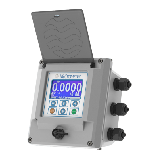
ProComm
ProComm
Electromagnetic
Flow Meter Converter
Installation, Operation and
Maintenance Manual
30124-60 Rev. 1.2
December 16, 2019
Standard Model
For use in non-hazardous locations
HL Model
For use in hazardous locations:
• Class I, Division 2, Groups A-D, T5
• Class I, Zone 2 IIC T5
www.mccrometer.com
Advertisement
Table of Contents

Subscribe to Our Youtube Channel
Related Manuals for McCrometer ProComm HL


Summary of Contents for McCrometer ProComm HL
- Page 1 Installation, Operation and Maintenance Manual 30124-60 Rev. 1.2 December 16, 2019 Standard Model For use in non-hazardous locations HL Model For use in hazardous locations: • Class I, Division 2, Groups A-D, T5 • Class I, Zone 2 IIC T5 www.mccrometer.com...
-
Page 2: Table Of Contents
Table of Contents SAFETY..................1 Safety Symbols . -
Page 3: Safety
When installing, operating, and maintaining McCrometer equipment where hazards may be present, you must protect yourself by wearing Personal Protective Equipment (PPE) and be trained to enter confined spaces. Examples of confined spaces are manholes, pumping stations, pipelines, pits, septic tanks, sewage digesters, vaults, degreasers, storage tanks, boilers, and furnaces. -
Page 4: Converter Description
ProComm CONVERTER DESCRIPTION 1.0 CONVERTER DESCRIPTION Read this entire manual prior to installation and/or changing any settings. Retain this manual in your records, DO NOT DISCARD. The signal converter is the reporting, input and output control device for the sensor. The converter allows the measurements, functional programming, control of the sensor and data recording to be communicated through the display and inputs &... -
Page 5: Mounting The Converter
ProComm INSTALLING THE CONVERTER AND CABLES Mounting the Converter Note: This applies to the remote mount converter only. If possible, mount the converter in an electronics shed or environmental enclosure. The sun shield should be oriented in a direction to reduce sun damage and ensure readability. Mount the converter to a solid surface using four bolts (Figure 2) or to a vertical or horizontal post using two clamps (Figure 3 and Figure 4). -
Page 6: Installing Cables Through Cable Glands And Conduit
Connections to the sensor must be made with cable supplied by McCrometer specifically for that purpose. Do not substitute the supplied cable with other types of cable, even for short runs. For repairs or Figure 7. -
Page 7: Cable Gland Assignment For Wiring Harnesses
ProComm INSTALLING THE CONVERTER AND CABLES Cable Gland Assignment for Wiring Harnesses To prevent signal interference and to keep the wiring organized, each cable gland is assigned for a specific wiring harness. Refer to the assignment diagrams (Figure 8, Figure 9) below when you route your cable run. Power Outputs Power... -
Page 8: Pulling Sensor Cable Through Electrical Conduit
ProComm INSTALLING THE CONVERTER AND CABLES Pulling Sensor Cable Through Electrical Conduit It is very important to protect the end of the sensor cable when pulling it through a conduit. Water can accumulate in low portions of conduit. Always use the factory supplied cable cover, or similar method, to seal the end of the cable against water when pulling the cable through conduit (see Figure 10). -
Page 9: Connecting Wires To Terminals
ProComm CONNECTING WIRES TO TERMINALS 3.0 CONNECTING WIRES TO TERMINALS WARNING! Ensure device is disconnected or circuit breaker is open per the requirements of IEC 60947-1 and IEC 60947-3 before opening the opening the converter. Terminal Block Diagram All connections are made on the terminal blocks. To access the terminal blocks, loosen the four screws on the front of the converter and open the front panel. -
Page 10: Wiring Diagrams
GROUND GROUND Harnesses pass Harnesses pass BLACK through cable glands through cable glands GREEN / GREEN / YELLOW BLACK ProComm to interior of converter WHITE YELLOW to interior of converter CONNECTING WIRES TO TERMINALS CABLE GLAND ASSIGNMENTS CABLE GLAND ASSIGNMENTS YELLOW WHITE YELLOW... -
Page 11: 4-20Ma Hook-Up
ProComm CONNECTING WIRES TO TERMINALS 4-20mA Hook-Up Isolated 4-20mA current loops are used to output flow data to external devices. Maximum load impedance is 1,000Ω, and the maximum voltage without load is 27VDC. The converter has the capability to detect a loss of load on this output. To disable this function set the value “mA Val. -
Page 12: Opto-Isolated Pulse Output Hook-Up
ProComm CONNECTING WIRES TO TERMINALS Opto-Isolated Pulse Output Hook-Up The outputs are open collector transistor outputs used to communicate with or activate external devices. • Opto-isolated output with collector and emitter terminals floating and freely connectable • Maximum switching voltage: 40 VDC •... -
Page 13: Optional Smart Output Hook Up
Elster Green Black shown at right. Itron Black Green • Signals and associated wire colors in the McCrometer Neptune Black Green SmartOutput™ interface cable are identified together in the top row of the table at right. Sensus Green Black •... -
Page 14: Converter Operation
ProComm CONVERTER OPERATION 4.0 CONVERTER OPERATION Starting up the Converter Before starting up the converter please verify the following: • Power supply voltage must correspond to that specified on the data plate (located on the side of the converter) • Electric connections must be wired as described in this manual •... -
Page 15: Front Panel Display
ProComm CONVERTER OPERATION Front Panel Display Push to change to the next screen display. Each button press changes the screen and cycles through the nine displays shown below. Screen 1 Unit of measure Flag Flow rate value Direction vertical marker Fluid velocity FLAG DESCRIPTION Empty pipe... - Page 16 ProComm CONVERTER OPERATION Screen 5 Totalizer total Screen 6 Screen 7 Totalizer partial Screen 8 Totalizer total Screen 9 Last key press returns to screen 1 Page 14 30124-60 Rev. 1.2 | 16DEC2019...
-
Page 17: Menu Structure
ProComm CONVERTER OPERATION Menu Structure The following is the menu structure for the ProComm converter. NOTE: Some menus change as options are enabled. 3-SCALES 10-DATA LOGGER MAIN MENU FS1= 10.1 D.logger en= OFF 1-Sensor Pls1= 10.2 Meas. units= ON 2-Units Tpls1= 10.3 Field separ.=... -
Page 18: Factory Set Key Code
ProComm CONVERTER OPERATION Factory Set Key Code The converter is delivered with key code L1 = 10000000, and with the “Quick start menu” enabled. Press the Enter/Esc key. The “Quick start" menu can be enabled or disabled. ATTENTION! It is very important to record any customized code as it CANNOT be retrieved if it is lost! Converter Access Code The access for programming the instrument is regulated by four access levels logically grouped. -
Page 19: Changing Settings On The Quick Start Menu
ProComm CONVERTER OPERATION Changing Settings on the Quick Start Menu The steps below demonstrate how to modify the Full Scale value from the Quick Start Menu. Beginning at one of the visualization screens, press the ENTER button to go to the Quick Start Menu. QUICK START ENTER S.model=... -
Page 20: Changing Main Menu Settings
ProComm CONVERTER OPERATION Changing Main Menu Settings The steps below demonstrate how to modify the Full Scale value from the Main Menu. Beginning at one of the visualization screens, Use the UP and DOWN buttons to enter numbers. Use press the ENTER button. the LEFT and RIGHT buttons to move to each position. -
Page 21: Menu Descriptions
[SIPOS] This function is active with POS.1.3 on “Insertion”. Function Description Note: For ProComm users who want to use MCP software, it can be downloaded from the McCrometer Web site under the category of Installation, Operation, and Maintenance Manuals. https://mccrometer.hachuat.com/asset-get.download-en.jsa?id=54942158007... - Page 22 ProComm MENU DESCRIPTIONS Menu Function Access Converter Function Code Function Description Position Name Level Command Coils Sets the excitation coils current. This [CEXCC] [C.Curr.= mA Ex.Current function is active if the sensor model xxx.x] 1.14 is NOT present on the sensor's table standard parameters.
-
Page 23: Menu 2 - Units
ProComm MENU DESCRIPTIONS Menu 2 - Units Menu Function Access Converter Function Code Function Description Position Name Level Command Diameter Sets the sensor diameter unit of [SDIUM] [Diam.= mm] measurement: mm or inch. S.cable Sets the sensor cable length for [SCAUM] [S.Cable= m] length unit of... -
Page 24: Menu 3 - Scales
ProComm MENU DESCRIPTIONS Menu 3 - Scales Menu Function Access Converter Function Code Function Description Position Name Level Command Full Rate Full The full scale is used to indicate to [FRFS1] [FS1= g/s4908.7] Scale the meter’s maximum flow rate; a volume per time is required. - Page 25 ProComm MENU DESCRIPTIONS Menu Function Access Converter Function Code Function Description Position Name Level Command Output Pulse Pls1 is active with POS.7.1. This [OP1PV] [Pls1=g1000.00] enables and sets the pulse value on channel 1. This function allows the user to set a signal (a pulse) to be given from the converter when a defined amount of liquid has passed through the sensor.
-
Page 26: Menu 4 - Measure
ProComm MENU DESCRIPTIONS Menu 4 - Measure Menu Function Access Converter Function Code Function Description Position Name Level Command Damping This setting adjusts how quickly the [MFDMP] [Damping=SMART] converter responds to momentary changes in flow. Settings range from Damping=OFF (immediate response but noisy signal) to 1000s (slow response to changes in flow but quiet signal. - Page 27 ProComm MENU DESCRIPTIONS Menu Function Access Converter Function Code Function Description Position Name Level Command Cut-off Sets the low flow cutoff threshold. [MFCUT] [Cutoff=%00.1] threshold This function is useful to avoid erroneous totalizer increases at zero flow due to electrical noise. Note: The allowed range for this function is 0-25% of full scale set.
-
Page 28: Menu 5 - Alarms
ProComm MENU DESCRIPTIONS Menu 5 - Alarms Menu Function Access Converter Function Code Function Description Position Name Level Command Maximum Sets the maximum value alarm [FRAXP] [Max+=dm3/s] flow rate for direct flow rate setting. When threshold the flow rate value exceeds such direct the threshold, an alarm message is generated. -
Page 29: Menu 6 - Inputs
ProComm MENU DESCRIPTIONS Menu Function Access Converter Function Code Function Description Position Name Level Command Hysteresis Sets the hysteresis threshold set [ATHYS] [Hysteresis=%03] for the minimum and maximum flow rate alarms. The value of this parameter is expressed as percentage of the full scale value and may be set from 0 to 25%. - Page 30 ProComm MENU DESCRIPTIONS Menu Access Converter Function Code Function Name Function Description Position Level Command [Meas.lock=OFF] When this function is active (ON), [MSLIE] [Meas.lock=OFF] applying a voltage to the on input terminals, the measurement is stopped and the meter will display zero flow.
-
Page 31: Menu 7 - Outputs
ProComm MENU DESCRIPTIONS Menu 7 - Outputs Menu Access Converter Function Code Function Name Function Description Position Level Command Output 1 Sets the selection for Output 1. [OUT1F] [Out1=PULSES+] function The functions are listed in the selection table below. Output 2 Sets the selection for Output 2. - Page 32 ProComm MENU DESCRIPTIONS Menu Access Converter Function Code Function Name Function Description Position Level Command Current output This function sets the current [OUT2F] [Out mA2=4_22+/-] option and range output 2. This function is optional and will not appear unless the option has been requested. There are three fields to modify for this function: •...
-
Page 33: Menu 8 - Communication
ProComm MENU DESCRIPTIONS Menu Access Converter Function Code Function Name Function Description Position Level Command Analog Output1 Sets the full scale value for analog [AO1FS] [A1S=dm3/s full scale output 1 independently of the 4.9087] main scale of the instrument Analog Output2 Sets the full scale value for analog [AO2FS] [A2S=dm3/s... -
Page 34: Menu 9 - Display
ProComm MENU DESCRIPTIONS Menu 9 - Display Menu Access Converter Function Code Function Name Function Description Position Level Command Sets the language selection. There Language for all are 2 languages available: EN = [LLANG] [Language=EN] English, IT = Italian. Sets the display contrast. The contrast can change according Display Contrast [DCNTR]... - Page 35 ProComm MENU DESCRIPTIONS Menu Access Converter Function Code Function Name Function Description Position Level Command The following functions are activated by [D.logger en= ON] 10.2 Unite of Measure [DLUME] Measure unit recording enable [Meas. units= ON] 10.3 Field separator This function will set the separator [DLFSC] character character between data logger...
- Page 36 ProComm MENU DESCRIPTIONS DATA LOGGER: ONLY MCP FUNCTIONS Menu Access Converter Function Code Function Name Function Description Position Level Command LoG All Log all events information. This Information function save in the event file all [LGAIE] [MCP ONLY] Enable MCP commands. USING DATA LOGGER BY MCP INTERFACE Data are stored on micro SD card;...
-
Page 37: Menu 11 - Functions
ProComm MENU DESCRIPTIONS 5.11 Menu 11 - Functions Menu Access Converter Function Code Function Name Function Description Position Level Command Totalizer Total Resets the total direct totalizer for 11.1 [VTTPR] [T+ reset] Positive reset direct flow rate (+) Totalizer Par. Resets the total partial totalizer for 11.2 [VTPPR]... -
Page 38: Menu 13 - System
ProComm MENU DESCRIPTIONS Menu Access Converter Function Code Function Name Function Description Position Level Command 12.4 Flow Rate Enables flow rate simulation. [Flow sim.=ON] Simulation With this function, it is possible to generate an internal signal that simulates the flow rate and allows [MSIEN] for testing the outputs and all the connected instruments. -
Page 39: Biv (Built-In Verification)
BIV, abbreviation of Built In Verificator, is available as option on the ProComm converter. Note: For ProComm users who want to use BIV software, it can be downloaded from the McCrometer Web site under the category of Installation, Operation, and Maintenance Manuals. -
Page 40: Isobiv Interface
ISOBIV Interface To start the ISOBIV interface, wait till the connection with the ProComm will be realized. Software update: With a set of dedicated commands it is possible to connect to a HTTP server and to download automatically a new software release and/or command list. Once invoked, the process is performed automatically; the new software is checked, and in case of error the process is aborted and the instrument resumes the normal operation. -
Page 41: Error Codes
ProComm ERROR CODES 7.0 ERROR CODES The codes are in hexadecimal format, the meaning is given for each bit. There are several possible error simultaneous combinations (more bits active) then that will give the combined numerical codes. CODE ANOMALIES DESCRIPTION ACTION TO TAKE 0000 NO ERROR... -
Page 42: Alarm Messages
ProComm ALARM MESSAGES 8.0 ALARM MESSAGES MESSAGE CAUSES ACTION TO TAKE NO ALARMS All works regularly [000] SYSTEM RESTART [001] INTERNAL PS FAIL Internal supply voltage error Contact the service [002] CLOCK NOT SET System Clock not set Set the system clock from the converter menu 13 (see also MCP function ). - Page 43 ProComm ALARM MESSAGES MESSAGE CAUSES ACTION TO TAKE [022] BATTERY V>MAX Battery voltage (rechargeable)> max. Contact customer service to replace the Allowed battery [023] BATTERY I>MAX Battery charge current> max. allowed Contact customer service to replace the battery [024] MAIN PS V.ERR Main supply voltage (+ 5V) out of Contact customer service tolerance.
-
Page 44: Specifications
• Conduit option: 1/2” NPT threaded connections Sensor Cable Lengths Sensor Cable Lengths Standard 25’ McCrometer supplied submersible cable with each remote mount unit. Standard 25’ McCrometer supplied submersible cable with each remote mount unit. Optional Up to 500 feet, or 25 feet max for battery powered. -
Page 45: Keypad And Display
Temperature Range display Operating and Note regarding cable length: McCrometer recommends minimizing cable length. Electromagnetic flow meters may have -20° to 60° C (-4° to 140° F) storage unfavorable signal strength to noise ratio in electrically noisy environments. Longer lengths of cable increase the likelihood of interference. -
Page 46: Dimensions
ProComm DIMENSIONS 10.0 DIMENSIONS Meter Mount Converter Dimensions Height 6.9” (20.1 cm) Width7.2” (18.3 cm) Depth 6.2” (15.7 cm) 6.2" 6.9" 3" 4.2" 3.1" 3.1" 7.2" 6.2" 140º 10.5" 5.6" 3.1" Page 44 30124-60 Rev. 1.2 | 16DEC2019... - Page 47 ProComm DIMENSIONS Remote Mount Converter Dimensions Height 7.3" (18.5 cm) Width 8.5" (21.6 cm) Depth 4.3" (10.9 cm) 4.3" 7.0" 2.25" C TO C 7.3" 7.5" C TO C 8.5" 140º 10.1" 8.2" Page 45 30124-60 Rev. 1.2 | 16DEC2019...
-
Page 48: Returning A Unit For Repair
• Call the McCrometer Customer Service Department at 1-800-220-2279 and ask for a Return Authorization (RA) number. • Ship the meter in the original packaging, if possible. Do not ship manuals, power cords, or other parts with your unit unless required for repair. -
Page 49: Troubleshooting Guide
ProComm TROUBLESHOOTING GUIDE 12.0 TROUBLESHOOTING GUIDE WARNING! Ensure device is disconnected or circuit breaker is open per the requirements of IEC 60947-1 and IEC 60947-3 before opening the opening the converter. Problem Troubleshooting Steps Not getting expected 4-20mA output • Ensure the wiring is firmly connected on the 4-20mA output terminals •... -
Page 50: Warranty Statement
ProComm WARRANTY STATEMENT WARRANTY STATEMENT McCrometer warrants that this product will be free from Purchaser’s sole remedy and manufacturer’s sole obligation defects in material and workmanship for a period 12 for alleged product failure, whether under warranty months from the date the equipment was first installed,... - Page 51 ™ Copyright © 2001-2019 McCrometer, Inc. All printed material should not be changed or altered without permission of McCrometer. Any published pricing, technical data, and instructions are subject to change without notice. Contact your McCrometer representative for current pricing, technical data, and instructions.
Need help?
Do you have a question about the ProComm HL and is the answer not in the manual?
Questions and answers