McCrometer ProComm User Manual
Hart protocol convertor
Hide thumbs
Also See for ProComm:
- Installation, operation and maintenance manual (51 pages) ,
- Installation, operation and maintenance manual (29 pages)

Subscribe to Our Youtube Channel
Related Manuals for McCrometer ProComm


Summary of Contents for McCrometer ProComm
- Page 1 Hart Protocol User Manual For use with ProComm Converter 30125-48 Rev. 1.0 August 5, 2021...
-
Page 2: Table Of Contents
Table of Contents SAFETY . . . . . . . . . . . . . . . . . . . . . . . . . . . . . . . . . . . . . . . . . . . . 1 1 .0 Introduction . -
Page 3: Safety
IMPORTANT When installing, operating, and maintaining McCrometer equipment where hazards may be present, you must protect yourself by wearing Personal Protective Equipment (PPE) and be trained to enter confined spaces. Examples of confined spaces are manholes, pumping stations, pipelines, pits, septic tanks, sewage digesters, vaults, degreasers, storage tanks, boilers, and furnaces. -
Page 4: Introduction
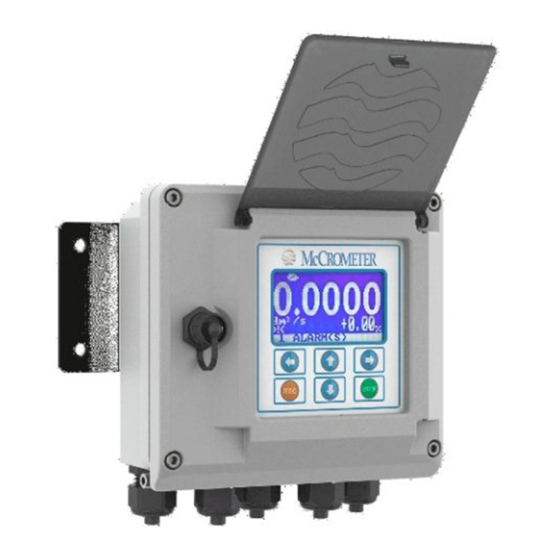
30124-60, ProComm IOM Manual 1 .6 Device Identification The ProComm converter is provided with a waterproof case where the device is already installed. The name plate is located on the side of the case and indicates the model name and revision. 2 .0 Product Overview The ProComm converter is a flow meter transmitter, with a 4-to-20mA output. -
Page 5: Product Interfaces
Analog Output 1: Flow Rate The two-wire 4-to-20mA current loop is connected on two terminals. Refer to the ProComm IOM manual for connection details. This output represents the process flow rate measurement, linearized and scaled, according to the configured range of the instrument, and it corresponds to the primary variable. -
Page 6: Device Variables
NOTE All Unit Codes for these variables can be found in Table 2.68/2.71, HCF_SPEC-183. 5 .0 Dynamic Variables This ProComm converter using the Hart protocol uses four dynamic variables. These variables are linked to the device variables. Device Dynamic Variable... -
Page 7: Status Information
Status Information 6 .0 Status Information 6 .1 Device Status The converter sets a device status variable to indicate certain conditions. Device Status The PV is beyond its operating limits The loop current has reached its upper (or lower) endpoint limit and cannot increase (or decrease) any further The loop current is being held at a fixed value and is not responding to process variations "More Status Available"... -
Page 8: Common-Practice Commands
Common-Practice Commands 8 .0 Common-Practice Commands 8 .1 Supported Commands The Field Device manages the following Common-Practice Commands: Command Details Read Device Variables Write Primary Variable Damping Value Write Primary Variable Range Value Enter/Exit Fixed Current Mode Perform Self Test Perform Device Reset Write Primary Variable Units Write Primary Variable Transfer Function... -
Page 9: Device-Specific Commands
This command allows the user to enable or disable the write protection flag. The Command #128 takes effect only if the write protect flag is enabled. The parameter that allows the change is set via display in the specific menu. Refer to ProComm IOM Manual for the converter function code and MCP command. Byte... - Page 10 Command #130: Reset Totalizer This command allows the user to reset a specific totalizer. It takes effect only if the selected totalizer is enable to be reset. Refer to ProComm IOM Manual for the converter function code and MCP command. Byte...
-
Page 11: Tables
Tables Command #134: Read Density This command returns the fluid density setting in fixed unit (Kg/l). Byte Format Description Request Data Bytes Enum Unit code (fixed) Response Data Bytes 1 - 4 Float Density Command-Specific Success No command-specific errors Response Codes Command #135: Read Flow Direction This command returns the flow direction. -
Page 12: Flow Direction
Performance 10 .3 Flow Direction Value Description Flow Direction Positive Flow Direction Negative 11 .0 Performance 11 .1 Sampling Rates Typical sampling rates are shown in the following table. Variable Sampling Rate Primary Flow Rate Sensor Sample 20 per second PV Digital Value Calculation 20 per second SV Digital Value Calculation... -
Page 13: Command Response Times
Write-protection is provided with Device Specific Command#128. This command takes effect only if the writing of WP flag is enabled. The parameter that allows the change is set via display in the specific menu. Refer to the ProComm Converter IOM manual for more details. -
Page 14: Appendix A - Capability Checklist
APPENDIX A - CAPABILITY CHECKLIST APPENDIX A - CAPABILITY CHECKLIST Device Type Transmitter HART Revision Device Description available Number and Type of Sensors Number and Type of Actuators None Number and Type of Host Side Signals 1: 4 - 20mA Analog Number of Device Variables Number of Dynamic Variables Mappable Dynamic Variables? - Page 15 ™ Copyright © 2021 McCrometer, Inc. All printed material should not be changed or altered without permission of McCrometer. Any published pricing, technical data, and instructions are subject to change without notice. Contact your McCrometer representative for current pricing, technical data, and instructions.
Need help?
Do you have a question about the ProComm and is the answer not in the manual?
Questions and answers