
Related Manuals for DuraVent DuraPlus HTC


Summary of Contents for DuraVent DuraPlus HTC
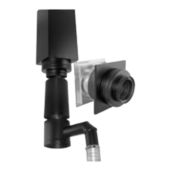
- Page 1 Installation Instructions Combustion Air System Combustion Air System (CAS) brings in outside air for wood-burning appliances. Used with the DuraPlus HTC chimney system.
- Page 2 Read through all of these instructions before We welcome any comments regarding matters beginning your installation. Failure to install pertaining to our DuraVent products. as described in this instruction will void the We welcome any ideas, input or complaints manufacturer’s warranty, and may have an and I’ll make sure that someone responds...
- Page 3 CombustIon AIr system for DurAplus htC For the most up-to-date installation instructions, see www.duravent.com CONTENTS Clearances; Permits; Equipment & Materials; Installation Notes ..4 DuraPlus HTC Chimney CAS Installation; General Installation Requirements ......... . 5 Through-The-Ceiling Installations..
-
Page 4: Installation Notes
Roofing Nails safely into a listed chimney. The CAS system #8, 2-1/2” & 1-1/2” Wood Screws is available for the DuraPlus HTC chimney INSTALLATION NOTES system. Proper planning for your Combustion Air CLEARANCES... - Page 5 These CAS installation instructions are intended AT LEAST 6" to be used with the full installation instructions CLEARANCE BETWEEN CAS for DuraPlus HTC. Except as described in STOVE PIPE AND WALL these installation instructions, always follow the DuraPlus HTC installation instructions for a safe installation.
- Page 6 Support Box. MAINTAIN AT LEAST The CAS Ceiling Support can support up to 8" CLEARANCE 40-ft of DuraPlus HTC chimney. The CAS BETWEEN CAS FOR THRU- STOVE PIPE AND Ceiling Support should be located directly...
- Page 7 installation, the combustion air is drawn in AIR ENTERS UNDER THE STORM COLLAR through the flashing, underneath the Storm THROUGH THE FLASHING FOR ATTIC Collar (Fig 5). CHASE INSTALLATIONS Step 3. Install CAS Connector Pipe. After the CAS Ceiling Support is installed and the stove is located, the CAS Connector Pipe can be installed.
- Page 8 ATTACH ELBOW TO BRANCH OF ADAPTER WITH (3) SCREWS PROVIDED. ATTACH FLEx TO STOVE AND ELBOW USING HOSE CLAMPS PROVIDED Figure 8 of the Adapter. Additional lengths of CAS Connector pipe can then be installed using the screws provided to secure the pipe lengths (male end up, female end down) (Fig 7).
- Page 9 CAS Ceiling Support (3) 3/8” screws provided. If an offset in the as normally directed in the full DuraPlus HTC connector pipe is needed, CAS 45-degree Installation Instructions. You should install and 90-degree elbows are available.
- Page 10 the field-fabricated tube over the inner portion THROUGH-THE-WALL of the Wall Thimble and then slide the outer INSTALLATIONS portion of the Wall Thimble into the field- Step 1. Determine location for CAS Wall fabricated tube to complete the continuous Thimble. The CAS Wall Thimble should be tube through the wall.
- Page 11 Tee with the Tee Support as CHASE AIR INTAKE WITH RODENT GUARD detailed in the full DuraPlus HTC installation PROVIDES A 6" DIAMETER OPENING instructions. Continue to install the remainder FOR VENTILATION INTO of the chimney system as described in those CHASE.
- Page 12 (10) years. This warranty does not cover normal wear and tear, smoke damage or damage caused by chimney fires, acts of God, or any product that was: (1) purchased other than from an authorized DuraVent dealer, retailer or distributor;...
Need help?
Do you have a question about the DuraPlus HTC and is the answer not in the manual?
Questions and answers