Ceragon FibeAir IP-20G Installation Manual
Hide thumbs
Also See for FibeAir IP-20G:
- Technical description (266 pages) ,
- Installation manual (36 pages) ,
- User manual (20 pages)

Related Manuals for Ceragon FibeAir IP-20G


Summary of Contents for Ceragon FibeAir IP-20G
-
Page 1: Installation Guide
Installation Guide ® FibeAir IP-20G ® FibeAir IP-20G Assured Doc ID: DOC-00041192 Rev E.08 June 2018 © Copyright 2018 by Ceragon Networks Ltd. All rights reserved. -
Page 2: Information To User
Installation Guide for FibeAir IP-20G, FibeAir IP-20G Assured Notice This document contains information that is proprietary to Ceragon Networks Ltd. No part of this publication may be reproduced, modified, or distributed without prior written authorization of Ceragon Networks Ltd. This document is provided as is, without warranty of any kind. -
Page 3: Table Of Contents
Installation Guide for FibeAir IP-20G, FibeAir IP-20G Assured Table of Contents 1. FibeAir IP-20G Hardware Overview................11 Ethernet Traffic Interfaces ......................12 Ethernet Management Interfaces ....................13 1.2.1 Management Interface Cable Options ..................13 TDM Interfaces (E1/DS1 1x16) (Optional) .................. 13 Radio Interfaces ......................... - Page 4 Installation Guide for FibeAir IP-20G, FibeAir IP-20G Assured Configuration ..........................33 Applying a Pre-Defined Configuration File ................. 34 7. Specifications ......................36 Environmental Specifications for IDU ..................36 Environmental Specifications for RFU ..................36 Mechanical Specifications ......................37 Power Consumption Specifications ................... 38 8.
- Page 5 Installation Guide for FibeAir IP-20G, FibeAir IP-20G Assured List of Figures Figure 1: IP-20G Front Panel and Interfaces Figure 2: Management Interface Pin Connections Figure 3: IDU (Full Configuration) Figure 4: Power Supply Grounding Figure 5: Correct Wiring of Power Connector Figure 6: Connecting the Power Cable Figure 7: IP-20G with Unit Redundancy –...
- Page 6 Installation Guide for FibeAir IP-20G, FibeAir IP-20G Assured List of Tables Table 1: 2 x FE Splitter Cable Marketing Model ..................13 Table 2: Y-Cable for Electrical Splitter Mode FE Traffic Interface Protection ........27 Table 3: Y-Cable for E1/DS1 Protection ....................27 Table 4: Splitter Cable for Protection and Management ...............
- Page 7 Installation Guide for FibeAir IP-20G, FibeAir IP-20G Assured Safety Precautions & Declared Material General Equipment Precautions Use of controls, adjustments, or performing procedures other than those specified herein, may result in hazardous radiation exposure. When working with a FibeAir IDU, note the following risk of electric shock and energy hazard: Disconnecting one power supply disconnects only one power supply module.
- Page 8 Installation Guide for FibeAir IP-20G, FibeAir IP-20G Assured This equipment contains components which are sensitive to "ESD" (Electro Static Discharge). Therefore, ESD protection measures must be observed when touching the IDU. Anyone responsible for the installation or maintenance of the FibeAir IDU must use an ESD Wrist Strap.
- Page 9 Installation Guide for FibeAir IP-20G, FibeAir IP-20G Assured Restricted Access Area: DC powered equipment should only be installed in a Restricted Access Area. Installation Codes: The equipment must be installed according to country national electrical codes. For North America, equipment must be installed in accordance to the US National Electrical Code, Articles 110-16, 110-17 and 110-18, and the Canadian Electrical Code, Section 12.
-
Page 10: About This Guide
Consult the Release Notes for the functionality supported in the specific release you are using. Target Audience This guide is intended for use by personnel of all levels certified by Ceragon personnel such as system engineers, technicians, or supervisors. Related Documents •... -
Page 11: Fibeair Ip-20G Hardware Overview
Installation Guide for FibeAir IP-20G, FibeAir IP-20G Assured FibeAir IP-20G Hardware Overview FibeAir IP-20G is a compact unit that fits in a single rack unit, with a passive cooling system that eliminates the need for fans. An IP-20G system consists of an IP-20G indoor unit (IDU) and one or two radio frequency units (RFUs). -
Page 12: Ethernet Traffic Interfaces
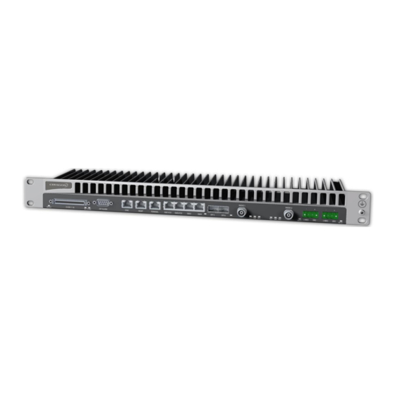
Installation Guide for FibeAir IP-20G, FibeAir IP-20G Assured Ethernet Traffic Interfaces The front panel of the FibeAir IP-20G contains four electrical and two optical GE Ethernet traffic interfaces: 2 x GE dual mode electrical or cascading interfaces (RJ-45) – GbE1/CS1, •... -
Page 13: Ethernet Management Interfaces
SPL-ETH-CBL Ethernet split cable rohs WA-0245-0 TDM Interfaces (E1/DS1 1x16) (Optional) Optionally, FibeAir IP-20G can be ordered with an MDR69 connector in which 16 E1/DS1 interfaces are available (ports 1 through 16). Page 13 of 49 Ceragon Proprietary and Confidential... -
Page 14: Radio Interfaces
Radio 2. Power Interfaces FibeAir IP-20G receives an external supply of -48V current via one or two power interfaces (the second power interface is optional for power redundancy). The IP- 20G monitors the power supply for under-voltage and includes reverse polarity protection, so that if the positive (+) and negative (-) inputs are mixed up, the system remains shutdown. -
Page 15: External Alarms
Installation Guide for FibeAir IP-20G, FibeAir IP-20G Assured External Alarms IP-20G includes a DB9 dry contact external alarms interface. The external alarms interface supports five input alarms and a single output alarm. The input alarms are configurable according to: 1 Intermediate... -
Page 16: Fibeair Ip-20 Assured Platform
Installation Guide for FibeAir IP-20G, FibeAir IP-20G Assured FibeAir IP-20 Assured Platform Ceragon’s FibeAir ® IP-20 Assured platform enhances network reliability and security, ensuring that mission-critical networks maintain availability, and protecting the confidentiality and integrity of their users’ data. The FibeAir IP-20 Assured platform is compliant with FIPS 140-2, including: •... -
Page 17: Preparing For Installation
Installation Guide for FibeAir IP-20G, FibeAir IP-20G Assured Preparing for Installation This section provides instructions for transporting, inspecting, and unpacking the equipment for an IP-20G system prior to installation. Transportation/Storage The equipment cases are prepared for shipment by air, truck, railway and sea, suitable for handling by forklift trucks and slings. -
Page 18: Unpacking Equipment At The Site
To avoid malfunctioning or personnel injuries, equipment or accessories/kits/plug-in unit installation, requires qualified and trained personnel. Changes or modifications not expressly approved by Ceragon Networks could void the user's authority to operate the equipment Where special cables, shields, adapters and grounding kits are supplied or described in this manual, these items must be used, to comply with the relevant regulations. -
Page 19: Installing The Ip-20G Idu
Installation Guide for FibeAir IP-20G, FibeAir IP-20G Assured Installing the IP-20G IDU This section provides instructions for installing a FibeAir IP-20G IDU. Figure 3: IDU (Full Configuration) Kits required to perform the installation Description Quantity IP-20G chassis 19" rack / sub-rack... -
Page 20: Installing The Ip-20G Idu In The Rack (19")
Installation Guide for FibeAir IP-20G, FibeAir IP-20G Assured Installing the IP-20G IDU in the Rack (19") 1 Insert and hold the IP-20G IDU in the rack, as shown in the following figures. Use four screws (not supplied with the installation kit) to fasten the IDU to the rack. -
Page 21: Grounding The Ip-20G
Installation Guide for FibeAir IP-20G, FibeAir IP-20G Assured Grounding the IP-20G Connect a grounding wire first to the single-point stud shown in the figure below, and then to the rack, using a single screw and two washers. Verify that the grounding resistance is 0-2 ohms. -
Page 22: Replacing An Ip-20G Idu Or Sm-Card
Installation Guide for FibeAir IP-20G, FibeAir IP-20G Assured Replacing an IP-20G IDU or SM-Card If you should need to replace the IP-20G IDU, you must first remove the SM-Card Cover so that you can insert it into the new IDU. - Page 23 Installation Guide for FibeAir IP-20G, FibeAir IP-20G Assured 4 Gently place the SM-Card Cover in its place and tighten the screws, using a Phillips screwdriver. Page 23 of 49 Ceragon Proprietary and Confidential...
-
Page 24: Connecting The Power Cable
Power supply grounding should be in according with the following figure: Figure 4: Power Supply Grounding FibeAir IP-20G utilizes a single-feed power interface. Optionally, IP-20G can be ordered with a second power interface for power redundancy. A power cable connector is included with the IP-20G unit. -
Page 25: Figure 5: Correct Wiring Of Power Connector
Installation Guide for FibeAir IP-20G, FibeAir IP-20G Assured Figure 5: Correct Wiring of Power Connector 4 Insert the wires into the connector. 5 Secure the wires in the connector with the screws. 6 Plug the connector into the IP-20G power interface and tighten the two screws on the sides of the connector to secure the connector. -
Page 26: Power Supply Notes
Installation Guide for FibeAir IP-20G, FibeAir IP-20G Assured Power Supply Notes When selecting a power source, the following must be considered: • Voltage range: -40 VDC to -60 VDC. Recommended: Availability of a UPS (Uninterrupted Power Source), battery • backup, and emergency power generator. -
Page 27: Cabling Requirements For Unit Redundancy
Installation Guide for FibeAir IP-20G, FibeAir IP-20G Assured Cabling Requirements for Unit Redundancy Cabling for Ethernet Interfaces For Ethernet Splitter Mode, the following Y-cable must be connected to the relevant interfaces on the active and standby units: Table 2: Y-Cable for Electrical Splitter Mode FE Traffic Interface Protection... -
Page 28: Inter-Idu Protection Connectivity And Management
Installation Guide for FibeAir IP-20G, FibeAir IP-20G Assured Inter-IDU Protection Connectivity and Management IP-20G units in a redundancy configuration must have their CPUs interconnected in order to synchronize their protection status. The same IP address is used for both IP-20G units, to ensure that management is not lost in the event of switchover. -
Page 29: Performing Initial Configuration
Installation Guide for FibeAir IP-20G, FibeAir IP-20G Assured Performing Initial Configuration This section describes how to establish a management connection with the IP-20G unit and lists the configuration steps that should be performed in order to enable basic radio connectivity. For detailed configuration instructions, refer to the User Guide for Chassis-Based Systems: FibeAir IP-20N, IP-20A, IP-20LH, and Evolution IP-20LH. -
Page 30: Connecting To The Unit With A Lan Connection
6.1.2 Connecting to the Unit with a LAN Connection FibeAir IP-20G contains two FE management interfaces, which connect to a single RJ-45 physical connector on the front panel (MGMT). For details on which type of cable to use to utilize either one or both management interfaces, refer to Management Interface Cable Options on page 13. -
Page 31: Logging On
Installation Guide for FibeAir IP-20G, FibeAir IP-20G Assured Logging On 1 Open an Internet browser (Internet Explorer or Mozilla Firefox). 2 Type in the default IP address "192.168.1.1" in the Address Bar. Figure 10: Login Window 3 Enter the following values:... -
Page 32: Changing Your Password
In addition to the Admin password, there is an additional password protected user account, “root user”, which is configured in the system. The root user password and instructions for changing this password are available from Ceragon Customer Support. It is strongly recommended to change this password. -
Page 33: Configuration
Installation Guide for FibeAir IP-20G, FibeAir IP-20G Assured Configuration Before connection over the radio hop is established, it is of high importance that the elements are assigned a dedicated IP address, according to an IP plan for the total network. -
Page 34: Applying A Pre-Defined Configuration File
A pre-defined configuration file can be prepared for multiple IP-20 units, with the relevant configuration details specified and differentiated per-unit. The pre-defined configuration file is generated by Ceragon Global Services and provided as a service. The pre-defined configuration file must be compatible with the CeraOS version the IP-20 device is running. -
Page 35: Figure 13: Quick Configuration - From File Page - Configuration File Loaded
Installation Guide for FibeAir IP-20G, FibeAir IP-20G Assured 2 Click Browse, and select the configuration file for your unit. Figure 13: Quick Configuration – From File Page – Configuration File Loaded 3 In the Device List field, select the IP-20 unit you are configuring. -
Page 36: Specifications
Installation Guide for FibeAir IP-20G, FibeAir IP-20G Assured Specifications Environmental Specifications for IDU Operating: ETSI EN 300 019-1-3 Class 3.2 • • Temperature: -5C (23F) to 55C (131F) – Temperature range for continuous operating temperature with high reliability. -25C (-13F) to 65C (149F) – Temperature range for exceptional temperatures, tested successfully, with limited margins. -
Page 37: Mechanical Specifications
Installation Guide for FibeAir IP-20G, FibeAir IP-20G Assured Mechanical Specifications Table 5: IDU Mechanical Specifications IDU Dimensions Height: 44 mm/1.73” (1RU) Width: 426 mm/16.77” Depth: 180 mm/7.08” Weight: 2.5 kg/5.5 lbs. IDU-RFU Coaxial cable RG-223 (300 ft), Belden 9914/RG-8 Connection (1000 ft) or equivalent, TNC connectors to the IDU, N-type connectors (male) to the RFU. -
Page 38: Power Consumption Specifications
Installation Guide for FibeAir IP-20G, FibeAir IP-20G Assured Power Consumption Specifications The following table shows the maximum power consumption for IP-20G IDU and supported RFUs. The++ maximum power consumption for the entire system is the sum of the IDU and the RFUs connecting to it. -
Page 39: Acceptance & Commissioning Procedures
Installation Guide for FibeAir IP-20G, FibeAir IP-20G Assured Acceptance & Commissioning Procedures This chapter provides Ceragon's recommended Acceptance and Commissioning Procedure for IP-20. Acceptance and commissioning should be performed after initial setup is complete. The purpose of this procedure is to verify correct installation and operation of the installed link and the interoperability with customer end equipment. -
Page 40: Site Acceptance Procedure
Installation Guide for FibeAir IP-20G, FibeAir IP-20G Assured Site Acceptance Procedure The purpose of the following procedures is to verify that all installation requirements were noted and checked. Following this procedure will ensure proper, long-lasting, and safe operation of the product. - Page 41 Installation Guide for FibeAir IP-20G, FibeAir IP-20G Assured SITE ACCEPTANCE CHECKLIST (continued) 4. RADIO FREQUENCY UNIT (RFU) (Direct or Remote Type of RFU mount: mount) RFU is securely mounted to the antenna or pole RFU is grounded as per installation instructions RFU‘s polarization is as per link requirements...
- Page 42 Installation Guide for FibeAir IP-20G, FibeAir IP-20G Assured SITE ACCEPTANCE CHECKLIST (continued) 7. FLEXIBLE WAVEGUIDE Overall flexible WG length: Flexible WG type: Flexible WG is connected securely to RFU and Antenna Flexible WG connector is weather-proofed (sealed) at the RFU...
- Page 43 Installation Guide for FibeAir IP-20G, FibeAir IP-20G Assured SITE ACCEPTANCE CHECKLIST (continued) 11. REMARKS/NOTES 12. GENERAL INFORMATION Name: Title: Site accepted by: Company: Signature: Date: Name: Title: Site approved by: Company: Signature: Date: Page 43 of 49 Ceragon Proprietary and Confidential...
-
Page 44: Site Acceptance Checklist Notes
Installation Guide for FibeAir IP-20G, FibeAir IP-20G Assured Site Acceptance Checklist Notes The following notes provide important additional information about the Site Acceptance Checklist. 1 Antenna Mounting Mounting pole is of sufficient height to clear local obstructions, such as •... - Page 45 Installation Guide for FibeAir IP-20G, FibeAir IP-20G Assured • The main traffic connections are correctly terminated and crimped as per cable and connector manufacturer instructions. All fiber optic patch leads should be routed carefully and efficiently, using conduits to prevent damage to the cables.
-
Page 46: Radio Link Commissioning Procedure
Connect Ethernet Packet Analyzer to the GbE port. Use physical loop at remote end (or connect second analyzer). Run Packet Loss test for at least one hour (load rate as per Ceragon's specifications for the chosen MRMC). Connect Ethernet Packet Analyzer to the FE port. Use physical loop at remote •... -
Page 47: Ip-20 Commissioning Log
Maintaining the Commissioning Log is important for tracking your installations, and to provide essential data for Ceragon Networks. Upon completing the Commissioning Log, send the log to Ceragon support center at support@ceragon.com. IP-20 LINK COMMISSIONING LOG 1. - Page 48 Installation Guide for FibeAir IP-20G, FibeAir IP-20G Assured 3. ANTENNA AND RFU MOUNT Site 1 Site 2 Antenna vendor and model: Antenna size: Mounting type: Mounting losses: 4. LINK PARAMETERS Site 1 Site 2 Link distance: Rain zone: Expected RSL (dBm):...
- Page 49 Installation Guide for FibeAir IP-20G, FibeAir IP-20G Assured 8. INSTALLATION INFORMATION Name: Company: Installed by: Date: Signature: Name: Company: Commissioned by: Date: Signature: Page 49 of 49 Ceragon Proprietary and Confidential...
Need help?
Do you have a question about the FibeAir IP-20G and is the answer not in the manual?
Questions and answers