
Subscribe to Our Youtube Channel
Related Manuals for Ceragon FibeAir IP-20F


Summary of Contents for Ceragon FibeAir IP-20F
- Page 1 Installation Guide ® FibeAir IP-20F February 2020 | Rev A.06 © Copyright 2020 by Ceragon Networks Ltd. All rights reserved.
- Page 2 Installation Guide for FibeAir IP-20F Notice This document contains information that is proprietary to Ceragon Networks Ltd. No part of this publication may be reproduced, modified, or distributed without prior written authorization of Ceragon Networks Ltd. This document is provided as is, without warranty of any kind.
-
Page 3: Table Of Contents
Installation Guide for FibeAir IP-20F Table of Contents 1. FibeAir IP-20F Hardware Overview ................11 Ethernet Traffic Interfaces ......................12 Ethernet Management Interfaces ....................13 1.2.1 Management Interface Cable Options ..................13 E1/DS1 Interface ........................14 STM-1/OC-3 Interfaces ......................15 Radio Interfaces ......................... - Page 4 Installation Guide for FibeAir IP-20F Applying a Pre-Defined Configuration File ................. 45 8. Specifications ......................47 Environmental Specifications for IDU ..................48 Environmental Specifications for RFU ..................49 Mechanical Specifications ......................50 Power Consumption Specifications ................... 51 9. Acceptance & Commissioning Procedures ..............52 Site Acceptance Procedure ......................
- Page 5 Installation Guide for FibeAir IP-20F List of Figures Figure 1: IP-20F Front Panel and Interfaces Figure 2: GbE Combo Interface Numbering Figure 3: RFU3/SFP5-6 Interfaces Figure 4: Management Interface Pin Connections Figure 5: SM Card and Cover Figure 6: IDU (Full Configuration)
- Page 6 Installation Guide for FibeAir IP-20F List of Tables Table 1: IDU-RFU Cable Connection ....................... 38 Table 2: IDU Mechanical Specifications ....................50 Page 6 of 63 Ceragon Proprietary and Confidential...
- Page 7 Installation Guide for FibeAir IP-20F Safety Precautions & Declared Material General Equipment Precautions Use of controls, adjustments, or performing procedures other than those specified herein, may result in hazardous radiation exposure. When working with a FibeAir IDU, note the following risk of electric shock and energy hazard: Disconnecting one power supply disconnects only one power supply module.
- Page 8 Installation Guide for FibeAir IP-20F This equipment contains components which are sensitive to "ESD" (Electro Static Discharge). Therefore, ESD protection measures must be observed when touching the IDU. Anyone responsible for the installation or maintenance of the FibeAir IDU must use an ESD Wrist Strap.
- Page 9 Installation Guide for FibeAir IP-20F Grounding: This equipment is designed to permit connection between the earthed conductor of the DC supply circuit and the earthing conductor at the equipment. Note: This equipment has been tested and found to comply with the limits for a Class A digital device, pursuant to part 15 of the FCC rules.
- Page 10 Consult the Release Notes for the functionality supported in the specific release you are using. Target Audience This guide is intended for use by personnel of all levels certified by Ceragon personnel such as system engineers, technicians, or supervisors. Related Documents •...
-
Page 11: Fibeair Ip-20F Hardware Overview
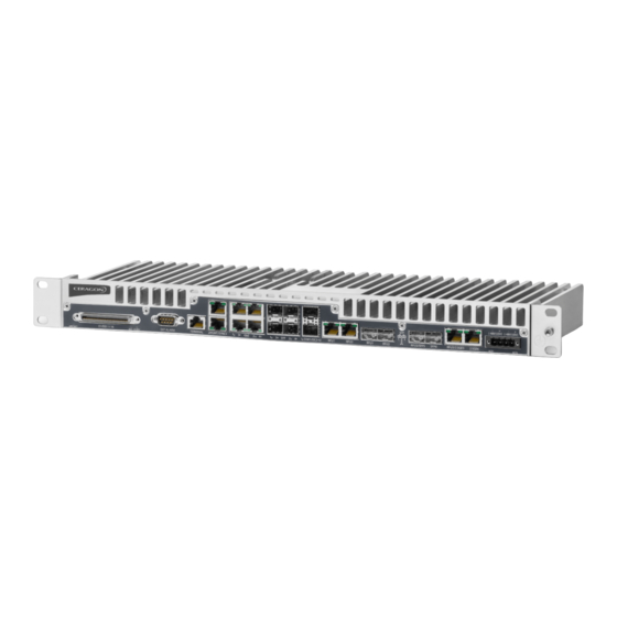
Installation Guide for FibeAir IP-20F FibeAir IP-20F Hardware Overview FibeAir IP-20F is a compact unit that fits in a single rack unit, with a passive cooling system that eliminates the need for fans. An IP-20F system consists of an IP-20F indoor unit (IDU) and up to three radio frequency units (RFUs). -
Page 12: Ethernet Traffic Interfaces
Installation Guide for FibeAir IP-20F Ethernet Traffic Interfaces The front panel of the FibeAir IP-20F contains 4 x GbE combo interfaces (electrical or optical) for Ethernet traffic. These interfaces are numbered as shown in Figure 2. Figure 2: GbE Combo Interface Numbering... -
Page 13: Ethernet Management Interfaces
Installation Guide for FibeAir IP-20F Ethernet Management Interfaces FibeAir IP-20F contains two FE management interfaces, which connect to a single RJ-45 physical connector on the front panel. The RJ-45 connector is the upper RJ-45 interface in a pair of interfaces labeled MGMT/SYNC. -
Page 14: E1/Ds1 Interface
Installation Guide for FibeAir IP-20F E1/DS1 Interface FibeAir IP-20F includes an MDR69 connector in which 16 E1 interfaces are available (ports 1 through 16). Page 14 of 63 Ceragon Proprietary and Confidential... -
Page 15: Stm-1/Oc-3 Interfaces
Installation Guide for FibeAir IP-20F STM-1/OC-3 Interfaces The IP-20F includes two ch-STM-1/OC-3 ports, which can be used as a 1+1 STM-1/OC-3 protection configuration. The STM-1/OC-3 port provides an interface for up to 63 E1 or 84 DS1 lines inside a standard channelized STM-1 or OC-3 signal. Each E1/DS1 line is transported by a VC-12 container, which behaves like a regular line interface. -
Page 16: Radio Interfaces
Installation Guide for FibeAir IP-20F Radio Interfaces FibeAir IP-20F includes two combo radio interfaces (RJ-45 or SFP, RFU1 and RFU2). A third interface can also be used as a combo radio interface (RJ-45 or SFP, RFU3). Note: For some RFUs, PoE power can be supplied directly from the IDU via an RJ-45 radio interface. -
Page 17: Power Interfaces
Installation Guide for FibeAir IP-20F Power Interfaces FibeAir IP-20F receives an external supply of -48V current via a dual-feed power interface, which can be connected to two separate power sources for power redundancy. The IP-20F monitors the power supply for under-voltage and includes reverse polarity protection, so that if the positive (+) and negative (-) inputs are mixed up, the system remains shut down. -
Page 18: Synchronization Interface
Installation Guide for FibeAir IP-20F Synchronization Interface FibeAir IP-20F includes an RJ-45 synchronization interface for T3 clock input and T4 clock output. The interface is the lower RJ-45 interface in a pair of interfaces labeled MGMT/SYNC. Page 18 of 63... -
Page 19: Terminal Interface
Installation Guide for FibeAir IP-20F Terminal Interface FibeAir IP-20F includes an RJ-45 terminal interface (RS-232). A local craft terminal can be connected to the terminal interface for local CLI management of the unit. Page 19 of 63 Ceragon Proprietary and Confidential... -
Page 20: External Alarms
Installation Guide for FibeAir IP-20F External Alarms IP-20F includes a DB9 dry contact external alarms interface. The external alarms interface supports five input alarms and a single output alarm. The input alarms are configurable according to: 1 Intermediate 2 Critical... -
Page 21: Storage Memory Card
1.10 Storage Memory Card Each FibeAir IP-20F unit includes a Storage Memory card (SM card). The SM card holds the configuration and software for the IDU. The SM-Card is embedded in the SM-Card plastic cover that is located under the SM-card aluminum cover. In the event of IDU replacement, re-using the existing SM card cover is necessary to ensure that the unit’s... -
Page 22: Preparing For Installation
Installation Guide for FibeAir IP-20F Preparing for Installation This section provides instructions for transporting, inspecting, and unpacking the equipment for an IP-20F system prior to installation. Page 22 of 63 Ceragon Proprietary and Confidential... -
Page 23: Transportation/Storage
Installation Guide for FibeAir IP-20F Transportation/Storage The equipment cases are prepared for shipment by air, truck, railway and sea, suitable for handling by forklift trucks and slings. The cargo must be kept dry during transport and storage. For sea-transport, deck-side shipment is not permitted. Carrier-owned cargo containers should be used. -
Page 24: Inspection
Check the packing lists and ensure that correct parts numbers quantities of goods have arrived. Inspect for any damage on the cases and equipment. Report any damage or discrepancy to a Ceragon representative, by e-mail or fax. Page 24 of 63 Ceragon Proprietary and Confidential... -
Page 25: Unpacking Equipment At The Site
To avoid malfunctioning or personnel injuries, equipment or accessories/kits/plug-in unit installation, requires qualified and trained personnel. Changes or modifications not expressly approved by Ceragon Networks could void the user's authority to operate the equipment Where special cables, shields, adapters and grounding kits are supplied or described in this manual, these items must be used, to comply with the relevant regulations. -
Page 26: Installing The Ip-20F Idu
Installation Guide for FibeAir IP-20F Installing the IP-20F IDU This section provides instructions for installing a FibeAir IP-20F IDU. Figure 6: IDU (Full Configuration) Page 26 of 63 Ceragon Proprietary and Confidential... -
Page 27: Kits Required To Perform The Installation
Installation Guide for FibeAir IP-20F Kits required to perform the installation Description Quantity IP-20F chassis 19" rack / sub-rack SM-Card Cover Page 27 of 63 Ceragon Proprietary and Confidential... -
Page 28: Tools
Installation Guide for FibeAir IP-20F Tools • Philips screwdriver Flat screwdriver • Page 28 of 63 Ceragon Proprietary and Confidential... -
Page 29: Installing The Ip-20F Idu In The Rack (19")
Installation Guide for FibeAir IP-20F Installing the IP-20F IDU in the Rack (19") 1 Insert and hold the IP-20F IDU in the rack, as shown in the following figures. Use four screws (not supplied with the installation kit) to fasten the IDU to the rack. -
Page 30: Grounding The Ip-20F
Installation Guide for FibeAir IP-20F Grounding the IP-20F Note: The unit must be grounded to the main rack grounding. If the grounding cable is 2 meters or less, the cable must have a thickness of at least 12 AWG. If the grounding cable is longer than 2 meters, a 6 AWG cable is required. -
Page 31: Replacing An Ip-20F Idu Or Sm-Card
Installation Guide for FibeAir IP-20F Replacing an IP-20F IDU or SM-Card If you should need to replace the IP-20F IDU, you must first remove the SM-Card Cover so that you can insert it into the new IDU. The SM-Card holds the configuration and software for the IDU. The SM-Card is embedded in the SM-Card plastic cover that is located under the SM-card aluminum cover. - Page 32 Installation Guide for FibeAir IP-20F 4 In the new IDU or, if you are upgrading the SM-Card, the old IDU, make sure that there is no foreign matter blocking the sockets in the opening where the SM-Card is installed. 5 Gently place the SM-Card in its place and tighten the 2 screws.
-
Page 33: Connecting The Power Cable
Installation Guide for FibeAir IP-20F Connecting the Power Cable Important! Before connecting the power supply to the IP-20F unit, you must verify that the positive pole in the external power supply is grounded! Power supply grounding should be in according with the... -
Page 34: Figure 8: Correct Wiring Of Power Connector
Installation Guide for FibeAir IP-20F FibeAir IP-20F utilizes a dual-feed power interface, which can be connected to two separate power supplies for power redundancy. A power cable connector is included with the IP-20F unit. The following power cables are available for use with an IP-20F unit:... -
Page 35: Figure 9: Connecting The Power Cable
Installation Guide for FibeAir IP-20F 4 Insert the wires into the connector. 5 Secure the wires in the connector with the screws. 6 Plug the connector into the IP-20F power interface and tighten the two screws on the sides of the connector to secure the connector. -
Page 36: Power Supply Notes
Installation Guide for FibeAir IP-20F Power Supply Notes Page 36 of 63 Ceragon Proprietary and Confidential... -
Page 37: Power Supply Notes
Installation Guide for FibeAir IP-20F Power Supply Notes When selecting a power source, the following must be considered: Voltage range: -40 VDC to -60 VDC. • • Recommended: Availability of a UPS (Uninterrupted Power Source), battery backup, and emergency power generator. -
Page 38: Idu-Rfu Cable Connection
DC power required for the RFU. For configuration instructions, refer to the User Guide for FibeAir IP-20F, IP-20G, and IP-20GX. For an RFU-D, RFU-E, or RFU-S connecting to an optical RFU interface, and for an RFU- D-HP connecting to either an electrical or an optical RFU interface, an external DC power cable is required to supply power to the RFU. -
Page 39: Performing Initial Configuration
Installation Guide for FibeAir IP-20F Performing Initial Configuration This section describes how to establish a management connection with the IP-20F unit and lists the configuration steps that should be performed in order to enable basic radio connectivity. For detailed configuration instructions, refer to the User Guide for FibeAir IP-20F, IP-20G, and IP-20GX. -
Page 40: Establishing A Connection
7.1.2 Connecting to the Unit with a LAN Connection FibeAir IP-20F contains two FE management interfaces, which connect to a single RJ-45 physical connector on the front panel (MGMT). For details on which type of cable to use to utilize either one or both management interfaces, refer to Management Interface Cable Options on page 13. - Page 41 The chassis IP address, as well as password, should be changed before the system is set in operation. For more information on these procedures, refer to the User Guide for FibeAir IP-20F, IP-20G, and IP-20GX. 1 Select Control Panel> All Control Panel Items >Network and Sharing Center.
-
Page 42: Logging On
Installation Guide for FibeAir IP-20F Logging On 1 Open an Internet browser (Internet Explorer or Mozilla Firefox). 2 Type in the default IP address "192.168.1.1" in the Address Bar. Figure 12: Login Window 3 Enter the following values: User Name: admin Password: admin 4 Click Apply. -
Page 43: Changing Your Password
In addition to the Admin password, there is an additional password protected user account, “root user”, which is configured in the system. The root user password and instructions for changing this password are available from Ceragon Customer Support. It is strongly recommended to change this password. -
Page 44: Configuration
In addition to setting the IP addresses, the following configuration steps should be performed in order to establish basic connectivity. For a detailed description of these procedures, refer to the User Guide for FibeAir IP-20F, IP-20G, and IP-20GX. • Enable the Radio Interfaces •... -
Page 45: Applying A Pre-Defined Configuration File
45 with PoE, you must do so manually after applying the pre-defined configuration file. See IDU-RFU Cable Connection on page 38. For configuration instructions, see Configuring the IDU-RFU Connection (IP-20F only) in the User Guide for FibeAir IP-20F, IP-20G, and IP-20GX. -
Page 46: Figure 15: Quick Configuration - From File Page - Configuration File Loaded
Installation Guide for FibeAir IP-20F 2 Click Browse, and select the configuration file for your unit. Figure 15: Quick Configuration – From File Page – Configuration File Loaded 3 In the Device List field, select the IP-20 unit you are configuring. -
Page 47: Specifications
Installation Guide for FibeAir IP-20F Specifications Page 47 of 63 Ceragon Proprietary and Confidential... -
Page 48: Environmental Specifications For Idu
Installation Guide for FibeAir IP-20F Environmental Specifications for IDU • Operating: ETSI EN 300 019-1-3 Class 3.2 Temperature: • -5C (23F) to 55C (131F) – Temperature range for continuous operating temperature with high reliability. -25C (-13F) to 65C (149F) – Temperature range for exceptional temperatures, tested successfully, with limited margins. -
Page 49: Environmental Specifications For Rfu
Installation Guide for FibeAir IP-20F Environmental Specifications for RFU • Operating: ETSI EN 300 019-1-4 Class 4.1 • Temperature: -33C (-27F) to +55C (131F) – Temperature range for continuous operating temperature with high reliability: -45C (-49F) to +60C (140F) – Temperature range for exceptional temperatures;... -
Page 50: Mechanical Specifications
Installation Guide for FibeAir IP-20F Mechanical Specifications Table 2: IDU Mechanical Specifications IDU Dimensions Height: 44 mm Width: 482 mm Depth: 165 mm Weight: 2.4 kg IDU-RFU Connection An RFU-S, RFU-E, RFU-D, and RFU-D-HP can be connected to an IP-20F IDU via a standard CAT-5e or CAT-6 cable, with RJ-45 connectors on the RFU and one of the RJ-45 RFU interfaces on the IP-20F. -
Page 51: Power Consumption Specifications
Installation Guide for FibeAir IP-20F Power Consumption Specifications The following table shows the maximum power consumption for IP-20F IDU and supported RFUs. The maximum power consumption for the entire system is the sum of the IDU and the RFUs connecting to it. -
Page 52: Acceptance & Commissioning Procedures
The purpose of this procedure is to verify correct installation and operation of the installed link and the interoperability with customer end equipment. Ceragon's Acceptance and Commissioning procedure includes the following stages: • Site Acceptance Procedure Commissioning of radio link •... -
Page 53: Site Acceptance Procedure
Installation Guide for FibeAir IP-20F Site Acceptance Procedure The purpose of the following procedures is to verify that all installation requirements were noted and checked. Following this procedure will ensure proper, long-lasting, and safe operation of the product. The checklist below summarizes the installation requirements of the site. - Page 54 Installation Guide for FibeAir IP-20F Antenna type (model and size): Antenna is securely fixed to mount Antenna is grounded as per site specifications Antenna sway braces are installed correctly (where applicable) Antenna Radome is securely fitted (where applicable) Water drain plugs are fitted and removed, as appropriate...
- Page 55 Installation Guide for FibeAir IP-20F Overall cable length: Cable type: N-Type connectors assembled properly on the cable Cable connected securely to RFU and IDU Cable connector is weather-proofed (sealed) at the RFU At the RFU, cable has a service/drip loop to prevent moisture from entering...
- Page 56 Installation Guide for FibeAir IP-20F IDU is securely mounted to the rack IDU is located in a properly ventilated environment IDU fans are functional and air flow to the fans is not disrupted IDU and rack are grounded as per site specifications...
- Page 57 Installation Guide for FibeAir IP-20F Name: Title: Site accepted by: Company: Signature: Date: Name: Title: Site approved by: Company: Signature: Date: Page 57 of 63 Ceragon Proprietary and Confidential...
-
Page 58: Site Acceptance Checklist Notes
Installation Guide for FibeAir IP-20F Site Acceptance Checklist Notes The following notes provide important additional information about the Site Acceptance Checklist. 1 Antenna Mounting Mounting pole is of sufficient height to clear local obstructions, such as • parapets, window cleaning gantries, and lift housings. - Page 59 Installation Guide for FibeAir IP-20F 4 Indoor Unit The main traffic connections are correctly terminated and crimped as per • cable and connector manufacturer instructions. All fiber optic patch leads should be routed carefully and efficiently, using conduits to prevent damage to the cables.
-
Page 60: Radio Link Commissioning Procedure
• remote end (or connect second analyzer). Run Packet Loss test for at least one hour (load rate as per Ceragon's specifications for the chosen MRMC). Connect Ethernet Packet Analyzer to the FE port. Use physical loop at remote •... -
Page 61: Ip-20 Commissioning Log
Maintaining the Commissioning Log is important for tracking your installations, and to provide essential data for Ceragon Networks. Upon completing the Commissioning Log, send the log to Ceragon support center at support@ceragon.com. IP-20 LINK COMMISSIONING LOG 1. - Page 62 Installation Guide for FibeAir IP-20F RFU model: RFU p/n: RFU s/n: RFU SW: IDU model: IDU p/n: IDU s/n: IDU SW: Tx frequency (MHz): Rx frequency (MHz): Link ID: Tx power (dBm): ATPC on/off: ATPC ref level: RFU Polarization: 3. ANTENNA AND RFU MOUNT...
- Page 63 Installation Guide for FibeAir IP-20F Line loopback: Pass Pass RFU loopback: Pass Pass Radio BER: Pass Pass FE test: Pass Pass GbE test: Pass Pass 6. MANAGEMENT Site 1 Site 2 CONFIGURATION Eth IP Address: Eth IP mask: Default router: In-band VLAN 7.
Need help?
Do you have a question about the FibeAir IP-20F and is the answer not in the manual?
Questions and answers