Ceragon FibeAir IP-20G Technical Description
Hide thumbs
Also See for FibeAir IP-20G:
- Installation manual (36 pages) ,
- Installation manual (49 pages) ,
- User manual (20 pages)

Subscribe to Our Youtube Channel
Related Manuals for Ceragon FibeAir IP-20G


Summary of Contents for Ceragon FibeAir IP-20G
- Page 1 ETSI Version ® FibeAir IP-20G Technical Description November 2014 Release: 7.9 Document Revision A.05 Copyright © 2014 by Ceragon Networks Ltd. All rights reserved.
- Page 2 Technical Description Notice This document contains information that is proprietary to Ceragon Networks Ltd. No part of this publication may be reproduced, modified, or distributed without prior written authorization of Ceragon Networks Ltd. This document is provided as is, without warranty of any kind.
-
Page 3: Table Of Contents
4.4.1 Main Features of 1500HP/RFU-HP ................49 4.4.2 1500HP/RFU-HP Functional Block Diagram and Concept of Operation ..... 51 4.4.3 1500HP/RFU-HP Comparison Table ................53 4.4.4 1500HP/RFU-HP System Configurations ..............53 4.4.5 Space Diversity with IF Combining ................54 Ceragon Proprietary and Confidential Page 3 of 266... - Page 4 6.5.1 Native TDM Trails ...................... 186 6.5.2 TDM Pseudowire ......................190 6.5.3 TDM Reference Solutions ..................196 7. FibeAir IP-20G Management ................ 198 Management Overview ....................199 Automatic Network Topology Discovery with LLDP Protocol ........200 Ceragon Proprietary and Confidential...
- Page 5 7.13 NTP Support ......................209 7.14 UTC Support ......................209 7.15 System Security Features ..................210 7.15.1 Ceragon’s Layered Security Concept ................ 210 7.15.2 Defenses in Management Communication Channels ..........211 7.15.3 Defenses in User and System Authentication Procedures ........212 7.15.4 Secure Communication Channels ................
- Page 6 9.13.2 1500HP/RFU-HP Antenna Connection ..............264 9.14 Waveguide Specifications ..................265 9.14.1 RFU-C Waveguide Specifications ................265 9.14.2 1500HP/RFU-HP Waveguide Specifications ............. 265 9.15 Power Input Specifications ..................266 9.16 Power Consumption Specifications ................266 Ceragon Proprietary and Confidential Page 6 of 266...
- Page 7 Header De-Duplication Potential Throughput Savings per Layer ..... 70 Propagation Delay with and without Frame Cut-Through ......... 73 Frame Cut-Through....................74 Frame Cut-Through Operation ................74 Adaptive Coding and Modulation with 10 Working Points ........ 77 Ceragon Proprietary and Confidential Page 7 of 266...
- Page 8 Mobile Backhaul Reference Model ..............104 Packet Service Core Building Blocks ............... 104 IP-20G Services Model ..................108 IP-20G Services Core ..................109 IP-20G Services Flow ..................110 Point-to-Point Service ..................111 Ceragon Proprietary and Confidential Page 8 of 266...
- Page 9 IP-20G End-to-End Service Management ............170 SOAM Maintenance Entities (Example) ............171 Ethernet Line Interface Loopback – Application Examples ......172 Precision Timing Protocol (PTP) Synchronization .......... 175 Synchronous Ethernet (SyncE)................. 176 Synchronization Configuration ................. 178 Ceragon Proprietary and Confidential Page 9 of 266...
- Page 10 Aggregation ....................196 TDM Pseudowire Interoperability with Optical SDH Equipment ..... 196 TDM Pseudowire Interoperability with Third-Party Packet Aggregation Equipment ..................... 197 Integrated IP-20G Management Tools .............. 199 Security Solution Architecture Concept ............210 Ceragon Proprietary and Confidential Page 10 of 266...
- Page 11 MPLS EXP Default Mapping to CoS and Color ..........140 QoS Priority Profile Example ................155 WFQ Profile Example ..................157 802.1q UP Marking Table (C-VLAN) ..............159 802.1ad UP Marking Table (S-VLAN) ..............160 Ceragon Proprietary and Confidential Page 11 of 266...
- Page 12 RFU-C Mediation Device Losses ............... 254 IDU Mechanical Specifications ................. 262 RFU-C Mechanical Specifications ..............262 1500HP/RFUHP Mechanical Specifications ............262 RFU-C – Waveguide Flanges ................265 1500HP/RFU-HP – Waveguide Flanges ............. 265 Ceragon Proprietary and Confidential Page 12 of 266...
- Page 13 This manual is intended for use by Ceragon customers, potential customers, and business partners. The purpose of this manual is to provide basic information about the FibeAir IP-20G for use in system planning, and determining which FibeAir IP-20G configuration is best suited for a specific network.
-
Page 14: Synonyms And Acronyms
Ethernet Virtual Private Line Ethernet Virtual Connection FTP (SFTP) File Transfer Protocol (Secured File Transfer Protocol) Gigabit Ethernet Greenwich Mean Time Hot Standby HTTP (HTTPS) Hypertext Transfer Protocol (Secured HTTP) Indoor Controller Indoor unit Ceragon Proprietary and Confidential Page 14 of 266... - Page 15 Precision Timing-Protocol Pseudowire Quality of-Experience Quality of Service RBAC Role-Based Access Control Reverse Defect Indication Radio Frequency Unit RMON Ethernet Statistics Received Signal Level RSTP Rapid Spanning Tree Protocol Service Access Point Ceragon Proprietary and Confidential Page 15 of 266...
- Page 16 Type of Service User Network Interface Coordinated Universal Time Virtual Containers Web EMS Web-Based Element Management System Wave guide Weighted Fair Queue WRED Weighted Random Early Detection XPIC Cross Polarization Interference Cancellation Ceragon Proprietary and Confidential Page 16 of 266...
-
Page 17: Introduction
FibeAir® IP-20G Technical Description Introduction This chapter provides an overview of the FibeAir IP-20G, Ceragon’s high- performance edge node product. IP-20G is specially designed for edge/tail sites, and features a small footprint, high density, and a high degree of availability. -
Page 18: Product Overview
2x FE electrical interfaces (RJ-45) External alarms interface FibeAir IP-20G is based on a passive cooling design that does not require fans, for improved operational efficiency. IP-20G enables operators to maximize QoE with an improved customer experience by providing TCP-friendly backhaul. The system provides support for emerging services, standards, and networking protocols (future proof). -
Page 19: Ip-20G Radio Options
(“green mode”) that enables the microwave system to automatically detect when link conditions allow it to use less power. 1500HP/RFU-HP provide a range of modulations from QPSK to 1024 QAM. For additional information: 1500HP/RFU-HP Ceragon Proprietary and Confidential Page 19 of 266... -
Page 20: Ip-20G Highlights
FibeAir® IP-20G Technical Description IP-20G Highlights 2.1.2 The following are some of the highlights of FibeAir IP-20G. Optimized tail/edge solution supporting seamless integration of radio (L1) and end-to-end Carrier Ethernet transport/services (L2) functionality Rich packet processing feature set for support of engineered end-to-end Carrier Ethernet services with strict SLA ... -
Page 21: Reference Configurations
IP-20 product portfolio, with their common CeraOS software platform, are utilized as the building blocks of a heterogeneous network (HetNet). IP-20 Platform Reference Topology Ceragon Proprietary and Confidential Page 21 of 266... -
Page 22: Dual Modem Activation
2+0 XPIC or 1+1 HSB configurations (lower right in the figure). Reference Configuration – Dual Modem Activation 16xE1s 6xGE/FE (Optional) Second Modem Activation 2+0 XPIC/1+1 HSB 16xE1s 6xGE/FE (Optional) 16xE1s 6xGE/FE (Optional) Ceragon Proprietary and Confidential Page 22 of 266... -
Page 23: Idu Cascading With Dual Modems
This connection utilizes the GbE1 dual mode electrical/cascading port, leaving ten Ethernet ports available for other traffic. Reference Configuration – IDU Cascading with Dual Modems Second Modem Activation IP-20G IDU 16xE1s 6xGE/FE Cascading (Optional) Second Modem Activation 32xE1s 10xGE/FE (Optional) Ceragon Proprietary and Confidential Page 23 of 266... -
Page 24: Chained Network
The fourth node consists of a dual-modem IP-20G unit connected to the third node via a 1+1 or a 2+0 XPIC link. Reference Configuration – Chained Network 16xE1s 6xGE/FE 1+1/2+0 XPIC (Optional) 16xE1s 6xGE/FE (Optional) 32xE1s 10xGE/FE (Optional) 16xE1s 6xGE/FE (Optional) Ceragon Proprietary and Confidential Page 24 of 266... -
Page 25: Ring With Spur
MSTP and G.8032 network resiliency protocols for ring protection. Reference Configuration – Ring with Spur Ring Protection 16xE1s 6xGE/FE 16xE1s 6xGE/FE (Optional) (Optional) 16xE1s 6xGE/FE (Optional) 32xE1s 10xGE/FE (Optional) Ceragon Proprietary and Confidential Page 25 of 266... -
Page 26: Aggregation/Pop Site
Reference Configuration – Aggregation/POP Site GE/FE STM-1s (Optional) Ring E1s (Optional) Protection 16xE1s 6xGE/FE (Optional) 16xE1s 6xGE/FE (Optional) 16xE1s 6xGE/FE (Optional) 32xE1s 10xGE/FE (Optional) 16xE1s 6xGE/FE (Optional) Ceragon Proprietary and Confidential Page 26 of 266... -
Page 27: New Features In Version T7.9
Interfaces MSTP support for mesh topologies and interoperability with Multiple Spanning Tree Protocol Operation > Web EMS Configuration > legacy IP-10 platforms in RSTP mode. (MSTP) on page 167 Ethernet > MSTP Ceragon Proprietary and Confidential Page 27 of 266... - Page 28 Operation > CLI Configuration > Platform Configuration > Configuring Management > Configuring and Displaying Unit Parameters Support Web EMS configuration for unmuting remote radio Operation > Web EMS Configuration > Radio > Remote Radio Ceragon Proprietary and Confidential Page 28 of 266...
-
Page 29: Idu Hardware Description
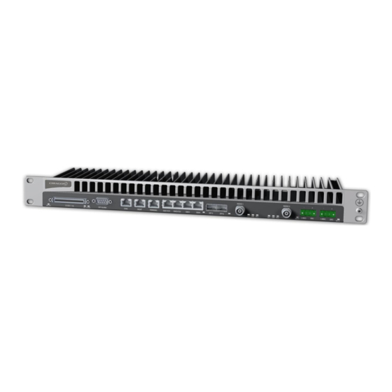
FibeAir® IP-20G Technical Description IDU Hardware Description This chapter describes the FibeAir IP-20G indoor unit and its interfaces, including a description of the available hardware assembly options. This chapter includes: Hardware Architecture Front Panel Description Ethernet Traffic Interfaces ... -
Page 30: Hardware Architecture
Technical Description Hardware Architecture FibeAir IP-20G is a compact unit that fits in a single rack unit, with a passive cooling system that eliminates the need for fans. An IP-20G system consists of an IP-20G indoor unit (IDU) and one or two radio frequency units (RFUs). A coaxial cable connects the IDU to each RFU, transmits traffic and management data between the IDU and the RFU, and provides DC -48V power to the RFU. -
Page 31: Ip-20G Block Diagram
Ethernet TDM Interfaces (Optional) GE Traffic Interfaces Network Processor 16 x E1 TDM Pseudowire Services Services Framer Interface Processor Services GE/Cascading Interfaces Engine TDM Cross Connect Native TDM Services Multi-Carrier ABC Engine Ceragon Proprietary and Confidential Page 31 of 266... -
Page 32: Front Panel Description
Ethernet Traffic Interfaces Cascading Interfaces (RJ-45) 2 x GE Electrical Interfaces (RJ-45) Ethernet Traffic Interfaces 2 x GE Optical Interfaces (SFP) Ethernet Traffic Interfaces Radio Interfaces (TNC) Radio Interfaces Power Interfaces -48V Power Interfaces Ceragon Proprietary and Confidential Page 32 of 266... -
Page 33: Ethernet Traffic Interfaces
Related Topics: Physical Interfaces Ethernet Interface Specifications The front panel of the FibeAir IP-20G contains four electrical and two optical GE Ethernet traffic interfaces: 2 x GE dual mode electrical or cascading interfaces (RJ-45) – GbE1/CS1, GbE2/CS2 ... -
Page 34: Optical Ge Interface Led
Off – The interface is shut down or the signal is lost. Green – The interface is enabled and the link is operational. Blinking Green – The interface is transmitting and/or receiving traffic. Optical GE Interface LED Ceragon Proprietary and Confidential Page 34 of 266... -
Page 35: Ethernet Management Interfaces
Ethernet Management Interfaces Related Topics: Physical Interfaces Ethernet Interface Specifications FibeAir IP-20G contains two FE management interfaces, which connect to a single RJ-45 physical connector on the front panel (MGMT). Management Interface Pin Connections RJ-45 Connector Management Switch (female) -
Page 36: Management Fe Interface Leds
FibeAir® IP-20G Technical Description Management FE Interface LEDs Ceragon Proprietary and Confidential Page 36 of 266... -
Page 37: E1 Interface (Optional)
TDM Services E1 Interface Specifications Optionally, FibeAir IP-20G can be ordered with an MDR69 connector in which 16 E1 interfaces are available (ports 1 through 16). The E1 interface has the following LEDs ACT LED – Indicates whether the TDM card is working properly (Green) or if there is an error or a problem with the card’s functionality (Red). -
Page 38: Radio Interfaces
Technical Description Radio Interfaces FibeAir IP-20G includes one or two radio interfaces, depending on the hardware assembly option that was selected. Each radio interface uses a TNC connector type. Each radio interface is connected to an RFU via coaxial cable. -
Page 39: Radio Interface Leds
FibeAir® IP-20G Technical Description Radio Interface LEDs Ceragon Proprietary and Confidential Page 39 of 266... -
Page 40: Power Interfaces
FibeAir® IP-20G Technical Description Power Interfaces FibeAir IP-20G receives an external supply of -48V current via one or two power interfaces (the second power interface is optional for power redundancy). The IP-20G monitors the power supply for under-voltage and includes reverse polarity protection, so that if the positive (+) and negative (-) inputs are mixed up, the system remains shut down. -
Page 41: Synchronization Interface
FibeAir® IP-20G Technical Description Synchronization Interface FibeAir IP-20G includes an RJ-45 synchronization interface for T3 clock input and T4 clock output. The interface is labeled SYNC. The synchronization interface contains two LEDs, one on the upper left of the interface and one on the upper right of the interface, as follows: ... -
Page 42: Terminal Interface
FibeAir® IP-20G Technical Description Terminal Interface FibeAir IP-20G includes an RJ-45 terminal interface (RS-232). A local craft terminal can be connected to the terminal interface for local CLI management of the unit. Unit/ACT LED 3.10 A general ACT LED for the unit is located on the lower left of the IP-20G front panel. -
Page 43: External Alarms
The input alarms are configurable according to: 1 Intermediate 2 Critical 3 Major 4 Minor 5 Warning The output alarm is configured according to predefined categories. Ceragon Proprietary and Confidential Page 43 of 266... -
Page 44: Storage Memory Card
Storage Memory Card 3.12 Each FibeAir IP-20G unit includes a Storage Memory card (SM card). The SM card holds the configuration and software for the IDU. The SM card is embedded in the SM card cover. In the event of IDU replacement, re-using the existing SM card cover is necessary to ensure that the unit’s software and... -
Page 45: Rfu Hardware Description And Branching Options
IP-20G works with the following RFUs: Standard Power FibeAir RFU-C High Power FibeAir 1500HP FibeAir RFU-HP This chapter includes: RFU Overview RFU Selection Guide RFU-C 1500HP/RFU-HP Ceragon Proprietary and Confidential Page 45 of 266... -
Page 46: Rfu Overview
The antenna connection can be: Direct or remote mount using the same antenna type. Remote mount: standard flexible waveguide (frequency dependent) Remote mount configuration is not supported for 42 GHz. Ceragon Proprietary and Confidential Page 46 of 266... -
Page 47: Rfu Selection Guide
√ √ √ Modulation 512 to 1024 QAM √ √ RFU-HP does not support 56 MHz channels at 11 GHz. IFC at 40MHz is supported only for the 11GHz frequency band. Ceragon Proprietary and Confidential Page 47 of 266... -
Page 48: Rfu-C
For additional information: Specifications For details about supported modulation capabilities beyond 256 QAM using a standard RFU-C, contact your Ceragon representative. Remote mount configuration is not supported for 42 GHz. Ceragon Proprietary and Confidential Page 48 of 266... -
Page 49: 1500Hp/Rfu-Hp
1500 HP (11 GHz ) 40 MHz bandwidth does not support IF Combining. For this frequency, space diversity is only available via BBS. IP-20G support for 2048 QAM is planned for future release. Ceragon Proprietary and Confidential Page 49 of 266... - Page 50 RFU-HP) Tx Range (Manual/ATPC) – Up to 20 dB dynamic range ATPC (Automatic Tx Power Control) RF Channel Selection – Via EMS/NMS NEBS – Level 3 NEBS compliance Ceragon Proprietary and Confidential Page 50 of 266...
-
Page 51: 1500Hp/Rfu-Hp Functional Block Diagram And Concept Of Operation
DC / CTRL TXCO -48V Extention port chain RX Main 140MHz diplexer XPIC SW IF & controller Board RX Board Chassis XPIC source sharing \ RSL ind. (Ntype conn.) (TNC conn.) Ceragon Proprietary and Confidential Page 51 of 266... - Page 52 Each of these RFU types must be connected to an OCB (Outdoor Circulator Block) which serves as both a narrow diplexer and a mediation device to facilitate antenna connection. For additional information: 1500HP/RFU-HP OCBs Ceragon Proprietary and Confidential Page 52 of 266...
-
Page 53: 1500Hp/Rfu-Hp Comparison Table
The following configurations are applicable for Split-Mount or all indoor installations: 1500 HP (11 GHz ) 40 MHz bandwidth does not support IF Combining. For this frequency, space diversity is only available via BBS. Ceragon Proprietary and Confidential Page 53 of 266... -
Page 54: Space Diversity With If Combining
(horizontal) configuration, the OCB branching network is used. When using an All-Indoor vertical configuration, the ICB branching network is used. The main differences in branching concept between the OCB and the ICB relate to how the signals are circulated. Ceragon Proprietary and Confidential Page 54 of 266... -
Page 55: All-Indoor Vertical Branching
Routes the RF signal in the correct direction, through the filters and circulators. Enables RFU connection to the Main and Diversity antennas. FibeAir 1500HP and RFU-HP supports two types of OCBs: OCB (Older Type) OCB (Current Type) Ceragon Proprietary and Confidential Page 55 of 266... -
Page 56: Ld Ocb
Diversity port If the system is not configured for diversity, all the relevant ports on the OCB must be terminated using waveguide shorts. Unused Rx ports are terminated with a 50 ohm termination. Ceragon Proprietary and Confidential Page 56 of 266... -
Page 57: Ocb And Dcb Block Diagram
The S Bend connects the chained OCB (Outdoor Circulator Block) in N+1 /N+ 0 configurations. Pole Mount Kit The Pole Mount Kit can attach up to five OCBs and the RFUs to the pole. The kit enables fast and easy pole mount installation. Ceragon Proprietary and Confidential Page 57 of 266... -
Page 58: Ocb Component Summary
Open ports on the OCBs are terminated with waveguide terminations. Detailed upgrade procedure documents are available for specific configurations. Please note that legacy OCBs can be upgraded and cascaded with the new OCB. Ceragon Proprietary and Confidential Page 58 of 266... -
Page 59: 1500Hp/Rfu-Hp Models And Part Numbers
Non Space Diversity (1Rx) (6, 7, 8GHz) 15OCBf-xxxy-ZZ-H/L 11GHz Non Space Diversity (1Rx) 15OCB11w-xxxy-ZZ-H/L 11GHz OCB is a wide BW OCB which supports up to 40MHz, while the other OCBs (6L, 6H, 7, 8GHz) support up to 30MHz. Ceragon Proprietary and Confidential Page 59 of 266... -
Page 60: Ocb Part Numbers For All Indoor Compact
Description and Remarks Marketing Model 6L,6H,7,8,11 000-999 [MHz] TRS in MHz A…Z Ceragon TRS block designation Examples: Designation of the channels the OCB is covering 1W3 – “Wide” filters covering channels 1-3 03 – Only channel 03, 28MHz channel 3-5 – 56MHz “Narrow” filters allowing concatenation using OCBs covering channels 3 and 4. -
Page 61: Activation Keys
A 1+1 HSB configuration requires the same set of per-carrier activation keys for both the active and the protected carriers. This chapter includes: Working with Activation Keys Demo Mode Activation Key-Enabled Features Ceragon Proprietary and Confidential Page 61 of 266... -
Page 62: Working With Activation Keys
FibeAir® IP-20G Technical Description Working with Activation Keys Ceragon provides a web-based system for managing activation keys. This system enables authorized users to generate activation keys, which are generated per IDU serial number. In order to upgrade an activation key, the activation key must be entered into the IP-20G. - Page 63 Quality of Service (QoS) required to add service-bundles with dedicated queues to interfaces. Without this activation key, only the default eight queues per port are supported. H-QoS support is planned for future release. Ceragon Proprietary and Confidential Page 63 of 266...
-
Page 64: Capacity Activation Key Levels
IP-20-SL-Capacity-300M IP-20 SL - Capacity 300M, per carrier Support for HTTPS and RADIUS is planned for future release. FM support is planned for future release. PM support is planned for future release. Ceragon Proprietary and Confidential Page 64 of 266... -
Page 65: Cet Node Activation Key Levels
Enables CET with up to 8 services/EVCs. IP-20-SL-Agg-Lvl-1-CET-Node Enables CET with up to 64 services/EVCs. IP-20-SL-Agg-Lvl-2-CET-Node Enables CET with up to 1024 services/EVCs. IP-20-SL-Upg-Edge/Agg-Lvl-1 Upgrades from "Edge-CET-Node" to "Agg-Lvl-1-CET-Node". IP-20-SL-Upg-Agg-Lvl-1/Lvl-2 Upgrades from "Edge-CET-Node" to "Agg-Lvl-2-CET-Node". Ceragon Proprietary and Confidential Page 65 of 266... -
Page 66: Feature Description
This chapter describes the main IP-20G features. The feature descriptions are divided into the categories listed below. This chapter includes: Innovative Techniques to Boost Capacity and Reduce Latency Radio Features Ethernet Features Synchronization TDM Services Ceragon Proprietary and Confidential Page 66 of 266... -
Page 67: Innovative Techniques To Boost Capacity And Reduce Latency
Note: Header De-Duplication is planned for future release. IP-20G also utilizes established Ceragon technology to provide low latency representing a 50% latency reduction for Ethernet services compared to the industry benchmark for wireless backhaul. Another of Ceragon’s innovative features is Frame Cut-Through, which provides unique delay and delay-variation control for delay-sensitive services. -
Page 68: Capacity Summary
RFU, and up to 1 Gbps with Header De-Duplication. Modulations – QPSK to 2048 QAM For additional information: Radio Capacity Specifications IP-20G support for 2048 QAM is planned for future release. Ceragon Proprietary and Confidential Page 68 of 266... -
Page 69: Header De-Duplication
Tunnel layer for packets carrying GTP or GRE frames. Tunnel-Layer3 – Header De-Duplication operates on Layer 2, Layer 3, and on the Tunnel and T-3 layers for packets carrying GTP or GRE frames. Ceragon Proprietary and Confidential Page 69 of 266... -
Page 70: Header De-Duplication Potential Throughput Savings Per Layer
End User Depending on the packet size and network topology, Header De-Duplication can increase capacity by up to: 50% (256 byte packets) 25% (512 byte packets) 8% (1518 byte packets) Ceragon Proprietary and Confidential Page 70 of 266... - Page 71 Header De-Duplication settings. By monitoring the effectiveness of the Header De- Duplication settings, the operator can adjust these settings to ensure that the network achieves the highest possible effective throughput. Ceragon Proprietary and Confidential Page 71 of 266...
-
Page 72: Latency
IP-20G’s ability to meet the stringent latency requirements for LTE systems provides the key to expanded broadband wireless services: Longer radio chains Larger radio rings Shorter recovery times More capacity Easing of Broadband Wireless Access (BWA) limitations Ceragon Proprietary and Confidential Page 72 of 266... -
Page 73: Frame Cut-Through
Improved QoE for VoIP and other streaming applications. Expedited delivery of critical control frames. Propagation Delay with and without Frame Cut-Through With Frame Cut-Through Without Frame Cut- Through Max Delay Max Delay Propagation Delay Ceragon Proprietary and Confidential Page 73 of 266... -
Page 74: Frame Cut-Through Operation
Frame Cut-Through Frame 5 Start When enabled, Frame Cut-Through applies to all high priority frames, i.e., all frames that are classified to a CoS queue with 4 (highest) priority. Frame Cut-Through Operation Ceragon Proprietary and Confidential Page 74 of 266... -
Page 75: Radio Features
Radio Features This chapter describes the main IP-20G radio features. Ceragon was the first to introduce hitless and errorless Adaptive Coding Modulation (ACM) to provide dynamic adjustment of the radio’s modulation from QPSK to 256 QAM. ACM shifts modulations instantaneously in response to changes in fading conditions. -
Page 76: Adaptive Coding Modulation (Acm)
Cross Polarization Interference Canceller (XPIC) Quality of Service (QoS) FibeAir IP-20G employs full-range dynamic ACM. IP-20G’s ACM mechanism copes with 90 dB per second fading in order to ensure high transmission quality. IP-20G’s ACM mechanism is designed to work with IP-20G’s QoS... -
Page 77: Adaptive Coding And Modulation With 10 Working Points
The selected profile is the only profile that will be valid, and the ACM engine will be forced to be OFF. Fixed mode can be chosen without an ACM activation key. Ceragon Proprietary and Confidential Page 77 of 266... - Page 78 RX Active unit’s ACM requests (only the active remote RX sends ACM request messages). In the RX direction, both the active and the standby carriers follow the remote Active TX profile (which is the only active transmitter). Ceragon Proprietary and Confidential Page 78 of 266...
-
Page 79: Cross Polarization Interference Canceller (Xpic)
For high-modulation schemes such as 1024 QAM, operating at a frequency of 28 GHz, an improvement factor of more than 20 dB is required so that cross-interference does not adversely affect performance. Ceragon Proprietary and Confidential Page 79 of 266... -
Page 80: Xpic Implementation
XPIC – Impact of Misalignments and Channel Degradation IP-20G’s XPIC reaches a BER of 10e-6 at a high level of co-channel interference (modulation-dependent). For exact figures, contact your Ceragon representative. Ceragon Proprietary and Confidential Page 80 of 266... - Page 81 The script must support XPIC If any of these conditions is not met, an alarm will alert the user. In addition, events will inform the user which conditions are not met. Ceragon Proprietary and Confidential Page 81 of 266...
-
Page 82: 1+1 Hsb Radio Protection
Revertive HSB protection ensures that the radios with no loss are active as long as no failures are present, resulting in the best possible link budget (0 dB loss). Ceragon Proprietary and Confidential Page 82 of 266... -
Page 83: Path Loss On Secondary Path Of 1+1 Hsb Protection Link
The following events trigger switchover for 1+1 HSB protection according to their priority, with the highest priority triggers listed first. 1 Hardware module missing 2 Lockout 3 Force switch 4 Traffic failures 5 Manual switch Ceragon Proprietary and Confidential Page 83 of 266... -
Page 84: Atpc
ATPC is frequently used as a means to mitigate frequency interference issues with the environment, thus allowing new radio links to be easily coordinated in frequency congested areas. Ceragon Proprietary and Confidential Page 84 of 266... -
Page 85: Multi-Carrier Abc
The following diagram illustrates the Multi-Carrier ABC traffic flow. Multi-Carrier ABC Traffic Flow Carrier 1 Carrier 1 Carrier 2 Carrier 2 Traffic Traffic Splitter Combiner Carrier 3 Carrier 3 Carrier 4 Carrier 4 Ceragon Proprietary and Confidential Page 85 of 266... - Page 86 Multi-Carrier ABC automatically adapts to capacity changes that result from changes in the current ACM profile. When an ACM profile change takes place on a specific carrier, Multi-Carrier ABC responds by changing the block size of that channel. Ceragon Proprietary and Confidential Page 86 of 266...
-
Page 87: Bbs Space Diversity
The Multi-Carrier ABC mechanism constantly monitors the signal quality of the main and diversity carrier, and selects the signal with the best quality. Switching between the main and diversity carriers is hitless. Ceragon Proprietary and Confidential Page 87 of 266... -
Page 88: 1+1 Bbs Space Diversity Configuration - Receiving Side
Technical Description 1+1 BBS Space Diversity Configuration – Receiving Side Radio & Note: IP-20G also supports Space Diversity by means of IF Combining. See Space Diversity with IF Combining on page 54. Ceragon Proprietary and Confidential Page 88 of 266... -
Page 89: Radio Utilization Pms
Over-Threshold Utilization (seconds). The threshold is defined as 0. Frame Error Rate – Measures the frame error rate (%), and used to generate Frame Error Rate PMs for every 15-minute interval. Ceragon Proprietary and Confidential Page 89 of 266... -
Page 90: Ethernet Features
Ethernet Services Overview IP-20G’s Ethernet Capabilities Supported Standards Ethernet Service Mode Ethernet Interfaces Quality of Service (QoS) Global Switch Configuration Automatic State Propagation Network Resiliency Ceragon Proprietary and Confidential Page 90 of 266... -
Page 91: Ethernet Services Overview
MEN, such as SDH/SONET, Ethernet, ATM, MPLS, and GFP. However, from the user’s perspective, the network connection at the user side of the UNI is only Ethernet. Ceragon Proprietary and Confidential Page 91 of 266... -
Page 92: Ethernet Virtual Connection (Evc)
Based on these characteristics, an EVC can be used to form a Layer 2 private line or Virtual Private Network (VPN). One or more VLANs can be mapped (bundled) to a single EVC. Ceragon Proprietary and Confidential Page 92 of 266... -
Page 93: Point To Point Evc
Roots, but not to other Leaves. Rooted Multipoint EVC In the IP-20G, an EVC is defined by either a VLAN or by Layer 1 connectivity (Pipe Mode). Ceragon Proprietary and Confidential Page 93 of 266... - Page 94 If the service frame fails to comply with both the CIR and the EIR defined in the bandwidth profile, it is marked Red and discarded. In the IP-20G, bandwidth profiles are constructed using a full standardized TrTCM policer mechanism. Ceragon Proprietary and Confidential Page 94 of 266...
-
Page 95: Mef Ethernet Services Definition Framework
IDs (CE-VLAN IDs) entering the service via the UNI are associated with a single EVC. Bundling refers to a UNI attribute in which more than one CE- VLAN ID can be associated with an EVC. Ceragon Proprietary and Confidential Page 95 of 266... -
Page 96: E-Line Service Type Using Point-To-Point Evc
UNI when the service frame is delivered (L1 service). A dedicated UNI (physical interface) is used for the service and service multiplexing is not allowed. All service frames are mapped Ceragon Proprietary and Confidential Page 96 of 266... -
Page 97: Epl Application Example
EVC while others may be sent to other EVCs. EVPL services can be used to replace Frame Relay and ATM L2 VPN services, in order to deliver higher bandwidth, end-to-end services. EVPL Application Example Ceragon Proprietary and Confidential Page 97 of 266... -
Page 98: E-Lan Service Type Using Multipoint-To-Multipoint Evc
UNI. E-LAN services can simplify the interconnection among a large number of sites, in comparison to hub/mesh topologies implemented using point-to- point networking technologies such as Frame Relay and ATM. Ceragon Proprietary and Confidential Page 98 of 266... -
Page 99: Adding A Site Using An E-Line Service
Adding a Site Using an E-LAN service The E-LAN service type can be used to create a broad range of services, such as private LAN and virtual private LAN services. Ceragon Proprietary and Confidential Page 99 of 266... -
Page 100: Mef Ethernet Private Lan Example
Layer 2 control protocols may or may not be provided. Service multiplexing is allowed on each UNI. A typical use case would be to provide Internet access a corporate VPN via one UNI. Ceragon Proprietary and Confidential Page 100 of 266... -
Page 101: Mef Ethernet Virtual Private Lan Example
In this scenario, each Leaf UNI can exchange data only with the Root UNIs. The Root UNIs can communicate with each other. Redundant access to the Root can also be provided, effectively allowing for enhanced service reliability and flexibility. Ceragon Proprietary and Confidential Page 101 of 266... -
Page 102: E-Tree Service Type Using Multiple Roots
EP-Tree services support CE-VLAN ID preservation. EP-Tree also supports CE-VLAN CoS preservation. EP-Tree requires dedication of the UNIs to the single EP-Tree service. The following figure provides an example of an EP-Tree service. MEF Ethernet Private Tree Example Ceragon Proprietary and Confidential Page 102 of 266... -
Page 103: Ethernet Virtual Private Tree Example
Network Controller/Gateway sites for all generations of mobile technologies. Mobile equipment and networks with ETH service layer functions can support MEF Carrier Ethernet services using the service attributes defined by the MEF. Ceragon Proprietary and Confidential Page 103 of 266... -
Page 104: Mobile Backhaul Reference Model
20G services core, which is structured around the building blocks shown in the figure below. IP-20G provides rich and secure packet backhaul services over any transport type with unified, simple, and error-free operation. Packet Service Core Building Blocks Ceragon Proprietary and Confidential Page 104 of 266... - Page 105 Superb service OAM (CFM, PM) Carrier-grade service resiliency (G.8032) E-Tree services are planned for future release. H-QoS support is planned for future release. CFM support is planned for future release. Ceragon Proprietary and Confidential Page 105 of 266...
-
Page 106: Ip-20G's Ethernet Capabilities
Enhanced <50msec network level resiliency (G.8032) for ring/mesh support E-Tree service support is planned for future release. Split horizon is planned for future release. LAG support is planned for future release. Ceragon Proprietary and Confidential Page 106 of 266... -
Page 107: Supported Standards
IP-20G is fully MEF-9 and MEF-14 certified for all Carrier Ethernet services. For a full list of standards and certifications supported by IP-20G, refer to the following section: Supported Ethernet Standards Ceragon Proprietary and Confidential Page 107 of 266... -
Page 108: Ethernet Service Model
The IP-20G services core provides for fully flexible C-VLAN and S-VLAN encapsulation, with a full range of classification, preservation, and translation options available. Service security and isolation is provided without limiting the C-VLAN reuse capabilities of different customers. Ceragon Proprietary and Confidential Page 108 of 266... -
Page 109: Ip-20G Services Core
IP-20G Services Core P2P Service Port 1 Port 4 Port 4 Port 5 Port 6 Multipoint Service Port 7 Port 2 Port 8 Port 3 Smart Pipe Service Port 4 Port 9 Ceragon Proprietary and Confidential Page 109 of 266... -
Page 110: Ip-20G Services Flow
Service Types IP-20G supports the following service types: Point-to-Point Service (P2P) MultiPoint Service (MP) Management Service Point-to-Multipoint Service (E-Tree) Note: E-Tree service support is planned for future release. Ceragon Proprietary and Confidential Page 110 of 266... - Page 111 If the destination MAC address is not known by the learning and forwarding mechanism, the arriving frame is flooded to all the other service points in the service except the ingress service point. Ceragon Proprietary and Confidential Page 111 of 266...
- Page 112 MAC forwarding table for the frame’s destination MAC address. If a match is found, the frame is forwarded to the service point associated with the MAC address. If not, the frame is flooded to all service points in the service. Ceragon Proprietary and Confidential Page 112 of 266...
-
Page 113: Ethernet Services Learning And Forwarding
They can also be used to manage third-party devices. Users can enable or disable these ports. Ceragon Proprietary and Confidential Page 113 of 266... -
Page 114: Management Service
NMS for topology management. EVC Description – The Ethernet Virtual Connection description. This parameter does not affect the network element’s behavior, but is used by the NMS for topology management. Ceragon Proprietary and Confidential Page 114 of 266... - Page 115 Instance (0-46, 4095) – The spanning tree instance ID to which the service belongs. The service can be a traffic engineering service (instance ID 4095) or can be managed by the xSTP engines of the network element. Ceragon Proprietary and Confidential Page 115 of 266...
-
Page 116: Management Service And Its Service Points
Service Access Point (SAP) Service Point – An SAP is equivalent to a UNI in MEF terminology and defines the connection of the user network with its access points. SAPs are used for Point-to-Point and Multipoint traffic services. Ceragon Proprietary and Confidential Page 116 of 266... -
Page 117: Saps And Snps
The following figure shows a Point-to-Point service with Pipe service points that create a Smart Pipe between Port 1 of the network element on the left and Port 2 of the network element on the right. Ceragon Proprietary and Confidential Page 117 of 266... -
Page 118: Pipe Service Points
Smart Pipe is also used, to provide connectivity between elements that require port-based connectivity. SAP, SNP and Pipe Service Points in a Microwave Network Fiber Aggregation Network Microwave Network PIPE PIPE Base Station Ceragon Proprietary and Confidential Page 118 of 266... -
Page 119: Service Point Types Per Service Type
SNPs can be used with the following Attached Interface Types: Dot1q – A single C VLAN is classified to the service point. S-Tag – A single S- VLAN is classified to the service point. Ceragon Proprietary and Confidential Page 119 of 266... -
Page 120: Service Point Types That Can Co-Exist On The Same Interface
SNP SP PIPE SP Only one Pipe SP is allowed per interface. The following table shows in more detail which service point – Attached Interface Type combinations can co-exist on the same interface. Ceragon Proprietary and Confidential Page 120 of 266... -
Page 121: Service Point Type-Attached Interface Type Combinations That Can Co-Exist On The Same Interface
Only for P2P Only for P2P Only for P2P Only one Pipe SP 802.1q Service Service Service Per Interface Pipe Only for P2P Only one Pipe SP S-Tag Service Per Interface 802.1q QinQ S-Tag Ceragon Proprietary and Confidential Page 121 of 266... -
Page 122: Service Path Relationship On Point-To-Point Service Path
Attached S-VLAN – For service points with an Attached Interface Type of Bundle S-Tag, this attribute is used to create a list of S-VLANs associated with the service point. Ceragon Proprietary and Confidential Page 122 of 266... - Page 123 S-VLAN CoS egress Preservation – If enabled, the S-VLAN CoS value of frames egressing the service point is the same as the value when the frame entered the service. Ceragon Proprietary and Confidential Page 123 of 266...
- Page 124 H-QoS hierarchy queues to the service point. This enables users to personalize the QoS egress path. For details, refer to Standard QoS and Hierarchical QoS (H-QoS)on page 149. Ceragon Proprietary and Confidential Page 124 of 266...
-
Page 125: Ethernet Interfaces
100 mbps, full duplex, with auto- negotiation off. On the group level, the user might limit the group to a rate of 200 mbps by configuring the rate meter on the logical interface level. Ceragon Proprietary and Confidential Page 125 of 266... -
Page 126: Grouped Interfaces As A Single Logical Interface On Ingress Side
The Media Type attribute defines the Layer 1 physical traffic interface type, which can be: Radio interface. RJ-45 or SFP for an Ethernet interface. TDM for an E1 interface. Ceragon Proprietary and Confidential Page 126 of 266... - Page 127 Actual Physical Mode (only relevant for RJ-45 interfaces) – The actual physical mode (master or slave) for the Ethernet link, as agreed by the two sides after the auto negotiation process. This functionality is planned for future release. Ceragon Proprietary and Confidential Page 127 of 266...
- Page 128 FibeAir® IP-20G Technical Description Ethernet Statistics The FibeAir IP-20G platform stores and displays statistics in accordance with RMON and RMON2 standards. Users can display various peak TX and RX rates (in seconds) and average TX and RX rates (in seconds), both in bytes and in packets, for each measured time interval.
- Page 129 From the point of view of the user configuring the logical interface attributes, the fact that there are two radios is not relevant. The user configures and manages the logical interface just as if it represented a single 1+0 radio. Ceragon Proprietary and Confidential Page 129 of 266...
-
Page 130: Relationship Of Logical Interfaces To The Switching Fabric
Color classification table. Both 802.1p and DSCP classification have priority over MPLS Trust Mode, so that if a match is found on either the 802.1p or DSCP levels, MPLS bits are not considered. Ceragon Proprietary and Confidential Page 130 of 266... - Page 131 - ARP). Inline Compensation – The logical interface’s ingress compensation value. The rate meter (policer) attached to the logical interface uses this value to compensate for Layer 1 non-effective traffic bytes. Ceragon Proprietary and Confidential Page 131 of 266...
- Page 132 Rate meter (policer) counters are 64 bits wide. This attribute is reserved for future use. The current release supports traffic shaping per queue and per service bundle, which provides the equivalent of shaping per logical interface. Ceragon Proprietary and Confidential Page 132 of 266...
- Page 133 IP-20G enables users to select the LAG members without limitations, such as interface speed and interface type. Proper configuration of a LAG group is the responsibility of the user. Ceragon Proprietary and Confidential Page 133 of 266...
-
Page 134: Quality Of Service (Qos)
It also calculates an ingress frame CoS and Color. CoS and Color classification can be performed on three levels, according to the user’s configuration. Ceragon Proprietary and Confidential Page 134 of 266... - Page 135 QoS in a hierarchical manner in which the egress path is managed on three levels: ports, service bundles, and specific queues. This enables users to fully distinguish between streams, therefore providing a true SLA to customers. Ceragon Proprietary and Confidential Page 135 of 266...
-
Page 136: Standard Qos And H-Qos Comparison
The hierarchical classifier consists of the following levels: Logical interface-level classification Service point-level classification Service level classification Ceragon Proprietary and Confidential Page 136 of 266... -
Page 137: Hierarchical Classification
For example, if 802.1p classification is configured as un-trusted for a specific interface, the classification mechanism does not perform classification by VLAN UP bits. This is useful, for example, if the required classification is based on DSCP priority bits. Ceragon Proprietary and Confidential Page 137 of 266... -
Page 138: Classification Method Priorities
C-VLAN 802.1 UP and CFI Default Mapping to CoS and Color 802.1 UP CoS (configurable) Color (configurable) Green Yellow Green Yellow Green Yellow Green Yellow Green Yellow Green Yellow Green Yellow Ceragon Proprietary and Confidential Page 138 of 266... -
Page 139: S-Vlan 802.1 Up And Dei Default Mapping To Cos And Color
Color (Configurable) 0 (default) 000000 BE (CS0) Green 001010 AF11 Green 001100 AF12 Yellow 001110 AF13 Yellow 010010 AF21 Green 010100 AF22 Yellow 010110 AF23 Yellow 011010 AF31 Green 011100 AF32 Yellow Ceragon Proprietary and Confidential Page 139 of 266... -
Page 140: Mpls Exp Default Mapping To Cos And Color
The following classification modes are supported at the service point level. Users can configure these modes by means of the service point CoS mode. Preserve previous CoS decision (logical interface level) Default service point CoS Ceragon Proprietary and Confidential Page 140 of 266... - Page 141 To prevent this, the rate meter can cut off traffic from a user that passes the expected ingress rate. Service point-level rate metering is planned for future release. Service point and CoS-level rate metering is planned for future release. Ceragon Proprietary and Confidential Page 141 of 266...
-
Page 142: Ingress Policing Model
CIR rate are marked Yellow. The CIR defines the average rate in bits/s of Service Frames up to which the network delivers service frames and meets the performance objectives. Permitted values are 0 to 1 Gbps, with a minimum granularity of 32Kbps. Ceragon Proprietary and Confidential Page 142 of 266... - Page 143 Rate Metering (Policing) at the Logical Interface Level Rate metering at the logical interface level supports the following: Unicast rate meter Multicast rate meter Broadcast rate mete User defined Ethertype 1 rate meter Ceragon Proprietary and Confidential Page 143 of 266...
- Page 144 IP-20G supports up to 2K service-level transmission queues, with configurable buffer size. Users can specify the buffer size of each queue independently. The total amount of memory dedicated to the queue buffers is 2 Gbits. Ceragon Proprietary and Confidential Page 144 of 266...
-
Page 145: Ip-20G Queue Manager
As part of the assignment of the service points to the interfaces, users define the group of eight queues through which traffic is to be transmitted out of the service point. This is part of the service point egress configuration. Ceragon Proprietary and Confidential Page 145 of 266... -
Page 146: Synchronized Packet Loss
”slow start” of all the TCP flows. The following figure demonstrates the behavior of two TCP flows over time without WRED. Synchronized Packet Loss Ceragon Proprietary and Confidential Page 146 of 266... -
Page 147: Random Packet Loss With Increased Capacity Utilization Using Wred
Basically, as queue occupancy grows, the probability of dropping each incoming frame increases as well. As a consequence, statistically more TCP flows will be restrained before traffic congestion occurs. Ceragon Proprietary and Confidential Page 147 of 266... -
Page 148: Wred Profile Curve
If the user enters a value below the lowest granular value (except 0), the software adjusts the setting to the minimum. Ceragon Proprietary and Confidential Page 148 of 266... - Page 149 CoS that was calculated on the ingress path. Note: With standard QoS, all services are assigned to a single default service bundle. Ceragon Proprietary and Confidential Page 149 of 266...
- Page 150 PIR has been exceeded. Traffic counters are valid on this level. The following figure provides a detailed depiction of the H-QoS levels. Ceragon Proprietary and Confidential Page 150 of 266...
-
Page 151: Detailed H-Qos Diagram
SLA per service. Shaping on the Egress Path Egress shaping determines the traffic profile for each queue. IP-20G performs egress shaping on the following three levels: Ceragon Proprietary and Confidential Page 151 of 266... - Page 152 0 – 8,192,000 bps – granularity of 32,000 bps 8,192,000 – 32,768,000 bps – granularity of 128,000 bps 32,768,000 – 131,072,000 bps – granularity of 512,000 bps 131,072,000 – 999,424,000 bps – granularity of 8,192,000 bps Ceragon Proprietary and Confidential Page 152 of 266...
- Page 153 The following figure shows the scheduling mechanism for a single service bundle (equivalent to Standard QoS). When a user assigns traffic to more than a single service bundle (H-QoS mode), multiple instances of this model (up to 32 per port) are valid. Ceragon Proprietary and Confidential Page 153 of 266...
-
Page 154: Scheduling Mechanism For A Single Service Bundle
For details, refer to Frame Cut- Through on page 73. The following table provides a sample of an interface priority profile. This profile is also used as the default interface priority profile. Ceragon Proprietary and Confidential Page 154 of 266... -
Page 155: Qos Priority Profile Example
CoS 7. The system supports up to nine interface priority profiles. Profiles 1 to 8 are defined by the user, while profile 9 is the pre-defined read-only default interface priority profile. Ceragon Proprietary and Confidential Page 155 of 266... - Page 156 The system supports up to six WFQ interface profiles. Profile ID 1 is a pre- defined read-only profile, and is used as the default profile. Profiles 2 to 6 are user-defined profiles. Ceragon Proprietary and Confidential Page 156 of 266...
-
Page 157: Wfq Profile Example
Transmitted Yellow Packets (64 bits counter) Transmitted Yellow Bytes (64 bits counter) Transmitted Yellow Bits per Second (32 bits counter) Dropped Yellow Packets (64 bits counter) Dropped Yellow Bytes (64 bits counter) Ceragon Proprietary and Confidential Page 157 of 266... - Page 158 Transmitted Yellow Bits per Second (32 bits counter) Dropped Yellow Packets (64 bits counter) Dropped Yellow Bytes (64 bits counter) Interface-Level Statistics For information on statistics at the interface level, refer to Ethernet Statistics on page 128. Ceragon Proprietary and Confidential Page 158 of 266...
-
Page 159: Up Marking Table (C-Vlan)
CoS and Color to use as the egress CoS and Color bits. 802.1q UP Marking Table (C-VLAN) Color 802.1q UP (Configurable) CFI Color (Configurable) Green Yellow Green Yellow Green Yellow Green Yellow Green Yellow Green Yellow Green Yellow Green Yellow Ceragon Proprietary and Confidential Page 159 of 266... -
Page 160: Ad Up Marking Table (S-Vlan)
The keys for these tables are the CoS and Color. The results are the 802.1q/802.1ad UP and CFI/DEI bits, which are user-configurable. It is strongly recommended that the default values not be changed except by advanced users. Ceragon Proprietary and Confidential Page 160 of 266... -
Page 161: Summary And Comparison Of Standard Qos And H-Qos
Service Bundle level (between service bundles) Marker Supported Supported Statistics Queue level (8 queues) Queue level (256 queues) Service bundle level (1 service bundle) Service bundle level (32 service bundles) Port level Port level Ceragon Proprietary and Confidential Page 161 of 266... -
Page 162: Global Switch Configuration
MRU – The maximum segment size defines the maximum receive unit (MRU) capability and the maximum transmit capability (MTU) of the system. Users can configure a global MRU for the system. Permitted values are 64 bytes to 9612 bytes. Ceragon Proprietary and Confidential Page 162 of 266... -
Page 163: Automatic State Propagation
Closing an Ethernet port because of ASP does not trigger a protection switch. Ceragon Proprietary and Confidential Page 163 of 266... -
Page 164: Network Resiliency
Users can configure up to 16 ERPIs. Each ERPI is associated with an Ethernet service defined in the system. This enables operators to define a specific set of G.8032 characteristics for individual services or groups of services within the Ceragon Proprietary and Confidential Page 164 of 266... -
Page 165: G.8032 Ring In Idle (Normal) State
The nodes that detect the failure send periodic SF messages to alert the other nodes in the link of the failure and initiate the protecting state. Ceragon Proprietary and Confidential Page 165 of 266... -
Page 166: G.8032 Ring In Protecting State
ERPI 2 Traffic ERPI 3 Traffic ERPI 4 Traffic G.8032 Interoperability G.8032 in IP-20G units is interoperable with IP-20N units running G.8032, as well as third-party bridges running standard implementations of G.8032. Ceragon Proprietary and Confidential Page 166 of 266... - Page 167 LANs in the network. Does not require bridges to be individually configured before being added to the network. Ceragon Proprietary and Confidential Page 167 of 266...
- Page 168 A change in an MSTI bridge priority, port priority, or port cost. Note: All except the last of these triggers can cause the entire MSTP to re-converge. The last trigger only affects the modified MSTI. Ceragon Proprietary and Confidential Page 168 of 266...
- Page 169 Technical Description MSTP Interoperability MSTP in IP-20G units is interoperable with: IP-20N units running MSTP. Third-party bridges running MSTP. FibeAir IP-10 units running RSTP. Third-party bridges running RSTP Ceragon Proprietary and Confidential Page 169 of 266...
-
Page 170: 6.3.10 Oam
Continuity check Link trace Loopback. FibeAir IP-20G utilizes these protocols to maintain smooth system operation and non-stop data flow. The following are the basic building blocks of FM: Maintenance domains, their constituent maintenance points, and the managed objects required to create and administer them. -
Page 171: Soam Maintenance Entities (Example)
AIS: AIS (defined in G.8013/Y.1731O) is the Ethernet alarm indication signal function used to suppress alarms following detection of defect conditions at the server (sub) layer. Ceragon Proprietary and Confidential Page 171 of 266... -
Page 172: Ethernet Line Interface Loopback - Application Examples
FibeAir® IP-20G Technical Description 6.3.10.2 Ethernet Line Interface Loopback FibeAir IP-20G supports loopback testing for its radio and TDM interfaces, which enables loopback testing of the radio and TDM traffic interfaces as well as the IDU-RFU connection. In addition, the Ethernet Line Interface Loopback feature provides the ability to run loopbacks over the link. -
Page 173: Synchronization
IP-20G Synchronization Solution Available Synchronization Interfaces Configuring Native Sync Distribution Native Sync Distribution Mode SyncE PRC Pipe Regenerator Mode SSM Support and Loop Prevention Related topics: NTP Support Ceragon Proprietary and Confidential Page 173 of 266... -
Page 174: Synchronization Overview
Limits channel interference between carrier frequency bands. Typical performance target: frequency accuracy of < 50 ppb. Frequency distribution is the traditional technique used, with traceability to a PRS master clock carried over PDH/SDH networks, or using GPS. Ceragon Proprietary and Confidential Page 174 of 266... -
Page 175: Precision Timing Protocol (Ptp) Synchronization
Ethernet standards. The SyncE technique supports synchronized Ethernet outputs as the timing source to an all-IP BTS/NodeB. This method offers the same synchronization quality provided over E1 interfaces to legacy BTS/NodeB. Ceragon Proprietary and Confidential Page 175 of 266... -
Page 176: Ip-20G Synchronization Solution
FibeAir® IP-20G Technical Description Synchronous Ethernet (SyncE) IP-20G Synchronization Solution 6.4.2 Ceragon’s synchronization solution ensures maximum flexibility by enabling the operator to select any combination of techniques suitable for the operator’s network and migration strategy. Native Sync Distribution End-to-End Native Synchronization distribution... -
Page 177: Available Synchronization Interfaces
T G.781 option I) or automatic. When the quality level is automatic, it is determined by SSM messages. Its priority (1-16). No two interfaces may have the same priority. For each interface, the source of its outgoing signal clock. This can be: Ceragon Proprietary and Confidential Page 177 of 266... -
Page 178: Synchronization Configuration
If the signal driving the synchronization fails, an alarm will alert the user and the system will enter holdover mode until another synchronization source signal is found. Force mode is planned for future release. Ceragon Proprietary and Confidential Page 178 of 266... -
Page 179: Native Sync Distribution Mode
There are no reference loops. In other words, no element in the network will use an input frequency from an interface that ultimately derived that frequency from one of the outputs of that network element. Planned for future release. Planned for future release. Ceragon Proprietary and Confidential Page 179 of 266... -
Page 180: Native Sync Distribution Mode Usage Example
IP-20G at fiber node synchronized to: • SyncE input from Ethernet uplink Distributed clock is provided to Node-B using SyncE or dedicated Sync interface. • External Sync Input (From GPS, SSU, etc.) Ceragon Proprietary and Confidential Page 180 of 266... -
Page 181: Native Sync Distribution Mode - Tree Scenario
IP-20G Ring site #1 Tail site #2 Wireless Carrier Ethernet Ring BNC/RNC IP-20G Fiber site Native FE/GE interface IP-20G with SyncE Ring site #2 IP-20G Ring site #3 IP-20G Tail site #3 Ceragon Proprietary and Confidential Page 181 of 266... -
Page 182: Native Sync Distribution Mode - Ring Scenario (Link Failure)
Ring site #1 Wireless Carrier Ethernet Ring IP-20G BNC/RNC Fiber site Native FE/GE interface IP-20G with SyncE Ring site #2 Alternate path using IP-20G SSM messages Ring site #3 IP-20G Tail site #3 Ceragon Proprietary and Confidential Page 182 of 266... -
Page 183: Synce Prc Pipe Regenerator Mode
Each unit determines the current active clock reference source interface: The interface with the highest available quality is selected. From among interfaces with identical quality, the interface with the highest priority is selected. Ceragon Proprietary and Confidential Page 183 of 266... - Page 184 As a reference, the following are the possible quality values (from highest to lowest): AUTOMATIC (available only in interfaces for which SSM support is implemented) G.811 SSU-A SSU-B G.813/8262 - default DO NOT USE Failure (cannot be configured by user) Ceragon Proprietary and Confidential Page 184 of 266...
-
Page 185: Tdm Services
Hybrid Ethernet and TDM Services Carried Over Cascading Interfaces TDM cross-connect (VCs) Cascading Port Traffic Hybrid Port Radio Packet Traffic Ethernet Services (EVCs) TDM cross-connect (VCs) Port Cascading Port Port Ethernet Services (EVCs) User Port (UNI) GE/FE Port Ceragon Proprietary and Confidential Page 185 of 266... -
Page 186: Native Tdm Trails
Recovered Clock– Clock information is recovered on the egress path. Extra information may be located in an RTP header that can be used to correct frequency offsets. Recovered Clock can provide very accurate synchronization, but requires low PDV. Ceragon Proprietary and Confidential Page 186 of 266... -
Page 187: 1:1 Tdm Path Protection - Ring Topology
IP-20G and/or IP-20N section of the network. 1:1 TDM Path Protection – Ring Topology Third Party Equipment End-Point Interface Path 2 IP-20G Path 1 IP-20G IP-20G End-Point IP-20G Interface Third Party Equipment Ceragon Proprietary and Confidential Page 187 of 266... -
Page 188: 1+1 Tdm Path Protection - Dual Homing Topology
IP-20G/IP-20N network elements are set up as a chain connected to third party networks at two different sites, where one end-point is located on an IP- 20G/IP-20N unit and the other end-point is located on third-party equipment supporting standard SNCP. Ceragon Proprietary and Confidential Page 188 of 266... - Page 189 PMs for incoming native E1 signal: Errored seconds Severely errored seconds Unavailable seconds PMs for incoming SDH 155MHz signal: Errored seconds Severely errored seconds Severely errored framing seconds Coding Violations Ceragon Proprietary and Confidential Page 189 of 266...
-
Page 190: Tdm Pseudowire
Ethernet VLAN (MEF-8) IP/UDP (IETF) MPLS (MFA8) CESoP mode is planned for future release. IP/UDP (IETF) encapsulation is planned for future release. MPLS (MFA8) encapsulation is planned for future release. Ceragon Proprietary and Confidential Page 190 of 266... - Page 191 RTP timestamp usage details (for adaptive clock recovery). Payload suppression and transmission patterns in case of errors. A subset of DS0 is supported in CESoP, which is planned for a future release. Ceragon Proprietary and Confidential Page 191 of 266...
- Page 192 In addition, there are a number of parameters at the PW Card level that must be configured properly to ensure proper operation: Ethernet traffic port settings Speed Duplex Auto-negotiation Flow control TDM card IP address and subnet mask Clock distribution Ceragon Proprietary and Confidential Page 192 of 266...
- Page 193 VLANs over two different paths. 1:1 TDM pseudowire path protection uses CFM (G.8031) to monitor the network paths. Because SOAM (CFM) is configured on the TDM module level, Differential Clock Recovery is planned for future release. Ceragon Proprietary and Confidential Page 193 of 266...
- Page 194 Errored seconds Severely errored seconds Unavailable seconds PMs for the pseudowire Ethernet connection: Frame Error Ratio (FER) performance RFC 5604 PMs: Support for TDM signal PMs is planned for future release. Ceragon Proprietary and Confidential Page 194 of 266...
- Page 195 PMs for incoming native E1 signal: Errored seconds Severely errored seconds Unavailable seconds PMs for incoming SDH 155MHz signal: Errored seconds Severely errored seconds Severely errored framing seconds Coding Violations Ceragon Proprietary and Confidential Page 195 of 266...
-
Page 196: Tdm Reference Solutions
TDM Pseudowire Interoperability with Optical SDH Equipment Native E1 Trail (VC12) TDM Pseudowire All-Packet All-Packet Radio Radio SDH Optical Aggregation Network FibeAir IP-20 FibeAir IP-20 FibeAir IP-20 BNC/RNC Tail site Aggregation site Fiber site Ceragon Proprietary and Confidential Page 196 of 266... -
Page 197: Tdm Pseudowire Interoperability With Third-Party Packet Aggregation Equipment
Technical Description TDM Pseudowire Interoperability with Third-Party Packet Aggregation Equipment TDM Pseudowire All-Packet All-Packet Radio Radio Fiber Packet Aggregation Network FibeAir IP-20 FibeAir IP-20 FibeAir IP-20 BNC/RNC Tail site Aggregation site Fiber site Ceragon Proprietary and Confidential Page 197 of 266... -
Page 198: Fibeair Ip-20G Management
FibeAir® IP-20G Technical Description FibeAir IP-20G Management This chapter includes: Management Overview Automatic Network Topology Discovery with LLDP Protocol Management Communication Channels and Protocols Web-Based Element Management System (Web EMS) Command Line Interface (CLI) ... -
Page 199: Management Overview
Ceragon offers the NetMaster network management system (NMS), which provides centralized operation and maintenance capability for the complete range of network elements in an IP-20G system. IP-20G and other Ceragon network elements can also be managed via Ceragon’s PolyView NMS. To facilitate automated network topology discovery via NMS, IP-20G supports the Link Layer Discovery Protocol (LLDP). -
Page 200: Automatic Network Topology Discovery With Lldp Protocol
Automatic Network Topology Discovery with LLDP Protocol FibeAir IP-20G supports the Link Layer Discovery Protocol (LLDP), a vendor- neutral layer 2 protocol that can be used by a station attached to a specific LAN segment to advertise its identity and capabilities and to receive identity and capacity information from physically adjacent layer 2 peers. -
Page 201: Management Communication Channels And Protocols
As a baseline, these are the protocols in use: Standard HTTP for web-based management Standard telnet for CLI-based management The NMS uses a number of ports and protocols for different functions: Ceragon Proprietary and Confidential Page 201 of 266... -
Page 202: Nms Server Receiving Data Ports
Frame structure Details Downloads software files (optional) Data port Downloads software files (optional) Additional Management Ports for IP-20G Port number Protocol Frame structure Details telnet Remote CLI access (optional) Secure remote CLI access (optional) Ceragon Proprietary and Confidential Page 202 of 266... -
Page 203: Web-Based Element Management System (Web Ems)
Most system configurations and statuses are available via the Web EMS. However, some advanced configuration options are only available via CLI. The Web EMS shows the actual unit configuration and provides easy access to any interface in the IDU. Ceragon Proprietary and Confidential Page 203 of 266... -
Page 204: Command Line Interface (Cli)
Note: The option to enable or disable import and export of security parameters is planned for future release. The option to edit the backup configuration is planned for future release. Ceragon Proprietary and Confidential Page 204 of 266... -
Page 205: Software Management
When the user restarts the IP-20G after a software upgrade, only the components whose software or firmware was actually upgraded are restarted. Installation timer is planned for future release. Ceragon Proprietary and Confidential Page 205 of 266... -
Page 206: Backup Software Version
Users can also update the backup version manually. The Web EMS includes a field that indicates whether or not the active and backup software versions are identical. Ceragon Proprietary and Confidential Page 206 of 266... -
Page 207: Ipv6 Support
Unit information file export (used primarily for maintenance and troubleshooting) In-Band Management FibeAir IP-20G can optionally be managed In-Band, via its radio and Ethernet interfaces. This method of management eliminates the need for a dedicated management interface. For more information, refer to Management Service (MNG) on page 113. -
Page 208: Alarms
Define the text to be appended to the description and/or severity Return the alarm to its default values The user can also return all alarms and events to their default values. Ceragon Proprietary and Confidential Page 208 of 266... -
Page 209: External Alarms
Every IP-20G unit holds the UTC offset and daylight savings time information for the location of the unit. Each management unit presenting the information (CLI and Web EMS) uses its own UTC offset to present the information in the correct time. Ceragon Proprietary and Confidential Page 209 of 266... -
Page 210: System Security Features
7.15.1 Ceragon’s Layered Security Concept Each layer protects against one or more threats. However, it is the combination of them that provides adequate protection to the network. In most cases, no single layer protection provides a complete solution to threats. -
Page 211: 7.15.2 Defenses In Management Communication Channels
They provide defense at any point (including public networks and radio aggregation networks) of communications. While these features are implemented in Ceragon equipment, it is the responsibility of the operator to have the proper capabilities in any external devices used to manage the network. -
Page 212: 7.15.3 Defenses In User And System Authentication Procedures
When calculating the number of character categories, upper-case letters used as the first character and digits used as the last character of a password are not counted. Ceragon Proprietary and Confidential Page 212 of 266... - Page 213 IP-20G that the user was rejected. If rejected, the user will be unable to log in. Otherwise, the user will log in with the appropriate privilege and will continue to operate normally. Ceragon Proprietary and Confidential Page 213 of 266...
-
Page 214: 7.15.4 Secure Communication Channels
RADIUS server is unavailable. In order to support IP-20G - specific privilege levels, the vendor-specific field is used. Ceragon’s IANA number for this field is 2281. The following RADIUS servers are supported: ... - Page 215 Access to all IDUs in a node is provided by making use of the community and context fields in SNMPv1 and SNMPv2c/SNMPv3, respectively. For additional information: FibeAir IP-20 Series MIB Reference Ceragon Proprietary and Confidential Page 215 of 266...
-
Page 216: 7.15.5 Security Log
Carrying out “security configuration copy to mate” Management channels time-out Password aging time Number of unsuccessful login attempts for user suspension Warning banner change Adding/deleting of users Password changed SNMP enable/disable SNMP version used (v1/v3) change Ceragon Proprietary and Confidential Page 216 of 266... - Page 217 User account expired For each recorded event the following information is available: User ID Communication channel (WEB, terminal, telnet/SSH, SNMP, NMS, etc.) IP address, if applicable Date and time Ceragon Proprietary and Confidential Page 217 of 266...
-
Page 218: Standards And Certifications
Technical Description Standards and Certifications This chapter includes: Supported Ethernet Standards MEF Certifications for Ethernet Services Supported TDM Pseudowire Encapsulations Standards Compliance Network Management, Diagnostics, Status, and Alarms Ceragon Proprietary and Confidential Page 218 of 266... -
Page 219: Supported Ethernet Standards
802.1Q Virtual LAN (VLAN) 802.1p Class of service 802.1ad Provider bridges (QinQ) 802.3ad Link aggregation Auto MDI/MDIX for 1000baseT RFC 1349 IPv4 TOS RFC 2474 IPv4 DSCP RFC 2460 IPv6 Traffic Classes Ceragon Proprietary and Confidential Page 219 of 266... -
Page 220: Mef Certifications For Ethernet Services
MEF-14 Abstract Test Suite for Traffic Management Phase 1. Certified for all service types (EPL, EVPL & E-LAN). This is a first generation certification. It is fully covered as part of CE2.0) Ceragon Proprietary and Confidential Page 220 of 266... -
Page 221: Supported Tdm Pseudowire Encapsulations
Classification: ETSI EN 300 019-1-1 Class 1.2 Storage Specification: ETSI EN 300 019-2-1 Specification T 1.2 Classification: ETSI EN 300 019-1-2 Class 2.3 Transportation Specification: ETSI EN 300 019-2-2 Specification T 2.3 Ceragon Proprietary and Confidential Page 221 of 266... -
Page 222: Network Management, Diagnostics, Status, And Alarms
Integral with onboard memory per ITU-T G.826/G.828 HTTPS support is planned for future release. Note that the voltage measured at the BNC port is not accurate and should be used only as an aid. Ceragon Proprietary and Confidential Page 222 of 266... -
Page 223: Specifications
Environmental Specifications Supported Antenna Types Waveguide Specifications Power Input Specifications Power Consumption Specifications Related Topics: Standards and Certifications Note: All specifications are subject to change without prior notification. Ceragon Proprietary and Confidential Page 223 of 266... -
Page 224: General Radio Specifications
350, 450, 490, 1008 31.8-33.4 36.0-37.0 37-40 1000, 1260, 700 40.55-43.45 1500 Standards ETSI Frequency Stability +0.001% Frequency Source Synthesizer RF Channel Selection Via EMS/NMS Tx Range (Manual/ATPC) Up to 20dB dynamic range Ceragon Proprietary and Confidential Page 224 of 266... -
Page 225: Radio Capacity Specifications
53-193 Note: These figures are valid for RFU-Ce, 1500HP, and RFU-HP. For exact capacity specifications for modulations beyond 256 QAM using standard RFU models, contact your Ceragon representative. Header De-Duplication is planned for future release. Ceragon Proprietary and Confidential Page 225 of 266... - Page 226 1024 QAM (Light FEC) 112-137 113-166 118-426 Note: These figures are valid for RFU-Ce, 1500HP, and RFU-HP. For exact capacity specifications for modulations beyond 256 QAM using standard RFU models, contact your Ceragon representative. Ceragon Proprietary and Confidential Page 226 of 266...
- Page 227 2048 QAM support is planned for future release. These figures are valid for RFU-Ce, 1500HP, and RFU-HP. For exact capacity specifications for modulations beyond 256 QAM using standard RFU models, contact your Ceragon representative. Ceragon Proprietary and Confidential Page 227 of 266...
- Page 228 1024 QAM (Light FEC) 325-398 328-481 342-1000 Note: These figures are valid for RFU-Ce and RFU-HP. For exact capacity specifications for modulations beyond 256 QAM using standard RFU models, contact your Ceragon representative. Ceragon Proprietary and Confidential Page 228 of 266...
- Page 229 2048 QAM support is planned for future release. These figures are valid for RFU-Ce and RFU-HP. For exact capacity specifications for modulations beyond 256 QAM using standard RFU models, contact your Ceragon representative. Ceragon Proprietary and Confidential Page 229 of 266...
-
Page 230: Radio Capacity Specifications With Xpic
1024 QAM (Light FEC) 225-276 227-333 237-858 Note: These figures are valid for RFU-Ce, 1500HP, and RFU-HP. For exact capacity specifications for modulations beyond 256 QAM using standard RFU models, contact your Ceragon representative. Ceragon Proprietary and Confidential Page 230 of 266... - Page 231 1024 QAM (Light FEC) 320-391 322-473 336-1000 Note: These figures are valid for RFU-Ce, 1500HP, and RFU-HP. For exact capacity specifications for modulations beyond 256 QAM using standard RFU models, contact your Ceragon representative. Ceragon Proprietary and Confidential Page 231 of 266...
- Page 232 1024 QAM (Light FEC) 459-561 462-678 482-1000 Note: These figures are valid for RFU-Ce and RFU-HP. For exact capacity specifications for modulations beyond 256 QAM using standard RFU models, contact your Ceragon representative. Ceragon Proprietary and Confidential Page 232 of 266...
-
Page 233: Transmit Power Specifications (Dbm)
For 1ft ant or lower. Customers in countries following EC Directive 2006/771/EC (incl. amendments) must observe the 100mW EIRP obligation by adjusting transmit power according to antenna gain and RF line losses. Ceragon Proprietary and Confidential Page 233 of 266... -
Page 234: Transmit Power With 1500Hp/Rfu-Hp (Dbm)
March 16, 2014. These RFUs have Serial Numbers starting with F114xxxxxx and higher. The Transmit Power values for RFUs produced prior to March 16, 2014, identified by lower Serial Numbers, are set forth in the Technical Descriptions for FibeAir IP-10 products. Ceragon Proprietary and Confidential Page 234 of 266... -
Page 235: Receiver Threshold (Rsl) Specifications (Dbm @ Ber = 10-6)
Refer to RFU-C roll-out plan for availability of each frequency. Customers in countries following EC Directive 2006/771/EC (incl. amendments) must observe the 100mW EIRP obligation by adjusting transmit power according to antenna gain and RF line losses. Ceragon Proprietary and Confidential Page 235 of 266... - Page 236 Refer to RFU-C roll-out plan for availability of each frequency. Customers in countries following EC Directive 2006/771/EC (incl. amendments) must observe the 100mW EIRP obligation by adjusting transmit power according to antenna gain and RF line losses. Ceragon Proprietary and Confidential Page 236 of 266...
- Page 237 -60.0 -59.5 -56.5 -58.5 -56.5 -57.5 1024 QAM (Light FEC) -59.5 -58.5 -55.5 -57.5 -55.5 -56.5 2048 QAM -55.5 -55 -55.5 -54.5 -54 Note: 2048 QAM support is planned for future release. Ceragon Proprietary and Confidential Page 237 of 266...
-
Page 238: Receiver Thresholds With Rfu-Hp
-68.0 -67.5 -67.5 -67.5 512 QAM -65.0 -64.5 -64.5 -64.5 1024 QAM (strong FEC) -62.5 -62.0 -62.0 -62.0 1024 QAM (light FEC) -61.5 -61.0 -61.0 -61.0 2048 QAM -59.0 -58.5 -58.5 -58.5 Ceragon Proprietary and Confidential Page 238 of 266... - Page 239 -63.5 1024 QAM (strong FEC) -60.5 -60.0 -60.0 -60.0 1024 QAM (light FEC) -59.5 -59.0 -59.0 -59.0 2048 QAM -55.0 -54.5 -54.5 -54.5 Note: 2048 QAM support is planned for future release. Ceragon Proprietary and Confidential Page 239 of 266...
-
Page 240: Receiver Thresholds With 1500Hp
-67.5 -67.5 -67.5 -67.5 512 QAM -64.5 -64.5 -64.5 -64.5 1024 QAM (strong FEC) -62.0 -62.0 -62.0 -62.0 1024 QAM (light FEC) -61.0 -61.0 -61.0 -61.0 2048 QAM -58.5 -58.5 -58.5 -58.5 Ceragon Proprietary and Confidential Page 240 of 266... - Page 241 -63.5 1024 QAM (strong FEC) -60.0 -60.0 -60.0 -60.0 1024 QAM (light FEC) -59.0 -59.0 -59.0 -59.0 2048 QAM -54.5 -54.5 -54.5 -54.5 Note: 2048 QAM support is planned for future release. Ceragon Proprietary and Confidential Page 241 of 266...
-
Page 242: Frequency Bands
5914.875-6034.825 5914.875-6034.825 6226.89-6286.865 6L GHz 252B 6345.49-6405.465 6033.475-6153.425 6033.475-6153.425 6345.49-6405.465 6181.74-6301.69 5929.7-6049.65 5929.7-6049.65 6181.74-6301.69 6241.04-6360.99 5989-6108.95 252A 5989-6108.95 6241.04-6360.99 6300.34-6420.29 6048.3-6168.25 6048.3-6168.25 6300.34-6420.29 6235-6290.5 5939.5-6050.5 5939.5-6050.5 6235-6290.5 240A 6355-6410.5 6059.5-6170.5 6059.5-6170.5 6355-6410.5 Ceragon Proprietary and Confidential Page 242 of 266... - Page 243 7538.5-7653.5 7783.5-7898.5 7301.5-7388.5 7105.5-7192.5 7105.5-7192.5 7301.5-7388.5 196A 7357.5-7444.5 7161.5-7248.5 7161.5-7248.5 7357.5-7444.5 7440.5-7499.5 7622.5-7681.5 7 GHz 7678.5-7737.5 7496.5-7555.5 7496.5-7555.5 7678.5-7737.5 7580.5-7639.5 7412.5-7471.5 7412.5-7471.5 7580.5-7639.5 7608.5-7667.5 7440.5-7499.5 168C 7440.5-7499.5 7608.5-7667.5 7664.5-7723.5 7496.5-7555.5 7496.5-7555.5 7664.5-7723.5 Ceragon Proprietary and Confidential Page 243 of 266...
- Page 244 7203.5-7262.5 7364.5-7423.5 7597.5-7622.5 7436.5-7461.5 7436.5-7461.5 7597.5-7622.5 161O 7681.5-7706.5 7520.5-7545.5 7520.5-7545.5 7681.5-7706.5 7587.5-7646.5 7426.5-7485.5 7426.5-7485.5 7587.5-7646.5 161M 7615.5-7674.5 7454.5-7513.5 7454.5-7513.5 7615.5-7674.5 7643.5-7702.5 7482.5-7541.5 7482.5-7541.5 7643.5-7702.5 161K 7671.5-7730.5 7510.5-7569.5 7510.5-7569.5 7671.5-7730.5 7580.5-7639.5 7419.5-7478.5 161J Ceragon Proprietary and Confidential Page 244 of 266...
- Page 245 7461.5-7541.5 7622.5-7702.5 7709-7768 7548-7607 7548-7607 7709-7768 7737-7796 7576-7635 7576-7635 7737-7796 161D 7765-7824 7604-7663 7604-7663 7765-7824 7793-7852 7632-7691 7632-7691 7793-7852 7584-7643 7423-7482 7423-7482 7584-7643 7612-7671 7451-7510 161C 7451-7510 7612-7671 7640-7699 7479-7538 7479-7538 7640-7699 Ceragon Proprietary and Confidential Page 245 of 266...
- Page 246 7126.5-7185.5 7126.5-7185.5 7280.5-7339.5 7308.5-7367.5 7154.5-7213.5 7154.5-7213.5 7308.5-7367.5 154C 7336.5-7395.5 7182.5-7241.5 7182.5-7241.5 7336.5-7395.5 7364.5-7423.5 7210.5-7269.5 7210.5-7269.5 7364.5-7423.5 7594.5-7653.5 7440.5-7499.5 7440.5-7499.5 7594.5-7653.5 7622.5-7681.5 7468.5-7527.5 154B 7468.5-7527.5 7622.5-7681.5 7678.5-7737.5 7524.5-7583.5 7524.5-7583.5 7678.5-7737.5 7580.5-7639.5 7426.5-7485.5 154A Ceragon Proprietary and Confidential Page 246 of 266...
- Page 247 7835.975-7955.925 8 GHz 7835.975-7955.925 8147.295-8267.245 8043.52-8163.47 7732.2-7852.15 7732.2-7852.15 8043.52-8163.47 311A 8162.12-8282.07 7850.8-7970.75 7850.8-7970.75 8162.12-8282.07 8212-8302 7902-7992 7902-7992 8212-8302 8240-8330 7930-8020 310D 7930-8020 8240-8330 8296-8386 7986-8076 7986-8076 8296-8386 8212-8302 7902-7992 310C 7902-7992 8212-8302 Ceragon Proprietary and Confidential Page 247 of 266...
- Page 248 7924.5-8011.5 8190.5-8277.5 8176.5-8291.5 7910.5-8025.5 7910.5-8025.5 8176.5-8291.5 266A 8288.5-8403.5 8022.5-8137.5 8022.5-8137.5 8288.5-8403.5 8226.52-8287.52 7974.5-8035.5 252A 7974.5-8035.5 8226.52-8287.52 8270.5-8349.5 8020.5-8099.5 250A 10501-10563 10333-10395 10333-10395 10501-10563 10 GHz 10529-10591 10361-10423 168A 10361-10423 10529-10591 10585-10647 10417-10479 Ceragon Proprietary and Confidential Page 248 of 266...
- Page 249 11 GHz 11185-11485 10700-10950 10695-10955 11185-11485 13002-13141 12747-12866 12747-12866 13002-13141 13127-13246 12858-12990 12858-12990 13127-13246 12807-12919 13073-13185 266A 13073-13185 12807-12919 13 GHz 12700-12775 12900-13000 12900-13000 12700-12775 12750-12825 12950-13050 12950-13050 12750-12825 12800-12870 13000-13100 13000-13100 12800-12870 Ceragon Proprietary and Confidential Page 249 of 266...
- Page 250 15047-15159 15229-15375 14500-14647 14500-14647 15229-15375 19160-19700 18126-18690 18126-18690 19160-19700 1010 18710-19220 17700-18200 18 GHz 17700-18200 18710-19220 19260-19700 17700-18140 1560 17700-18140 19260-19700 23000-23600 22000-22600 1008 23 GHz 22000-22600 23000-23600 22400-23000 21200-21800 1232 /1200 Ceragon Proprietary and Confidential Page 250 of 266...
- Page 251 27548-27997 27548-27997 28556-29005 29100-29125 29225-29250 Customers in countries following EC Directive 2006/771/EC (incl. amendments) must observe the 100mW EIRP obligation by adjusting transmit power according to antenna gain and RF line losses. Ceragon Proprietary and Confidential Page 251 of 266...
- Page 252 37045-37676 37045-37676 38316-38936 39650-40000 38950-39300 38950-39300 39500-40000 38 GHz 39300-39650 38600-38950 38600-38950 39300-39650 37700-38050 37000-37350 37000-37350 37700-38050 38050-38400 37350-37700 37350-37700 38050-38400 40550-41278 42050-42778 1500 42 GHz 42050-42778 40550-41278 41222-41950.5 42722-43450 42722-43450 41222-41950.5 Ceragon Proprietary and Confidential Page 252 of 266...
-
Page 253: Frequency Bands - 1500Hp And Rfu-Hp
7.725 to 8.275 29.65 MHz 8 GHz 8.275 to 8.500 14 MHz to 28/56 MHz 7.900 to 8.400 14 MHz to 28/56 MHz 11 GHz 10.700 to 11.700 10 MHz to 40/56 Ceragon Proprietary and Confidential Page 253 of 266... -
Page 254: Mediation Device Losses
Integrated antenna 4+0 DP (OMT) Remote Mount Notes: The antenna interface is always the RFU-C interface. If other antennas are to be used, an adaptor with a 0.1 dB loss should be considered. Ceragon Proprietary and Confidential Page 254 of 266... -
Page 255: 1500Hp/Rfu-Hp Branching Network Losses
Item Where to Use Loss (dB) Flex WG All configurations 15m Coax cable Diversity path 6-8/11 GHz 5/6.5 Symmetrical Coupler Adjacent channel configuration. Main: 1.6 Asymmetrical coupler 1+1 HSB configurations Coupled: 6.5 Ceragon Proprietary and Confidential Page 255 of 266... - Page 256 Diversity RX Tx and Rx 1.5 (3c) 1.9 (4c) 1.9 (4c) 2.3 (5c) 2.3 (6c) CCDP with DP antenna Upgrade Ready Diversity RX 1.4 (3c) 1.8 (4c) 1.8 (4c) 2.2 (5c) 2.2 (6c) Ceragon Proprietary and Confidential Page 256 of 266...
-
Page 257: Ethernet Latency Specifications
ACM Working Modulation Frame 1024 1518 Point Size QPSK 1086 8 PSK 16 QAM 32 QAM 64 QAM 128 QAM 256 QAM 512 QAM 1024 QAM (Strong FEC) 1024 QAM (Light FEC) Ceragon Proprietary and Confidential Page 257 of 266... - Page 258 Latency (usec) with GE Interface Working Point Frame 1024 1280 1518 Size QPSK 8 PSK 16 QAM 32 QAM 64 QAM 128 QAM 256 QAM 512 QAM 1024 QAM (strong FEC) 1024 QAM (light FEC) Ceragon Proprietary and Confidential Page 258 of 266...
- Page 259 Ethernet Latency – 56 MHz Channel Bandwidth 9.7.1.5 ACM Working Modulation Frame 1024 1518 Point Size QPSK 8 PSK 16 QAM 32 QAM 64 QAM 128 QAM 256 QAM 512 QAM 1024 QAM (Strong FEC) Ceragon Proprietary and Confidential Page 259 of 266...
-
Page 260: Ethernet Specifications
Per port Ethernet counters (RMON/RMON2) Radio ACM statistics Performance Monitoring Enhanced radio Ethernet statistics (Frame Error Rate, Throughput, Capacity, Utilization) Planned for future release. Planned for future release. Planned for future release. Planned for future release. Ceragon Proprietary and Confidential Page 260 of 266... -
Page 261: Tdm Specifications
ITU-T G.703, G.736, G.775, G.823, G.824, G.828, ITU-T I.432, ETSI ETS Compatible Standards 300 147, ETS 300 417, Bellcore GR-253-core, TR-NWT-000499 Synchronization Specifications 9.10 Sync Unit / SyncE ITU-T G.8261 Ceragon Proprietary and Confidential Page 261 of 266... -
Page 262: Mechanical Specifications
Depth: 380 mm (Split Mount and Weight: 7 kg Compact All-Indoor ) Recommended torque for RFU-OCB connection: 17 Nm 1500HP/RFU-HP Standard Mounting 76-114 mm (subject to vendor and antenna size) OD Pole Ceragon Proprietary and Confidential Page 262 of 266... -
Page 263: Environmental Specifications
-33C (-27F) to +55C (131F) – Temperature range for continuous operating temperature with high reliability: -45C (-49F) to +60C (140F) – Temperature range for exceptional temperatures; tested successfully, with limited margins: Humidity: 5%RH to 100%RH Ceragon Proprietary and Confidential Page 263 of 266... -
Page 264: Supported Antenna Types
Andrew: VHLP series Radio Wave Xian Putian: WTG series Shenglu 9.13.2 1500HP/RFU-HP Antenna Connection All Ceragon approved high performance remote mount antenna types can be used with the 155HP/RFU-HP (RL>30dB). Ceragon Proprietary and Confidential Page 264 of 266... -
Page 265: Waveguide Specifications
The radio output port (C – Carrier) is frequency dependent, and is terminated with the following waveguide flanges: 1500HP/RFU-HP – Waveguide Flanges Frequency Band (GHz) Waveguide Flanges CPR137 CPR137 CPR112 CPR112 CPR90 Ceragon Proprietary and Confidential Page 265 of 266... -
Page 266: Power Input Specifications
28-38 GHz RFU only. 1+1: 43 Max Bias: 73W Mid Bias: 48W 6-8 GHz Min Bias: 34W Mute: 18W RFU-HP RFU only. Max Bias: 74W 11 GHz Min Bias: 64W Mute: 21W Ceragon Proprietary and Confidential Page 266 of 266...
Need help?
Do you have a question about the FibeAir IP-20G and is the answer not in the manual?
Questions and answers