Sign In
Upload
Manuals
Brands
Ceragon Manuals
Network Hardware
FibeAir IP-20G
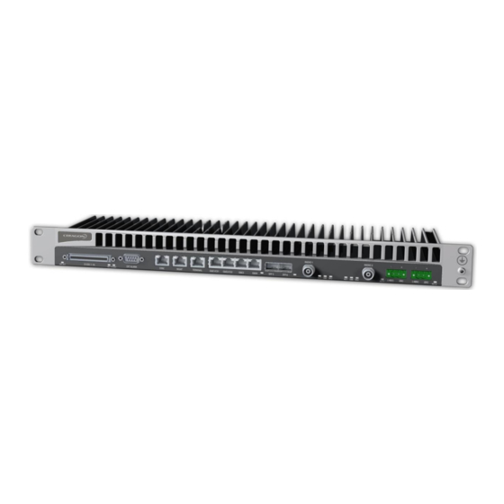
Ceragon FibeAir IP-20G Wireless Edge Node Manuals
Manuals and User Guides for Ceragon FibeAir IP-20G Wireless Edge Node. We have
4
Ceragon FibeAir IP-20G Wireless Edge Node manuals available for free PDF download: Technical Description, Installation Manual, User Manual
Ceragon FibeAir IP-20G Technical Description (266 pages)
Brand:
Ceragon
| Category:
Network Hardware
| Size: 6.72 MB
Table of Contents
Table of Contents
3
Synonyms and Acronyms
14
Introduction
17
Product Overview
18
IP-20G Radio Options
19
IP-20G Highlights
20
IP-20G Protection Options
20
IP-20 Platform Reference Topology
21
Reference Configurations
21
Fibeair IP-20 Platform Reference Topology
21
Reference Configuration - Dual Modem Activation
22
Dual Modem Activation
22
Reference Configuration - IDU Cascading with Dual Modems
23
IDU Cascading with Dual Modems
23
Reference Configuration - Chained Network
24
Chained Network
24
Reference Configuration - Ring with Spur
25
Ring with Spur
25
Reference Configuration - Aggregation/Pop Site
26
Aggregation/Pop Site
26
New Features in Version T7.9
27
IDU Hardware Description
29
Hardware Architecture
30
IP-20G Block Diagram
31
IP-20G Interfaces
32
IP-20G Front Panel and Interfaces
32
Front Panel Description
32
Electrical GE Interface Leds
33
Ethernet Traffic Interfaces
33
Optical GE Interface LED
34
2 X FE Splitter Cable Marketing Model
35
Management Interface Pin Connections
35
Ethernet Management Interfaces
35
Management FE Interface Leds
36
TDM Interface Leds
37
E1 Interface (Optional)
37
Radio Interfaces
38
Radio Interface Leds
39
Power Interface Leds
40
Power Interfaces
40
Sync Interface Leds
41
Synchronization Interface
41
Terminal Interface
42
Unit/Act LED
42
External Alarms
43
SM Card and Cover
44
Storage Memory Card
44
RFU Hardware Description and Branching Options
45
RFU Overview
46
RFU Selection Guide
47
Rfu-C
48
Main Features of RFU-C
48
1500Hp/Rfu-Hp
49
Main Features of 1500HP/RFU-HP
49
1500HP 2RX in 1+0 SD Configuration
51
1500HP 1RX in 1+0 SD Configuration
51
1500HP/RFU-HP Functional Block Diagram and Concept of Operation
51
1500HP/RFU-HP Comparison Table
53
1500HP/RFU-HP System Configurations
53
Split Mount Configuration and Branching Network
54
Space Diversity with if Combining
54
All-Indoor Vertical Branching
55
Ld OCB
56
OCB and DCB Block Diagram
57
OCB Component Summary
58
1500HP/RFU-HP Models and Part Numbers
59
OCB Part Numbers
59
RFU Models - 1RX Units
59
RFU Models - 2RX Units
59
OCB Part Numbers for All Indoor Compact
60
Activation Keys
61
Working with Activation Keys
62
Demo Mode
62
Activation Key-Enabled Features
62
Activation Key Types
62
Capacity Activation Key Levels
64
CET Node Activation Key Levels
65
Feature Description
66
Innovative Techniques to Boost Capacity and Reduce Latency
67
Capacity Summary
68
Header De-Duplication
69
Header De-Duplication Potential Throughput Savings Per Layer
70
Latency
72
Frame Cut-Through
73
Propagation Delay with and Without Frame Cut-Through
73
Frame Cut-Through Operation
74
Radio Features
75
Adaptive Coding Modulation (ACM)
76
ACM Working Points (Profiles)
76
Adaptive Coding and Modulation with 10 Working Points
77
Dual Polarization
79
Cross Polarization Interference Canceller (XPIC)
79
XPIC Implementation
80
XPIC - Impact of Misalignments and Channel Degradation
80
1+1 HSB Radio Protection
82
Path Loss on Secondary Path of 1+1 HSB Protection Link
83
Atpc
84
Multi-Carrier ABC Traffic Flow
85
Multi-Carrier ABC
85
Direct and Reflected Signals
87
BBS Space Diversity
87
1+1 BBS Space Diversity Configuration - Receiving Side
88
Radio Utilization Pms
89
Ethernet Features
90
Basic Ethernet Service Model
91
Ethernet Services Overview
91
Ethernet Virtual Connection (EVC)
92
Point to Point EVC
93
Multipoint to Multipoint EVC
93
Rooted Multipoint EVC
93
MEF Ethernet Services Definition Framework
95
MEF-Defined Ethernet Service Types
95
E-Line Service Type Using Point-To-Point EVC
96
EPL Application Example
97
EVPL Application Example
97
E-LAN Service Type Using Multipoint-To-Multipoint EVC
98
Adding a Site Using an E-Line Service
99
Adding a Site Using an E-LAN Service
99
MEF Ethernet Private LAN Example
100
MEF Ethernet Virtual Private LAN Example
101
E-Tree Service Type Using Rooted-Multipoint EVC
101
E-Tree Service Type Using Multiple Roots
102
MEF Ethernet Private Tree Example
102
Ethernet Virtual Private Tree Example
103
Mobile Backhaul Reference Model
104
Packet Service Core Building Blocks
104
IP-20G's Ethernet Capabilities
106
Supported Standards
107
Ethernet Service Model
108
IP-20G Services Model
108
IP-20G Services Core
109
Multipoint Service
110
IP-20G Services Flow
110
Point-To-Point Service
110
Ethernet Services Learning and Forwarding
113
Management Service
114
Management Service and Its Service Points
116
Saps and Snps
117
Pipe Service Points
118
SAP, SNP and Pipe Service Points in a Microwave Network
118
Service Point Types Per Service Type
119
Service Point Types that Can Co-Exist on the same Interface
120
Service Point Type-Attached Interface Type Combinations that Can Co-Exist on the same Interface
121
Service Path Relationship on Point-To-Point Service Path
122
Physical and Logical Interfaces
125
Ethernet Interfaces
125
Grouped Interfaces as a Single Logical Interface on Ingress Side
126
Grouped Interfaces as a Single Logical Interface on Egress Side
126
Relationship of Logical Interfaces to the Switching Fabric
130
Qos Block Diagram
134
Quality of Service (Qos)
134
Standard Qos and H-Qos Comparison
136
Hierarchical Classification
137
Classification Method Priorities
138
C-VLAN 802.1 up and CFI Default Mapping to Cos and Color
138
S-VLAN 802.1 up and DEI Default Mapping to Cos and Color
139
DSCP Default Mapping to Cos and Color
139
MPLS EXP Default Mapping to Cos and Color
140
Ingress Policing Model
142
IP-20G Queue Manager
145
Synchronized Packet Loss
146
Random Packet Loss with Increased Capacity Utilization Using WRED
147
WRED Profile Curve
148
Detailed H-Qos Diagram
151
Scheduling Mechanism for a Single Service Bundle
154
Qos Priority Profile Example
155
WFQ Profile Example
157
UP Marking Table (C-VLAN)
159
Ad up Marking Table (S-VLAN)
160
Summary and Comparison of Standard Qos and H-Qos
161
Global Switch Configuration
162
Automatic State Propagation
163
Network Resiliency
164
G.8032 Ring in Idle (Normal) State
165
G.8032 Ring in Protecting State
166
Load Balancing Example in G.8032 Ring
166
IP-20G End-To-End Service Management
170
6.3.10 Oam
170
SOAM Maintenance Entities (Example)
171
Ethernet Line Interface Loopback - Application Examples
172
Synchronization
173
Synchronization Overview
174
Precision Timing Protocol (PTP) Synchronization
175
Synchronous Ethernet (Synce)
176
IP-20G Synchronization Solution
176
Synchronization Input Options
177
Synchronization Output Options
177
Available Synchronization Interfaces
177
Configuring Native Sync Distribution
177
Synchronization Configuration
178
Native Sync Distribution Mode
179
Native Sync Distribution Mode Usage Example
180
Native Sync Distribution Mode - Tree Scenario
181
Native Sync Distribution Mode - Ring Scenario (Normal Operation)
181
Native Sync Distribution Mode - Ring Scenario (Link Failure)
182
Synce PRC Pipe Regenerator Mode
183
SSM Support and Loop Prevention
183
Hybrid Ethernet and TDM Services
185
Hybrid Ethernet and TDM Services Carried over Cascading Interfaces
185
TDM Services
185
Hybrid Ethernet and Native TDM Services
186
Native TDM Trails
186
1:1 TDM Path Protection - Ring Topology
187
1+1 TDM Path Protection - Dual Homing Topology
188
All-Packet Ethernet and TDM Pseudowire Services
190
TDM Pseudowire
190
Native TDM Trail Interoperability with Optical SDH Equipment
196
Native TDM Trail Interoperability with TDM Pseudowire-Over-Packet Aggregation
196
TDM Pseudowire Interoperability with Optical SDH Equipment
196
TDM Reference Solutions
196
TDM Pseudowire Interoperability with Third-Party Packet Aggregation Equipment
197
Fibeair IP-20G Management
198
Integrated IP-20G Management Tools
199
Management Overview
199
Automatic Network Topology Discovery with LLDP Protocol
200
Management Communication Channels and Protocols
201
Dedicated Management Ports
201
NMS Server Receiving Data Ports
202
Web Sending Data Ports
202
Web Receiving Data Ports
202
Additional Management Ports for IP-20G
202
Web-Based Element Management System (Web EMS)
203
Command Line Interface (CLI)
204
Configuration Management
204
Software Management
205
Backup Software Version
206
Ipv6 Support
207
In-Band Management
207
Local Management
207
Alarms
208
7.11.1 Configurable RSL Threshold Alarms and Traps
208
7.11.2 Alarms Editing
208
External Alarms
209
NTP Support
209
UTC Support
209
System Security Features
210
7.15.1 Ceragon's Layered Security Concept
210
Security Solution Architecture Concept
210
7.15.2 Defenses in Management Communication Channels
211
7.15.3 Defenses in User and System Authentication Procedures
212
7.15.4 Secure Communication Channels
214
7.15.5 Security Log
216
Standards and Certifications
218
Supported Ethernet Standards
219
Supported MEF Specifications
220
MEF Certifications
220
MEF Certifications for Ethernet Services
220
Supported TDM Pseudowire Encapsulations
221
Standards Compliance
221
Network Management, Diagnostics, Status, and Alarms
222
Specifications
223
General Radio Specifications
224
Radio Capacity Specifications
225
Radio Capacity Specifications (no XPIC)
225
Radio Capacity Specifications with XPIC
230
Transmit Power Specifications (Dbm)
233
Transmit Power with RFU-C (Dbm)
233
Transmit Power with 1500HP/RFU-HP (Dbm)
234
Receiver Threshold (RSL) Specifications (Dbm @ BER = 10-6)
235
RFU-C Receiver Threshold (RSL) (Dbm @ BER = 10-6)
235
Receiver Thresholds with RFU-HP
238
Receiver Thresholds with 1500HP
240
Frequency Bands
242
Frequency Bands - RFU-C and RFU-Ce
242
Frequency Bands - 1500HP and RFU-HP
253
Mediation Device Losses
254
RFU-C Mediation Device Losses
254
1500HP/RFU-HP Branching Network Losses
255
Ethernet Latency Specifications
257
Ethernet Specifications
260
Ethernet Interface Specifications
260
Carrier Ethernet Functionality
260
TDM Specifications
261
E1 Cross Connect
261
E1 Interface Specifications
261
Synchronization Specifications
261
Mechanical Specifications
262
IDU Mechanical Specifications
262
RFU-C Mechanical Specifications
262
1500HP/RFUHP Mechanical Specifications
262
Environmental Specifications
263
9.12.1 Environmental Specifications for IDU
263
9.12.2 Environmental Specifications for RFU
263
Supported Antenna Types
264
9.13.1 RFU-C Antenna Connection
264
9.13.2 1500HP/RFU-HP Antenna Connection
264
RFU-C - Waveguide Flanges
265
1500HP/RFU-HP - Waveguide Flanges
265
Waveguide Specifications
265
9.14.1 RFU-C Waveguide Specifications
265
9.14.2 1500HP/RFU-HP Waveguide Specifications
265
Power Input Specifications
266
Power Consumption Specifications
266
Advertisement
Ceragon FibeAir IP-20G Installation Manual (49 pages)
Brand:
Ceragon
| Category:
Network Hardware
| Size: 0.93 MB
Table of Contents
Installation Guide
1
Information to User
2
Table of Contents
3
About this Guide
10
Related Documents
10
Target Audience
10
What You Should Know
10
1 Fibeair IP-20G Hardware Overview
11
Figure 1: IP-20G Front Panel and Interfaces
11
Ethernet Traffic Interfaces
12
Ethernet Management Interfaces
13
Management Interface Cable Options
13
TDM Interfaces (E1/DS1 1X16) (Optional)
13
Figure 2: Management Interface Pin Connections
13
Table 1: 2 X FE Splitter Cable Marketing Model
13
Radio Interfaces
14
Power Interfaces
14
Synchronization Interface
14
Terminal Interface
14
External Alarms
15
Fibeair IP-20 Assured Platform
16
2 Preparing for Installation
17
Transportation/Storage
17
Inspection
17
Unpacking Equipment at the Site
18
3 Installing the IP-20G IDU
19
Kits Required to Perform the Installation
19
Tools
19
Figure 3: IDU (Full Configuration)
19
Installing the IP-20G IDU in the Rack (19")
20
Grounding the IP-20G
21
Replacing an IP-20G IDU or SM-Card
22
4 Connecting the Power Cable
24
Figure 4: Power Supply Grounding
24
Figure 5: Correct Wiring of Power Connector
25
Figure 6: Connecting the Power Cable
25
Power Supply Notes
26
5 Cabling Requirements for Unit Redundancy
27
Cabling for Ethernet Interfaces
27
Cabling for E1/DS1 Interfaces
27
Cabling for T3 Synchronization
27
Table 2: Y-Cable for Electrical Splitter Mode FE Traffic Interface Protection
27
Table 3: Y-Cable for E1/DS1 Protection
27
Inter-IDU Protection Connectivity and Management
28
Figure 7: IP-20G with Unit Redundancy - Protection and Management Connection
28
Table 4: Splitter Cable for Protection and Management
28
6 Performing Initial Configuration
29
Establishing a Connection
29
Connecting to the Unit with a Serial Connection
29
Figure 8: Terminal Interface
29
Connecting to the Unit with a LAN Connection
30
Figure 9: Management Interface
30
Logging on
31
Figure 10: Login Window
31
Changing Your Password
32
Figure 11: Change User Password Page
32
Configuration
33
Applying a Pre-Defined Configuration File
34
Figure 12: Quick Configuration - from File Page
34
Figure 13: Quick Configuration - from File Page - Configuration File Loaded
35
7 Specifications
36
Environmental Specifications for IDU
36
Environmental Specifications for RFU
36
Mechanical Specifications
37
Table 5: IDU Mechanical Specifications
37
Table 6: RFU-C Mechanical Specifications
37
Power Consumption Specifications
38
8 Acceptance & Commissioning Procedures
39
Site Acceptance Procedure
40
Site Acceptance Checklist Notes
44
Radio Link Commissioning Procedure
46
Scope
46
Commissioning Test
46
IP-20 Commissioning Log
47
Ceragon FibeAir IP-20G Installation Manual (36 pages)
Brand:
Ceragon
| Category:
Network Hardware
| Size: 2.39 MB
Table of Contents
Information to User
2
Table of Contents
3
About this Guide
8
Related Documents
8
Target Audience
8
What You Should Know
8
1 Fibeair IP-20G Hardware Overview
9
Ethernet Traffic Interfaces
10
Ethernet Traffic Interface Leds
10
Ethernet Traffic Interface Pin-Outs
11
Ethernet Management Interfaces
12
Management Interface Cable Options
12
Management Interface Leds
12
Management Interface Pin-Outs
13
TDM Interfaces (E1/DS1 1X16) (Optional)
13
E1/DS1 Interface Leds
13
E1/DS1 Interface Pin-Outs
14
Radio Interfaces
16
Radio Interface Leds
16
Power Interfaces
18
Power Interface Leds
18
Synchronization Interface
19
Synchronization Interface Leds
19
Synchronization Interface Pin-Outs
20
Terminal Interface
20
Terminal Interface Pin-Outs
20
External Alarms
21
External Alarm Pin-Outs
21
Unit/Act LED
22
2 Preparing for Installation
23
Transportation/Storage
23
Inspection
23
Unpacking Equipment at the Site
23
3 Installing the IP-20G IDU
25
Kits Required to Perform the Installation
25
Tools
25
Installing the IP-20G IDU in the Rack (19")
25
Grounding the IP-20G
26
Replacing an IP-20G IDU or SM-Card
27
4 Connecting the Power Cable
29
Power Supply Notes
31
5 Performing Initial Configuration
32
Establishing a Connection
32
Connecting to the Unit with a Serial Connection
32
Connecting to the Unit with a LAN Connection
33
Logging on
33
Configuration
34
6 Specifications
35
Environmental Specifications for IDU
35
Environmental Specifications for RFU
35
Mechanical Specifications
35
Power Consumption Specifications
36
Advertisement
Ceragon FibeAir IP-20G User Manual (20 pages)
Brand:
Ceragon
| Category:
Network Hardware
| Size: 0.85 MB
Table of Contents
Statement of Conditions
2
Information to User
2
Safety Precautions & Declared Material
16
General Equipment Precautions
16
Special Requirements for North America
17
Précautions Générales Relatives À L'équipement
19
Allgemeine Vorsichtsmaßnahmen für die Anlage
19
Advertisement
Related Products
Ceragon Fibe-Air IP-10G
Ceragon FibeAir IP-20 All-Outdoor Series
Ceragon FibeAir IP-20E
Ceragon FibeAir IP-20S
Ceragon FibeAir IP-20V-ESP-38IA
Ceragon FibeAir IP-20V Series
Ceragon FibeAir IP-20V-C-ESP-38IA
Ceragon Evolution IP-20LH
Ceragon FibeAir IP-20C
Ceragon FibeAir IP-20C-HP
Ceragon Categories
Network Hardware
Wireless Access Point
Transmitter
Switch
Wireless Router
More Ceragon Manuals
Login
Sign In
OR
Sign in with Facebook
Sign in with Google
Upload manual
Upload from disk
Upload from URL