Table of Contents
Advertisement
Quick Links
User Guide
Viega Non-Programmable
Heat/Cool Thermostat
Part Number 15116
This document is subject to updates.
For the most current Viega technical
literature please visit www.viega.us.
Viega products are designed to be
installed by licensed and trained
plumbing, mechanical, and electrical
professionals who are familiar with Viega
products and their installation.
Installation by non-professionals may
void Viega LLC's warranty.
CAUTION! Electrical Hazard
Failure to disconnect the power
before beginning to install this
product can cause electrical shock or
equipment damage.
MERCURY NOTICE
All of our products are mercury
free. However, if the product you
are replacing contains mercury, dispose of
it properly. Your local waste management
authority can give you instructions on
recycling and proper disposal.
UG-HC 566439 1219 Nonprogrammable Thermostat
Installation Tips
Applications Guide
The Programmable Heat/Cool Thermostat can
be use for the following applications:
■
Gas or Oil Heat
■
Electric Furnace
■
Heat Pump (No Aux. or Emergency Heat)
■
Heat Only Systems
■
Cool Only Systems
The following applications are not recommended:
■
Heat Pump (with Aux. or Emergency Heat)
■
Multi-stage Systems
Wall Locations
The thermostat should be installed approximately
4 to 5 feet above the floor. Select an area with
average temperature and good air circulation.
No
No
Do not install thermostat in locations:
■
Close to heating/cooling emitters
■
That are in direct sunlight
■
With an outside wall behind the thermostat
■
In areas that do not require conditioning
■
Where there are dead spots or drafts
(in corners or behind doors
■
Where there might be concealed chimneys or pipes
Pick an installation location that is
easy for the user to access. The
temperature of the location should be
representative of the building
No
Yes
1 of 12
Advertisement
Table of Contents

Related Manuals for Viega 15116


Summary of Contents for Viega 15116
-
Page 1: User Guide
Wall Locations This document is subject to updates. The thermostat should be installed approximately For the most current Viega technical 4 to 5 feet above the floor. Select an area with literature please visit www.viega.us. average temperature and good air circulation. -
Page 2: Mounting The Subbase
Viega Nonprogrammable Thermostat User Guide Mounting the Subbase Attaching the Thermostat to the Subbase Align the 4 tabs on the subbase with corresponding slots on the back of the thermostat, then push gently until the thermostat snaps in place. To insure a solid fit between the thermostat and the subbase: ■... -
Page 3: Battery Installation
Viega Nonprogrammable Thermostat User Guide Battery Installation Thermostat Settings Battery installation is recommended even if thermostat is hardwired (C terminal connected). When thermostat is hardwired and batteries are installed, the thermostat will activate a compressor delay of 5 minutes when the thermostat detects a power outage from the hardwired power supply. -
Page 4: Thermostat Wiring
Viega Nonprogrammable Thermostat User Guide Thermostat Wiring Wiring Tips ■ If you are replacing a thermostat, make note RH & RC terminals of the terminal connections on the thermostat that is being replaced. In some cases the For single transformer systems, leave the jumper wiring connections will not be color coded. - Page 5 Viega Nonprogrammable Thermostat User Guide Typical Industry Wiring Diagrams Power supply Use a small piece of wire (not supplied) to connect W and Y terminals Factory-installed jumper. Remove only when installing on 2-transformer systems Set fan operation setting to Electric...
- Page 6 Viega Nonprogrammable Thermostat User Guide Viega Wiring Diagrams Connecting Viega Thermostats and Zone Valves to the Viega Zone Control Thermostat 15116 Thermostat 15117 Thermostat 15118 Thermostat 18050 Zone Control (18060, 18062) with Optional Priority Viega Viega Viega Part Numbers: 15116, 15117, and 15118 Legend: Thermostat ■...
- Page 7 Viega Nonprogrammable Thermostat User Guide Viega Wiring Diagrams Connecting Viega Thermostats to the Viega Zone Control Thermostat 15116 Thermostat 15117 Thermostat 15118 Thermostat 18050 Zone Control (18060, 18062) with Optional Priority Viega Viega Powerhead (15061, 15070) Viega Viega 2 Wire, 24 V...
- Page 8 Viega Nonprogrammable Thermostat User Guide Connecting Viega Thermostats Connecting Viega Thermostats to 2-Wire Powerheads to 4-Wire Powerheads Thermostat -15118 Thermostat -15118 Viega Viega Viega Black Yellow White Yellow 120 V AC 120 V AC Power Supply Class II Power Supply...
-
Page 9: Thermostat Display
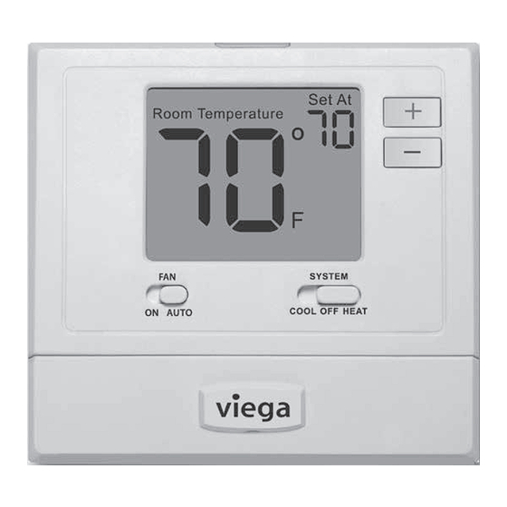
Viega Nonprogrammable Thermostat User Guide Thermostat Display LCD Display Glow in the dark light button ■ Push the glow in the dark button and screen will illuminate. Fan switch ■ Set to AUTO to run the fan anytime heating or cooling is running. -
Page 10: Programming The Thermostat
Viega Nonprogrammable Thermostat User Guide Programming the Thermostat Tech Settings To exit Tech settings, slide System Switch Select OFF with the System Switch. to different position or wait approximately 20 Hold down the + and - buttons together for 3 seconds. -
Page 11: Swing Settings
Viega Nonprogrammable Thermostat User Guide Swing Settings To exit Swing settings, slide System Switch Select COOL or HEAT with the System to different position or wait approximately 20 Switch. They are set separately. seconds. Hold down the + and - buttons together for 3 seconds. -
Page 12: Adjusting The Room Temperature
Viega Nonprogrammable Thermostat User Guide Adjusting the Room Temperature The current room temperature is displayed in large text in the center of the thermostat under the “room temperature” heading. The set point or desired room temperature is in the upper right corner of the display under “set at”.
Need help?
Do you have a question about the 15116 and is the answer not in the manual?
Questions and answers