Advertisement
Quick Links
LOVATO ELECTRIC S.P.A.
24020 GORLE (BERGAMO) ITALIA
VIA DON E. MAZZA, 12
TEL. 035 4282111
TELEFAX (Nazionale): 035 4282200
TELEFAX (International): +39 035 4282400
L
E
E-mail info@
ovato
lectric.com
L
E
Web
www.
ovato
lectric.com
I
RELÈ DIFFERENZIALI DI TERRA
GB EARTH LEAKAGE RELAYS
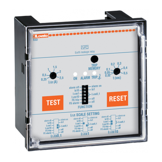
RELÈ DIFFERENZIALI DI TERRA R1D, R2D, R3D, R4D
2
6
8
1
2
4
3
5
1
Regolazione tempo ritardo di intervento (vedi anche punto 3b)
2
Regolazione corrente di guasto verso terra (vedi anche punto 3c)
3
Dip switch di programmazione:
3a) Versione R1D auto reset - man reset
auto reset = riarmo automatico
man reset = ripristino manuale tramite pulsante RESET
fronte. Per ripristinare a distanza è sufficiente togliere
l'alimentazione ausiliaria per circa 1 secondo.
Versioni R2D, R3D, R4D alarm off - alarm on
alarm off = preallarme intervento disattivato; al superamento del
valore di I∆n impostato si avrà lo scambio dei contatti di uscita e
l'accensione dei LED
ALARM e
alarm on = preallarme intervento attivato; al raggiungimento del
70% del valore di I∆n impostato, si avrà l'accensione del LED
ALARM e lo scambio dei contatti (terminali 4-5-6). Al
superamento del valore I∆n impostato si accenderà il LED
e scambieranno i contatti di TRIP (terminali 7-8-9)
3b) tx10 - tx1 selezione costante per la regolazione del tempo di
ritardo intervento.
Esempi: posizionando il dip switch su tx10 ed il potenziometro
su 0,3 avremo un ritardo di intervento al superamento della soglia
I∆n di 0,3x10 = 3 secondi; posizionando il dip switch su tx1 ed il
potenziometro
su 0,3 avremo un ritardo di intervento al
superamento della soglia I∆n di 0,3x1 = 0,3 secondi.
3c) I∆nx0,1 - I∆nx1 - I∆nx10 selezione costante per la
regolazione della corrente di guasto verso terra. Le costanti in
funzione della posizione dei 2 dip switch sono le seguenti:
- posizione dip switch I∆nx0,1 e I∆nx0,1 K = 0,1
- posizione dip switch I∆nx1
e I∆nx0,1 K = 1
- posizione dip switch I∆nx1
e I∆nx10 K = 10
Esempi: posizionando i dip switch su I∆nx0,1 e I∆nx0,1 ed il
potenziometro I∆n
su 1,5 avremo una soglia di intervento per
corrente di guasto verso terra I∆n di 1,5x0,1 = 0,15A;
posizionando i dip switch su I∆nx1 e I∆nx10 ed il potenziometro
I∆n
su 1,5 avremo una soglia di intervento per corrente di
guasto verso terra I∆n di 1,5x10 = 15A:
3d) Versioni R2D, R3D, R4D FS trip - off
FS trip = sicurezza positiva attivata su relè TRIP; in questa
condizione il relè di TRIP (terminali 7-8-9) è normalmente eccitato;
quindi nel caso di mancanza della tensione ausiliaria i contatti in
uscita si posizionano nella condizione di intervento (TRIP).
Off = sicurezza positiva disattivata. Relè TRIP normalmente
diseccitato.
3e) Versioni R2D, R3D, R4D FS alarm- off
FS alarm = sicurezza positiva attivata su relè ALARM; in questa
condizione il relè di preallarme ALARM (terminali 4-5-6) è
normalmente eccitato; quindi nel caso di mancanza della tensione
ausiliaria i contatti in uscita si posizionano nella condizione di
intervento (TRIP).
Off = sicurezza positiva disattivata. Relè ALARM normalmente
diseccitato.
4
Pulsante TEST. Provoca l'intervento del relè.
EARTH LEAKAGE RELAYS R1D, R2D, R3D, R4D
6
7
8
1
2
4
3
5
1
Tripping delay time adjustment (also see point 3b)
2
Fault current to earth adjustment (also see point 3c)
3
Dip switches setting:
3a) Version R1D auto reset - man reset
auto reset = automatic reset
sul
man reset = manual reset through the RESET
For remote resetting, simply shut off the auxiliary supply for
about 1 second.
Versions R2D, R3D, R4D alarm off - alarm on
alarm off = trip prealarm deactivated; upon exceeding the set I∆n
rate, output contact changeover takes place and LEDs
TRIP.
and
alarm on = trip prealarm activated; upon reaching 70% of the set
I∆n rate, LED
takes place (terminals 4-5-6). Upon exceeding the set I∆n rate
TRIP
LED
(terminals 7-8-9)
3b) tx10 - tx1 constant selection for tripping delay time
adjustment.
Examples: positioning the dip switch on tx10 and the
potentiometer
exceeding the I∆n threshold of 0.3x10 = 3 seconds; positioning
the dip switch on tx1 and the potentiometer
a tripping delay upon exceeding the I∆n threshold of 0.3x1 = 0.3
seconds.
3c) I∆nx0.1 - I∆nx1 - I∆nx10 constant selection for fault current
to earth adjustment. The constants in relation to the position of
the 2 dip switches are the following:
– dip switch position I∆nx0.1 and I∆nx0.1
– dip switch position I∆nx1
– dip switch position I∆nx1
Examples: positioning the dip switches on I∆nx0.1 and I∆nx0.1
and the potentiometer I∆n
tripping threshold I∆n of 1.5x0.1 = 0.15A; positioning the dip
switches on I∆nx1 and I∆nx10 and the potentiometer I∆n
1.5 we will have a fault current tripping threshold I∆n of 1.5x10 =
15A:
3d) Versions R2D, R3D, R4D FS trip - off
FS trip = positive safety activated on TRIP relay; in this condition
the TRIP relay (terminals 7-8-9) is normally energised; therefore
in the event of the lack of auxiliary voltage the output contacts
move to the tripping condition (TRIP).
Off = positive safety deactivated. TRIP relay normally de-
energised.
3e) Versions R2D, R3D, R4D FS alarm- off
FS alarm = positive safety activated on ALARM relay, in this
condition the prealarm relay ALARM (terminals 4-5-6) is
normally energised; therefore in the event of the lack of auxiliary
voltage the output contacts move to the trip condition (TRIP).
Off = positive safety deactivated. ALARM relay normally de-
energised.
4
TEST pushbutton. Causes tripping of the relay.
6
7
8
9
1
6
7
4
3
5
2
4
TRIP light up.
ALARM lights up and signal contact changeover
TRIP will light up and the TRIP contacts will change over
on 0.3 we will have a tripping delay upon
and I∆nx0.1
and I∆nx10
on 1.5 we will have a fault current
12
10
8
11
3
9
5
1
key on the front.
ALARM
on 0.3 we will have
K = 0.1
K = 1
K = 10
on
1
Advertisement

Related Manuals for LOVATO ELECTRIC R1D


Summary of Contents for LOVATO ELECTRIC R1D
- Page 1 RELÈ DIFFERENZIALI DI TERRA R1D, R2D, R3D, R4D EARTH LEAKAGE RELAYS R1D, R2D, R3D, R4D Regolazione tempo ritardo di intervento (vedi anche punto 3b) Tripping delay time adjustment (also see point 3b) Regolazione corrente di guasto verso terra (vedi anche punto 3c)
- Page 2 RESET pushbutton. To reset the relay after tripping. For remote ripristinare a distanza R1D è sufficiente togliere l’alimentazione reset of R1D, simply shut off the auxiliary supply for about 1 ausiliaria per circa 1 secondo. Per R2D, R3D, R4D collegare un second.
- Page 3 RESET key. To reset the relay after tripping. For remote reset of Pulsante RESET. Per il ripristino del relè dopo l’intervento. R1D, simply shut off the auxiliary supply for about Per ripristinare a distanza è sufficiente togliere l’alimentazione 1 second.
- Page 4 TRASFORMATORI DI CORRENTE TOROIDALI TOROIDAL CURRENT TRANSFORMERS I relè differenziali di terra R...D, RM e RM1 possono essere collegati The differential earth relays RD..., RM and RM1 can be connected to ai seguenti trasformatori di corrente toroidali: the following toroidal current transformers: 31 RT 35 Ø...
- Page 5 Terra / GRD Linea / Load Terra / GRD Linea / Load N L1L2 L3 N L1L2 L3 9 8 7 6 5 3 2 1 12 11 10 8 7 6 Trip Alarm/Trip Trip 5-6 - 24VAC/DC 1-2 - 24VAC/DC 5-7 - 48VAC/DC 1-3 - 48VAC/DC 5-6 - 110-125VAC/DC...
- Page 6 R1D - R2D - R3D RM1 - RM TIPO RC35 RC60 RC80 RC110 150 RT210 - RTA210 RT35 - RT60 - RT80 - RT110 - RX10 RTA110 TIPO RT35 — RT60 — RT80 — RT110 — RT210 RTA110 180 RTA210 310 RX10 —...