Diamond PIZZAFORM DP45-EK Instructions For Installation, Use And Maintenance Manual
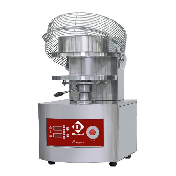
Hot pizza former
Hide thumbs
Also See for PIZZAFORM DP45-EK:
Table of Contents
Advertisement
Quick Links
Advertisement
Table of Contents

Related Manuals for Diamond PIZZAFORM DP45-EK


Summary of Contents for Diamond PIZZAFORM DP45-EK
- Page 1 07/2013 Mod: DP45-EK Production code: PZF/45DS...
- Page 2 PIZZAFORM HOT PIZZA FORMER INSTRUCTION FOR INSTALLATION, USE AND MAINTENANCE CUPPONE F.lli S.r.l.
- Page 3 June 2012 - Rev02...
-
Page 4: Table Of Contents
Index INSTALLATION DIAGRAM………….………………………………….…………………………………………. WIRING DIAGRAMS...…………………………………………………….……………………………………….. 1. Wiring diagram AC 3-N-400 50/60 Hz…..……………………………………………………………………. 2. Wiring diagram AC 3-230 50/60 Hz…...……………………………………………………………………… 3. Wiring diagram AC 230 50/60 Hz………..……………………………………………………………………. 4. Electrical data……...……………………..….………………………………………………………………….. III. GENERAL FEATURES…………………..………..…………………….……………………………………….. 1. Appliance description ………...……………………………………………………………………………….. 2. General recommendations…..…………………………….…………………………………………….……. 3. Environment protection…..………………………………………………….………………………………... IV. -
Page 5: Installation Diagram
INSTALLATION DIAGRAM Equipotential Cord socket MODEL EXTERNAL DIMENSIONS mm NET WEIGHT PZF/30DS PZF/35DS PZF/40DS PZF/45DS PZF/50DS... -
Page 6: Wiring Diagrams
WIRING DIAGRAMS Wiring diagram AC 3-N-400 50/60 Hz CTRL Control panel Lower heating element General contactor Upper heating element Closing contactor SQU1 Safety microswitch Opening contactor SQU2 Closing microswitch OFF button SQU3 Microinterruttore apertura Internal thermal cut-out SQU4 Opening microswitch... -
Page 7: Wiring Diagram Ac 3-230 50/60 Hz
Wiring diagram AC 3-230 50/60 Hz CTRL Control panel Lower heating element General contactor Upper heating element Closing contactor SQU1 Safety microswitch Opening contactor SQU2 Closing microswitch OFF button SQU3 Microinterruttore apertura Internal thermal cut-out SQU4 Opening microswitch... -
Page 8: Wiring Diagram Ac 230 50/60 Hz
Wiring diagram AC 230 50/60 Hz CTRL Control panel Lower heating element General contactor Upper heating element Closing contactor SQU1 Safety microswitch Opening contactor SQU2 Closing microswitch OFF button SQU3 Microinterruttore apertura Internal thermal cut-out SQU4 Opening microswitch... -
Page 9: Electrical Data
Electrical data MODEL VOLTAGE INPUT AMPERES CONNECTING CABLE AC 230 V 17.0 3x2.5 mm² AC 3 230 V 16.5 4x2.5 mm² PZF30DS AC 3 N 400 V 5x1 mm² AC 230 V 17.0 3x2.5 mm² AC 3 230 V 16.5 4x2.5 mm²... -
Page 10: Iii. General Features
III. GENERAL FEATURES Appliance description The present manual refers to different models of electronically controlled hot pizza forming from the PIZZAFORM series. The present manual was originally written in Italian. All other languages are translations. The main features of this machines series are as follows: •... -
Page 11: Instructions For Installation
IV. INSTRUCTION FOR INSTALLATION Legal and technical regulations and directives When installing this oven, you must comply with the following: • By-laws currently in effect. • Local building and fire-prevention regulations. • Regulations regarding electrical systems. • Accident-prevention regulations currently in effect. Positioning Unload the machine using suitable mechanical hoisting equipment. -
Page 12: Instructions For Use
INSTRUCTION FOR USE Control panel description The control panel, placed on the appliance’s front side, is made up as follows: 1. Display : shows the upper plate real temperature and the set one, plus plates contact time. 2. Led display 1 indicates switching on of the upper plate resistance. -
Page 13: Switching On, Setting Parameters, Switching Off
Switching on, setting parameters, switching off Reset the machine by turning the STOP button (12) clockwise. Switch on the machine by pressing the ON/OFF button (11). After a few seconds, display (1) will show the upper plate temperature and display (3) the lower plate temperature. -
Page 14: Warnings
Warnings If the guard is lifted when the lower plate is rising, the movement is stopped and reversed immediately. If the lower platen is unable to complete the flattening action due to unleavened dough or foreign matter between the plates, immediately raise the guard so that the movement is reversed. Key counting function With the card in the OFF position and the machine on, i.e. -
Page 15: Vi. Maintenance
VI. MAINTENANCE Cleaning Disconnect from the electricity supply and wait for the plates to cool down before carrying out any clean- ing or maintenance. ATTENTION: do not use jets of water, either direct or under pressure, for cleaning the appliance! Clean the exterior with a dry cloth, avoiding the use of solvents or products containing abrasive sub- stances or chlorates. -
Page 16: Errors Table
Tabella errori ERROR DESCRIPTION ERR (display 1) Ascent or descent time of the upper motor at default time. (display2) In this mode resistances power and plates handling are no longer on. To reset the functions switch off and on the machine. (display 1) Upper plate thermocouple faulty or not connected. -
Page 17: Spare Parts List
Spare parts list For spare part identification please refer to the attached enclosure. CODE DESCRIPTION 91310385 Red mushroom-head button 91310411 Contact NC 91611510 Front control panel 91310260 Control panel 91310171 Mechanical lock 91310136 Contactor (*) 91310230 Single-phase terminal block 91310231 Three-phase terminal block 91310231 Three-phase terminal block... -
Page 18: Exploded View
Exploded view... - Page 19 INSTALLED BY: DATE OF INSTALLATION: APPLIANCE CONTROLLED BY: DATE OF CONTROL:...
- Page 20 NOTES...
Need help?
Do you have a question about the PIZZAFORM DP45-EK and is the answer not in the manual?
Questions and answers