Table of Contents
Advertisement
Available languages
Available languages
Quick Links
INSTRUCTIONS
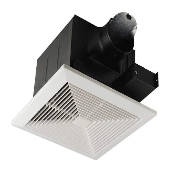
BATHROOM FAN
90 CFM: BV-BF-01
110 CFM: BV-BF-02
READ AND SAVE THESE INSTRUCTIONS
Please read these instructions carefully before installing, operating or servicing the fan.
Failure to comply with the instructions contained herein could result in personal injury
or property damage. We recommend that you keep this guide for future reference.
Table of contents
General information and parts .................................................................. 2
Description, sizes and wiring diagram ................................................... 3
Specications and dimensions
General safety information and warnings ............................................. 5
Installation I (joist mounting) ....................................................................... 6
Installation II (in existing ceiling) ................................................................ 7
Maintenance and limited warranty .......................................................... 8
................................................................. 4
1
Advertisement
Table of Contents

Related Manuals for BV BV-BF-01


Summary of Contents for BV BV-BF-01
- Page 1 INSTRUCTIONS BATHROOM FAN 90 CFM: BV-BF-01 110 CFM: BV-BF-02 READ AND SAVE THESE INSTRUCTIONS Please read these instructions carefully before installing, operating or servicing the fan. Failure to comply with the instructions contained herein could result in personal injury or property damage. We recommend that you keep this guide for future reference.
-
Page 2: General Information
General information You have to read the entire instruction guide prior to installing this fan. Parts supplied APPEARANCE PART NAME QUANTITY Grille Long wood screws Short screws Suspension brackets I Suspension brackets II... -
Page 3: Wiring Diagram
Description This product is designed with a built-in thermal cut-off for safety and long life of the motor. Sizes ” (31 cm) 9 ” (23 cm) 9 ” (23 cm) ” (32.07 cm) ” (32.07 cm) Wiring diagram 120 V AC 60 Hz Automatic terminal switch Black wire to switch... -
Page 4: Specifications
Specifications DUCT NOISE POWER SPEED AIR DELIVER AT WEIGHT DIRECTION DIAMETER (SONE) (RPM) 0.1” WG (CFM) 90 CFM 4” 24 W 1000 90 CFM 9.2 lb (10.16 cm) (4.18 kg) 110 CFM 4” 30 W 1160 110 CFM 9.2 lb (10.16 cm) (4.18 kg) Dimensions... - Page 5 9. Do not install in a cooking area. 10. Use this unit in the manner intended by the manufacturer. If you have any questions, please contact your BV store. 11. Installation work must be carried out by a qualified person, in accordance to all local and safety codes, including the rules for fire-rated constructions.
- Page 6 Installation I (joist mounting) 1. For ideal ventilation use, hold the body of the fan with the exhaust side facing the desired duct direction. 5. If the brackets are too short to reach the joist, use the extensions provided (Fig. E). Fig.
- Page 7 7. Electrical installation: Wires from the power supply to the unit should not be smaller than size 14 AWG. The ground wire must be connected to the green wire in junction box, the neutral wire to the white wire and the hot wire to the black wire. Installation II (in existing ceiling) 1.
- Page 8 Vacuum Limited warranty This is a quality product. It was made and selected with care and BV offers a limited one-year warranty against any manufacturing defects as long as it is used according to its intended use. BV will exchange any product that would show any such manufacturing...
-
Page 9: Table Of Contents
INSTRUCTIONS Ventilateur de salle de bains 90 PCM:BV-BF-01 110 PCM:BV-BF-02 VEUIL L E Z L I RE ET CONSERVER CES INSTRUCTIONS Veuillez lire attentivement les instructions avant d’installer ce ventilateur, de le faire fonctionner ou de l’entretenir. En ne vous conformant pas à... -
Page 10: Information Générale Et Pièces Fournies
Information générale Vous devez lire tout le guide avant d’installer ce ventilateur. Pièces fournies APPEARANCE PART NAME QUANTITY Grille Longues vis Courtes vis Supports I Supports II... -
Page 11: Description Et Dimensions Et Schéma De Câblage
Description Ce ventilateur a été concu est muni d’un coupe-circuit thermique pour assurer la sécurité et prolonger la vie du moteur. Formats ” (31 cm) 9 ” (23 cm) 9 ” (23 cm) ” (32.07 cm) ” (32.07 cm) Schéma de câblage 120 V Ca 60 Hz Borne du commutateur automatique Fil noir... -
Page 12: Caractéristiques Et Dimensions
Caractéristiques Consommation Vitesse Diamètre Niveau sonore Débit d’air à 0,25 cm Poids Sortie d’air énergétique (tours/minute) (0,1 po) GC (pi /min) (sone) du conduit 90 PCM 4” 24 W 1000 90 PCM 9.2 lb (10.16 cm) (4.18 kg) 110 PCM 4”... -
Page 13: Consignes De Sécurité Et Mises En Garde
10. N’utilisez cet appareil que de la façon prévue par le fabricant. Si vous avez des questions, veuillez communiquer avec BV votre détaillant. 11. Les travaux d’installation doivent être effectués par une personne qualifée, conformément aux codes locaux de sécurité, y compris les règlements relatifs aux installations pare-feu. -
Page 14: Installation I (Sur Solive)
Installation I (sur solive) Idéalement, tenez le boîtier du ventilateur en dirigeant le tuyau de sortie d’air dans la direction où il sera installé (ill. A). Si les supports sont trop courts pour atteindre la solive, utilisez les rallonges fournies (ill. E). Illustration A Illustration E Montez le corps du ventilateur entre les... -
Page 15: Installation Ii (Construction Existante)
7. Installation électrique Les fls électriques de la boîte électrique vers l’appareil ne devraient pas être de calibre inférieur à 14 AWG (calibrage américain normalisé des fls). Le fl de mise à la terre doit être branché au fl vert de la boîte de jonction, le fl de neutre au fl blanc et le fl du courant au fl noir. -
Page 16: Entretien Et Garantie Limitée
Garantie limitée C' e st un produit de qualité. Il a été fabriqué et sélectionné avec soin et BV offre une garantie limitée d' u n an contre tout vice de fabrication, à condition qu' i l soit utilisé conformément à l' u sage auquel il est destiné.
Need help?
Do you have a question about the BV-BF-01 and is the answer not in the manual?
Questions and answers