Table of Contents
Advertisement
This document explains how to install CX4 series hardware in cabinets
that conform to the National Electrical Manufacturer's Association
(NEMA) standards for 19-inch cabinets (in which the left and right
mounting channels are 19 inches apart). It covers mounting hardware
for 1U, 2U, 3U and 4U components, and filler panels that cover empty
cabinet spaces. In most cases, the illustrations and examples refer to
®
EMC
standard cabinets, which are 40U tall.
Topics are:
Device placement requirements ......................................................... 2
Power requirements ............................................................................. 4
Device height requirements ................................................................ 4
Installing a 1U SPS tray and SPS units in a cabinet......................... 6
Installing a 3U disk enclosure (DAE) in a cabinet ......................... 50
Installing front filler panels............................................................... 57
Note: Since EMC uses easily adjustable universal rails to mount these items in a
NEMA-standard cabinet, the instructions in this guide apply to non-EMC
cabinets as well.
Instructions for adding switches to an EMC storage system are included in the
device-specific documentation that accompanies the switch.
Rails and Enclosures
(CX4 Series Storage Systems)
Field Installation Guide
EMC
P/N 300-007-436
REV A02
August 13, 2008
1
Advertisement
Table of Contents

Related Manuals for EMC CX4 Series


Summary of Contents for EMC CX4 Series
-
Page 1: Table Of Contents
Installing a 3U disk enclosure (DAE) in a cabinet ......50 Installing front filler panels............... 57 Note: Since EMC uses easily adjustable universal rails to mount these items in a NEMA-standard cabinet, the instructions in this guide apply to non-EMC cabinets as well. -
Page 2: Device Placement Requirements
Before attaching the mounting rails or trays in any cabinet, you must decide where to put them. Where you install the devices depends on the kinds of devices you will install and the height of each device. EMC Rails and Enclosures (CX4 Series Storage Systems) Field Installation Guide... - Page 3 Review your plan to make sure all devices will fit in the cabinet, and review any requirements for filler panels. It is also important to verify cabling lengths before installing any enclosure. EMC Rails and Enclosures (CX4 Series Storage Systems) Field Installation Guide...
-
Page 4: Power Requirements
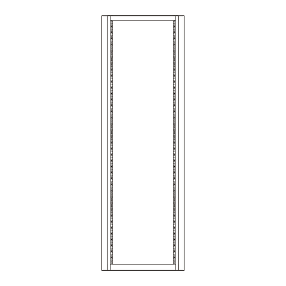
The holes are predrilled at distances of 1/2 inch, 5/8 inch, 5/8 inch (totaling one U), then 1/2 inch, 5/8 inch, 5/8 inch (another U), and so on. On EMC 40U and 40U-C cabinets, the 1U increments are marked by a horizontal line or small hole in the channel. - Page 5 3U, 5-1/4 in, 133 mm EMC DAE 4U, 7 in, 178 mm CX4-960 SPE 1U (1.75-in.) Increment EMC2205 U increments in a 40U cabinet front channel Figure 2 EMC Rails and Enclosures (CX4 Series Storage Systems) Field Installation Guide...
-
Page 6: Installing A 1U Sps Tray And Sps Units In A Cabinet
M4 x 8-mm panhead screw, lock washer, For back of tray and flat washer assemblies M4 x 10-mm flathead screws For front of tray and fastener bracket 2 latch brackets Secure 1U bezel EMC Rails and Enclosures (CX4 Series Storage Systems) Field Installation Guide... - Page 7 Figure 3 shows how to remove a common filler panel and latch bracket. CL4064 Removing a filler panel and latch bracket Figure 3 EMC Rails and Enclosures (CX4 Series Storage Systems) Field Installation Guide...
- Page 8 Figure Note: Leave the screws slightly loose to allow for adjustment after you install the tray. Do not insert a screw in the middle hole yet. EMC Rails and Enclosures (CX4 Series Storage Systems) Field Installation Guide...
- Page 9 Position the tray as shown in Figure 2. Slide the tray onto the mounting rails in the cabinet, until the flanges of the tray are flush with the cabinet channels. See Figure EMC Rails and Enclosures (CX4 Series Storage Systems) Field Installation Guide...
- Page 10 Figure If you are installing only a single SPS, insert it in the left side (facing the front of the cabinet) of the mounting tray. EMC Rails and Enclosures (CX4 Series Storage Systems) Field Installation Guide...
- Page 11 M4 x 10-mm flathead securing screws as shown in Figure 4. Insert and tighten the eight M4 x 8-mm panhead securing screws that secure the SPS units to the back of the tray, as shown in Figure EMC Rails and Enclosures (CX4 Series Storage Systems) Field Installation Guide...
- Page 12 SPS you just installed, refer to “Installing a 4U storage processor enclosure (SPE) in a cabinet” on page Next, cable the enclosures and SPS units as described in the appropriate setup guide. EMC Rails and Enclosures (CX4 Series Storage Systems) Field Installation Guide...
-
Page 13: Installing A 2U Storage Processor Enclosure (Spe) In A Cabinet
NEMA channels in a standard 19" cabinet EMC3248 Phillips M5 12.7 mm screws Attach the rail mounting hardware 2U bezel (front rack panel) EMI shielding CLARiiON CX4-240 CL4039 EMC Rails and Enclosures (CX4 Series Storage Systems) Field Installation Guide... - Page 14 NEMA-standard U measurement. The holes are predrilled at distances of 1/2 inch, 5/8 inch, 5/8 inch (totaling one U), then 1/2 inch, 5/8 inch, 5/8 inch (another U), and so on. On EMC 40U and 40U-C cabinets, horizontal lines or small holes in the channel mark the 1U increments.
- Page 15 7. From the rear of the cabinet, use two of the provided screws to secure each rail to the rear channel. Tighten the screws. EMC Rails and Enclosures (CX4 Series Storage Systems) Field Installation Guide...
- Page 16 Installing a 2U storage processor enclosure (SPE) in a cabinet Rear Front CL4110 Figure 11 Installing the adjustable mounting rails EMC Rails and Enclosures (CX4 Series Storage Systems) Field Installation Guide...
- Page 17 Para evitar daños personales o en el equipo, el compartimento no debe levantarse ni instalarse en el bastidor sin la ayuda de un elevador mecánico o de otra persona. EMC Rails and Enclosures (CX4 Series Storage Systems) Field Installation Guide...
- Page 18 2. Once the enclosure is completely seated into the rear tabs, tighten the two screws (one on each rail) that secure the rails to the front channels. EMC Rails and Enclosures (CX4 Series Storage Systems) Field Installation Guide...
- Page 19 For example, to add a disk array enclosure above the SPE you just installed, refer to “Installing a 3U disk enclosure (DAE) in a cabinet” on page EMC Rails and Enclosures (CX4 Series Storage Systems) Field Installation Guide...
-
Page 20: Installing A 2U Sps Tray (100-561-369) And Sps Units In A Cabinet
M5 x 10-mm panhead screw, lock washer, 10 for front of tray fastener and and flat washer assemblies latch brackets Left and right latch brackets Secure 2U bezel in 40U cabinets EMC3472 EMC Rails and Enclosures (CX4 Series Storage Systems) Field Installation Guide... - Page 21 Left Channel EMC2938a Removing a filler panel Figure 14 Adjusting the rails to your cabinet 1. Measure the distance between the inside edges of your front and back NEMA channels. EMC Rails and Enclosures (CX4 Series Storage Systems) Field Installation Guide...
- Page 22 2. From the front of the cabinet, insert the alignment pins on one mounting rail assembly into the appropriate holes of the selected 2U space on a rear channel. Figure 16 shows the correct channel holes for the alignment pins. EMC Rails and Enclosures (CX4 Series Storage Systems) Field Installation Guide...
- Page 23 Figure SPS adjustable rail Right rear Right front Screw (1) Screw (2) Mounting rail Alignment pin (2) Mounting rail EMC3461 Installing the 2U SPS adjustable rails Figure 17 EMC Rails and Enclosures (CX4 Series Storage Systems) Field Installation Guide...
- Page 24 Figure 18 3. Install the four M5 x 16mm securing screws (two on each side) that hold the 2U SPS tray to the front channels, as shown in Figure EMC Rails and Enclosures (CX4 Series Storage Systems) Field Installation Guide...
- Page 25 2U SPS tray to the mounting rails, as shown in Figure You have installed an SPS tray. Continue to the next section to install the SPS units. EMC Rails and Enclosures (CX4 Series Storage Systems) Field Installation Guide...
- Page 26 1. Remove the SPS units from their packaging. Working from the front of the cabinet, and with help from another person or mechanical lift, slide the SPS units onto the tray as shown in Figure EMC Rails and Enclosures (CX4 Series Storage Systems) Field Installation Guide...
- Page 27 M4 x 10-mm panhead securing screws as shown in Figure Rear Screw (8) to SPSs Front fastening bracket EMC3469 Installing the 2U SPS front fastening bracket Figure 21 EMC Rails and Enclosures (CX4 Series Storage Systems) Field Installation Guide...
- Page 28 2. Press the bezel onto the latch brackets until it snaps into place. CL4219 installing the latch bracket and bezel Figure 23 You have installed an SPS tray and SPS units in the cabinet. EMC Rails and Enclosures (CX4 Series Storage Systems) Field Installation Guide...
- Page 29 SPS you just installed, refer to “Installing a 4U storage processor enclosure (SPE) in a cabinet” on page Next, cable the enclosures and SPS units as described in the appropriate setup guide. EMC Rails and Enclosures (CX4 Series Storage Systems) Field Installation Guide...
-
Page 30: Installing A 2U Sps Tray (106-561-015) And Sps Units In A Cabinet
Supports two SPS units CL4097 Front fastener bracket Secure SPS units to tray CL4083 M5 x 10-mm panhead screw, lock washer, Secure tray to rails, and flat washer assemblies EMC Rails and Enclosures (CX4 Series Storage Systems) Field Installation Guide... - Page 31 Remove any filler panel, then use a flat-blade screwdriver or similar tool to pry off the latch brackets. Figure 24 shows how to remove a common filler panel and latch bracket. EMC Rails and Enclosures (CX4 Series Storage Systems) Field Installation Guide...
- Page 32 2. From the front of the cabinet, insert the alignment pins on one mounting rail assembly into the appropriate holes of the selected 2U space on a rear channel. Figure 25 shows the correct channel holes for the alignment pins. EMC Rails and Enclosures (CX4 Series Storage Systems) Field Installation Guide...
- Page 33 Figure SPS adjustable rail Right rear Right front Screw (2) Alignment Mounting rail pin (2) Mounting rail CL4104 Installing the 2U SPS adjustable rails Figure 26 EMC Rails and Enclosures (CX4 Series Storage Systems) Field Installation Guide...
- Page 34 Figure 27 3. Install the four M5 x 16mm securing screws (two on each side) that hold the 2U SPS tray to the front channels, as shown in Figure EMC Rails and Enclosures (CX4 Series Storage Systems) Field Installation Guide...
- Page 35 2U SPS tray to the mounting rails, as shown in Figure You have installed an SPS tray. Continue to the next section to install the SPS units. EMC Rails and Enclosures (CX4 Series Storage Systems) Field Installation Guide...
- Page 36 1. Remove the SPS units from their packaging. Working from the front of the cabinet, and with help from another person or mechanical lift, slide the SPS units onto the tray as shown in Figure EMC Rails and Enclosures (CX4 Series Storage Systems) Field Installation Guide...
- Page 37 Figure 29 2. Attach the front fastening bracket, and tighten the captive thumbscrews as shown in Figure Rear Front CL4085 Figure 30 Installing the 2U SPS front fastening bracket EMC Rails and Enclosures (CX4 Series Storage Systems) Field Installation Guide...
- Page 38 2. Press the bezel onto the latch brackets until it snaps into place. CL4103 Installing the latch brackets and bezel Figure 32 You have installed an SPS tray and SPS units in the cabinet. EMC Rails and Enclosures (CX4 Series Storage Systems) Field Installation Guide...
- Page 39 SPS you just installed, refer to “Installing a 4U storage processor enclosure (SPE) in a cabinet” on page Next, cable the enclosures and SPS units as described in the appropriate setup guide. EMC Rails and Enclosures (CX4 Series Storage Systems) Field Installation Guide...
-
Page 40: Installing A 4U Storage Processor Enclosure (Spe) In A Cabinet
2 adjustable rails (20.5-34 inches) Attach front to back on either side between NEMA channels in a standard 19" cabinet CL4062 Phillips M5 12.7 mm screws Attach the rail mounting hardware EMC Rails and Enclosures (CX4 Series Storage Systems) Field Installation Guide... - Page 41 Remove any filler panel, then use a flat-blade screwdriver or similar tool to pry off the latch brackets. Figure 33 shows how to remove a common filler panel and latch bracket. EMC Rails and Enclosures (CX4 Series Storage Systems) Field Installation Guide...
- Page 42 NEMA-standard U measurement. The holes are predrilled at distances of 1/2 inch, 5/8 inch, 5/8 inch (totaling one U), then 1/2 inch, 5/8 inch, 5/8 inch (another U), and so on. On EMC 40U and 40U-C cabinets, horizontal lines or small holes in the channel mark the 1U increments.
- Page 43 5. Repeat steps 2 through 4 on the left side, with the left rail. 6. From the rear of the cabinet, use two of the provided panhead screws to secure each rail to the rear channel. Tighten the screws. EMC Rails and Enclosures (CX4 Series Storage Systems) Field Installation Guide...
- Page 44 Alignment pins Adjustable rail Right rear Right front Screw (2) Screw (2) Alignment pin (2) Mounting rail Mounting rail CL4071 Installing adjustable mounting rails for a 4U enclosure Figure 35 EMC Rails and Enclosures (CX4 Series Storage Systems) Field Installation Guide...
- Page 45 Follow these steps to install the enclosure on the rails in the cabinet: 1. With help from another person, lift the enclosure and, from the front of the cabinet, slide the enclosure onto the rails as shown in Figure EMC Rails and Enclosures (CX4 Series Storage Systems) Field Installation Guide...
- Page 46 Extend the power supply handle to install three (3) 8x32 flathead screws to each side of the SPE. These screws secure the SPE to the adjustable rails. Refer to Figure Repeat for the other side. EMC Rails and Enclosures (CX4 Series Storage Systems) Field Installation Guide...
- Page 47 4. Tighten the four screws (two on each rail) that secure the rails to the front channels. 5. Assemble the latch brackets. See Figure CL4070 Assembling the latch brackets Figure 38 EMC Rails and Enclosures (CX4 Series Storage Systems) Field Installation Guide...
- Page 48 7. Press the front bezel onto the latch brackets at the front of the cabinet until it snaps into place, then lock the bezel with the key. Figure CL4074 Attaching the 4U front bezel Figure 40 EMC Rails and Enclosures (CX4 Series Storage Systems) Field Installation Guide...
- Page 49 SPE you just installed, refer to “Installing a 3U disk enclosure (DAE) in a cabinet” on page Next, cable the enclosures and SPS units as described in the appropriate setup guide. EMC Rails and Enclosures (CX4 Series Storage Systems) Field Installation Guide...
-
Page 50: Installing A 3U Disk Enclosure (Dae) In A Cabinet
Attach front to back on either side between NEMA channels in a standard 19" cabinet EMC3248 12 Phillips M5 12.7 mm screws Attach the rail mounting hardware 3U bezel (front rack panel) EMI shielding CL4141 EMC Rails and Enclosures (CX4 Series Storage Systems) Field Installation Guide... - Page 51 NEMA-standard U measurement. The holes are predrilled at distances of 1/2 inch, 5/8 inch, 5/8 inch (totaling one U), then 1/2 inch, 5/8 inch, 5/8 inch (another U), and so on. On EMC 40U and 40U-C cabinets, horizontal lines or small holes in the channel mark the 1U increments.
- Page 52 Rear Channels Alignment pins EMC2892a Adjustable rail Right rear Right front Screw (2) Screw (2) Alignment pin (2) Mounting rail Mounting rail EMC3452 Installing the adjustable mounting rails Figure 42 EMC Rails and Enclosures (CX4 Series Storage Systems) Field Installation Guide...
- Page 53 CAUTION Without proper equipment and procedures, you risk damaging disk drives any time you remove, store, or install them. Do not remove disks prior to installing the chassis. EMC Rails and Enclosures (CX4 Series Storage Systems) Field Installation Guide...
- Page 54 Note: If the chassis does not slide all the way into the cabinet, you may need to further loosen the screws that hold the rear of the rails in place, then adjust the rails to allow the tabs to fit into the notches. EMC Rails and Enclosures (CX4 Series Storage Systems) Field Installation Guide...
- Page 55 If you are installing the enclosure in a NEBS-compliant environment, secure the unit to the front channels with the four shape thread rolling screws supplied with your installation hardware in part number 100-560-644. EMC Rails and Enclosures (CX4 Series Storage Systems) Field Installation Guide...
- Page 56 6. If you are installing another device in the cabinet, continue with the appropriate instructions. Next, cable the enclosure and any SPS units as described in the appropriate hardware reference manual. EMC Rails and Enclosures (CX4 Series Storage Systems) Field Installation Guide...
-
Page 57: Installing Front Filler Panels
See Figure 47 for the location of the 2U latch bracket on the channels. Latch Bracket Here EMC2895 Location of the 1U and 2U latch bracket Figure 47 EMC Rails and Enclosures (CX4 Series Storage Systems) Field Installation Guide... - Page 58 6. Push the latch bracket onto the front channel until it locks into place. Notches Right Bracket in Place 3 Holes Channel EMC2890 Installing the 1U or 2U latch bracket on the right channel Figure 49 EMC Rails and Enclosures (CX4 Series Storage Systems) Field Installation Guide...
- Page 59 3. Push the latch bracket onto the front channel until it locks into place. Notch Left Bracket in Place Channel 2 Holes EMC2894 Installing the 3U latch bracket on the left channel Figure 51 EMC Rails and Enclosures (CX4 Series Storage Systems) Field Installation Guide...
- Page 60 You will install all of the filler panels on the latch brackets in the same way. 1. Align the vertical slots on the back of the filler panel with the latch bracket. EMC Rails and Enclosures (CX4 Series Storage Systems) Field Installation Guide...
- Page 61 Figure 53 3. To remove the filler panel, press the two buttons (usually on the corners) on the front of the filler panel, and pull the panel toward you. EMC Rails and Enclosures (CX4 Series Storage Systems) Field Installation Guide...
- Page 62 Installing front filler panels Copyright © 2008 EMC Corporation. All rights reserved. EMC believes the information in this publication is accurate as of its publication date. The information is subject to change without notice. THE INFORMATION IN THIS PUBLICATION IS PROVIDED “AS IS.” EMC CORPORATION MAKES NO...
Need help?
Do you have a question about the CX4 Series and is the answer not in the manual?
Questions and answers