
Related Manuals for Pentair AQUATIC ECO-SYSTEMS SAFEGUARD UV SYSTEMS Series


Summary of Contents for Pentair AQUATIC ECO-SYSTEMS SAFEGUARD UV SYSTEMS Series
- Page 1 AQUATIC ECO-SYSTEMS ® SAFEGUARD UV SYSTEMS ™ PLC PANEL INSTALLATION AND USER’S GUIDE IMPORTANT SAFETY INSTRUCTIONS READ AND FOLLOW ALL INSTRUCTIONS SAVE THESE INSTRUCTIONS...
-
Page 2: Table Of Contents
CUSTOMER SERVICE / TECHNICAL SUPPORT If you have questions about ordering Pentair Aquatic Eco-Systems replacement parts and products, please use the ® following contact information: Customer Service Web site 8 AM to 7 PM — Eastern and Pacific Times Visit www.pentairaes.com... -
Page 3: Section 1: Introduction
UV system will be required to perform his/her own verifications and safety measures. Pentair Aquatic Eco-Systems, Inc. accepts no responsibility for any problems arising from incorrect installation, lack of routine maintenance as specified in this manual or modifications of the UV system. -
Page 4: Section 2: Health And Safety Precautions
To avoid possible electric shock special care should be taken since water is employed in the use of the UV System. For each of the following situations, do not attempt repairs yourself. Call Pentair Aquatic Eco-Systems, Inc customer service department at 877-347-4788. -
Page 5: Hazardous Situations And Appropriate Actions
IMPORTANT: Each UV system is designed for a specific water-pressure. DO NOT use the UV system for any application other than its intended use. The use of attachments not recommended or sold by Pentair Aquatic Eco-Systems may cause unsafe conditions and possibly void any warranty. -
Page 6: Section 3: System Overview
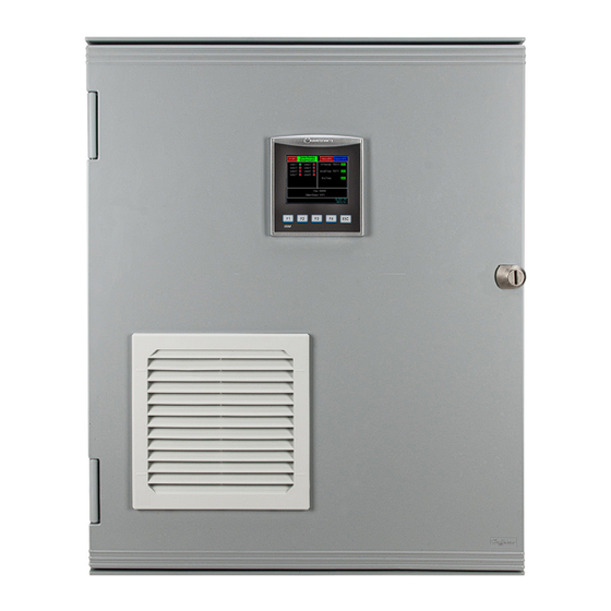
SECTION THREE SYSTEM OVERVIEW System Features • UL 508A listed Power Supply Enclosure. • NEMA Type-12 High-Impact, Thermopolymer Enclosure with professionally assembled electrical hardware and instrumentation. • Basic PLC or Advanced PLC Power Supply Enclosure. Power Enclosure The Remote Power Enclosure houses all components used for operation, monitoring and control of the entire SafeGUARD UV Systems™... -
Page 7: Section 4: Power Supply Installation
SECTION FOUR POWER SUPPLY INSTALLATION Power Supply Installation Purpose Power Supply Enclosure is part of the complete SafeGUARD UV Systems™ Series. Frequency Required with new construction, retro-fit or replacement of outdated equipment. Parts and Required Equipment • Set of Slot and Phillips Head Screwdrivers •... -
Page 8: Terminals
Terminals located bottom of the panel are referenced from left to right. Main Power Power Connection (120 VAC) • Locate Terminals 01 (Black), 02 (White), and 03 (Green). • Connect Line to terminal 01 (Black). • Connect Neutral to terminal 02 (White). •... - Page 9 Individual Alarm Relay (Advanced PLC only) The Individual Alarm Relay outputs will close contacts from the Panel for the following conditions: 1. Enclosure Over Temperature – Terminals 09 (Yellow) and 10 (Yellow) 2. Low UV Intensity – Terminals 11 (Black) and 12 (Black) 3.
-
Page 10: Section 5: Commissioning
SECTION FIVE COMMISSIONING Start-Up Purpose This section contains the necessary steps required to prepare the SafeGUARD UV Systems™ PLC Panel for proper operation. Frequency Required with new construction, retro-fit or replacement of outdated equipment. Parts and Required Equipment • Personal Safety Equipment General risk due to pressurized piping and UV Vessel! General risk due to electricity! Hydraulic shock (water hammer) may occur as a result of improper use of valve(s) or trapped air inside the vessel. -
Page 11: Section 6: Operation
SECTION SIX OPERATION PLC (Programmable Logic Control) Power Supply Operation The operation of the SafeGUARD UV Systems™ PLC Panel may only be carried out by authorized personnel. The personnel responsible for the operation of this system must read and understand Section 2 (Health & Safety Precautions), and strictly comply with all relevant rules for accident prevention and local health and safety regulations. -
Page 12: Plc Control Descriptions
PLC Control Descriptions Total Operating Hours Meter The measurement is in 1-hour increments and may be reset by the operator via the Alarms Tab. Lamp Status & Lamp Life Monitor An inactive lamp will trigger an alarm which can be identified in the Alarms Tab. The alarm may be reset but will continue to activate every twenty-four (24) hours until the lamp is replaced and the SETUP individual lamp reset is completed. -
Page 13: (Advanced Plc Only)
Status (Main) Display Lamp Status: Lamps will be displayed with a status indicator to the right. Green for “Lamp ON” and red for “Lamp OFF”. UV Intensity: The status indicator to the right of the % will turn red once UV Intensity drops below 70%. Enc Temp: The status indicator to the right will turn red once the internal enclosure temperature rises above 120°F. - Page 14 UV Intensity The UV Intensity trends every day allowing the user to proactively determine when a lamp change out will be required. The UV Intensity trend can also be saved to an SD card for record keeping. Alarms The main display will alert when an alarm is active. Press the “Alarms”...
-
Page 15: Modbus Map
SECTION SEVEN COMMUNICATION PLC MODBUS (ADVANCED PLC ONLY) Remote communication of the BiosShield UV Systems PLC Panel utilizes Modbus over a RS-485 protocol. 1. Locate the RS-485 connection on the side of the PLC. 2. Connect the RJ11 connector into RS-485 connection. RS-485 Communication Settings •... - Page 16 Modbus Map (continued) Description Data Type Register MODBUS Address END OF LIFE ALARM Lamp 1 End of Life Alarm Discrete MB 77 Lamp 2 End of Life Alarm Discrete MB 79 Lamp 3 End of Life Alarm Discrete MB 81 Lamp 4 End of Life Alarm Discrete MB 83...
-
Page 17: Section 8: Maintenance
SECTION EIGHT MAINTENANCE Cooling Fan Filter Mat Replacement/Cleaning Cooling Fan Filter Removal Purpose The Cooling Fan is equipped with a Filter Mat used to trap airborne particles and dust. This Filter Mat must be routinely inspected and if required, cleaned. A clogged Filter Mat reduces air circulation in and out of the enclosure, potentially allowing electrical hardware to over-heat. -
Page 18: Section 9: Troubleshooting
SECTION NINE TROUBLESHOOTING Alarm Cause Remedy 1. UV Transmittance (UVT) of water may 1. Filtration system may need cleaned. have decreased Source water may have change UVT. UV Intensity 2. Quartz Sleeves have debris or residue 2. Clean Quartz Sleeves. 3. - Page 19 NOTES...
- Page 20 Unless expressly noted, names and brands of third parties that may be used in this document are not used to indicate an affiliation or endorsement between the owners of these names and brands and Pentair Aquatic Eco-Systems. Those names and brands may be the trademarks or registered trademarks of those third parties.
Need help?
Do you have a question about the AQUATIC ECO-SYSTEMS SAFEGUARD UV SYSTEMS Series and is the answer not in the manual?
Questions and answers