Table of Contents
Advertisement
Advertisement
Table of Contents

Related Manuals for Opal-RT OP5700


Summary of Contents for Opal-RT OP5700
-
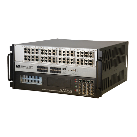
Page 1: User Manual
OP5700 RCP/HIL/ FPGA-BASED REAL-TIME SIMULATOR USER MANUAL www.opal-rt.com... - Page 2 Published by OPAL-RT Technologies, Inc. 1751 Richardson, suite 2525 Montréal (Québec) Canada H3K 1G6 www.opal-rt.com © 2018 OPAL-RT Technologies, Inc. All rights reserved Printed in Canada...
-
Page 3: Symbol Definitions
CAUTION: Indicates a potentially hazardous situation which, if not avoided, may result in minor or moderate injury. It may also be used to alert against unsafe practices. WARNING: Indicates a potentially hazardous situation which, if not avoided, could result in serious injury or death. OP5700 User Manual OPAL-RT Technologies... -
Page 5: Table Of Contents
COnneCtinG netwOrK CaBleS ......................19 I/O CONFIGURATIONS ......................... 20 DB37F CONNECTORS ........................20 PIN ASSIGNMENTS .......................... 22 SPECIFICATIONS ..........................23 OP5700 SPECIFICATIONS ........................ 23 LIMITED WARRANTY ..........................24 liMited warrantY .............................24 retUrn pOliCY ............................24 eXClUSiOnS ..............................24 warrantY liMitatiOn and eXClUSiOn ....................25 diSClaiMer OF UnStated warrantieS ....................25... -
Page 7: Receiving And Verification
After opening the package, remove the equipment and components. Make sure that all the items described in “Standard Hardware” are actually in the box and are undamaged. STANDARD HARDWARE The OP5700 real-time simulator includes the following basic hardware: Item Description... -
Page 8: Introduction
1 The CPU configuration and the use of riser boards for PCI cards may limit the number of available slots, as described in the Hardware configuration section Restrictions to using MUSE with OPAL-RT board software architecture may apply depending on your application and software configuration. Please contact... - Page 9 Lower section target computer Figure 1: OP5700 simulator architecture The image shown above is used to illustrate the layered and flexible product architecture. Customers should not open the chassis unless under the strick guidance of Technical Support. OP5700 User Manual...
-
Page 10: Configuration Options
Introduction System Interconnection Details CONFIGURATION OPTIONS The OP5700 is available in a number of CPU configurations that are factory configured according to the customer’s processing requirement. Product Configuration Description OP5707-4 OP5700 RCP/HIL Virtex7 FPGA-based Real-Time Simulator - 4 cores (5U, Xeon E5, 4 Cores, 3.0 GHz,... -
Page 11: Hardware Interface
Front Connectors HARDWARE INTERFACE FRONT CONNECTORS Figure 2: OP5700 front panel A. RJ45 connector panels provide connections to monitor signals from mezzanine I/O boards. Each connector is linked to front and back mezzanines on the carrier board. Analog mezzanines (channels 0-15) will use only the first column of connectors. Digital mezzanines will use both columns (channels 0-15 in the first column and channels 16-31 on the second column of connectors). - Page 12 GREEN GREEN Table 2: OP5700 SYNCHRO LEDs *The color of the LED on power on depends on the default FPGA configuration: when the FPGA board is programmed in slave synchronization mode, the LED will be orange; when it is programmed in master mode, the LED will be green.
-
Page 13: Rear Connectors
Caution: these power sources are not isolated. C. Ground screw. The OP5700 may be subjected to EMI when installed in proximity to other devices. Make sure to connect the OP5700 ground to the rack to prevent any EMI related damage to the simulator (see Figure 5) D. -
Page 14: Installation
3. Connect the ground screw as described in the “CONNECTING THE GROUND SCREW” section below 4. Connect the blue RJ45 cable to the Ethernet port on the OP5700 and connect to the same network used by the host PC. Refer to the “Cabling Instructions” and the System Description document delivered with your simulator to locate the connector to be used. -
Page 15: Connect Mini Bnc To Bnc
A = channel 28, B = channel 29, C = channel 30 D = channel 31. CONNECT MINI BNC TO BNC These cables establish connections between OPAL-RT hardware and external monitoring devices. AUTOSET AUTORANGE SAVE/RECALL MEASURE... -
Page 16: Connect The Usba To Usbb Cable
Contact Technical Support for all FPGA programming issues. Connect one end to a Windows PC USB port and the other end to the USB JTAG port on the OPAL-RT simulator, then follow the technical support representative’s instructions to flash the FPGA. -
Page 17: Connect The Loopback Kit
Connect the loopback board to the simulator DB37 Output signal • Connect the other end (DB37 connector) of the flat cable to the simulator DB37 Input signal • Connect the VUser (required to preserve isolation) from the loopback board to the OP5700. SIMULATOR INPUT SIMULATOR... -
Page 18: Connect The Screw Terminal
Refer to the simulator or board user manual for exact pin assignments CONNECT THE OPTICAL FIBER CABLE The optical fiber cable is used to establish synchronization connections between simulators (as shown below) . Figure 11: Connecting synchronization cables OPAL-RT Technologies OP5700 User Manual... -
Page 19: Connecting Network Cables
To simulator To network Figure 12: Connecting network cables See the System Integration document for information about the active port. OP5700 User Manual OPAL-RT Technologies... -
Page 20: I/O Configurations
DB37F Connectors I/O CONFIGURATIONS The OP5700 simulator provides signal conditioning for up to 256 I/Os, which are managed from the FPGA module and are accessible via DB37 and RJ45 connectors in the back and front of the chassis. I/O lines are routed through a carrier board (inside the chassis) that can accept up to 8 signal conditioning modules, which provides greater signal conditioning flexibility. - Page 21 Single-ended output: negative pin is connected to ground. Single-ended input: user’s ground must be connected to the negative pin. Differential output: positive and negative signals must be on positive and negative pins. Differential input: connection must be between the positive/negative pair. OP5700 User Manual OPAL-RT Technologies...
-
Page 22: Pin Assignments
+CH29 -CH29 12-15 28-31 +CH14 -CH14 +CH30 -CH30 +CH15 -CH15 +CH31 -CH31 Vuser 1B* Vrtn 1B* Vuser 2B* Vrtn 2B* Table 3: Pin Assignments Vuser and Vrtn signals are only used with digital output modules OPAL-RT Technologies OP5700 User Manual... -
Page 23: Specifications
Operating temperature 10 to 35 ºC (50 to 95ºF) Storage temperature -55 to 85ºC (-67 to 185ºF) Maximum rated ambient 40Cº (104ºF) temperature Relative humidity 10 to 90% non-condensing Maximum altitude 2000 m (6562 ft.) OP5700 User Manual OPAL-RT Technologies... -
Page 24: Limited Warranty
- If the Product is returned for repair more than 12 months after purchase, the Purchaser is responsible for the cost of repair. OPAL-RT will assess the repair and prepare a quote. The RMA number will be sent with the quote. -
Page 25: Warranty Limitation And Exclusion
OPAL-RT Technologies will have no further obligation under this limited warranty. All warranty obligations of OPAL-RT Technologies are void if the Product has been subject to abuse, misuse, negligence, or accident or if the Purchaser fails to perform any of the duties set forth in this limited warranty or if the Product has not been operated in accordance with instructions, or if the Product serial number has been removed or altered. - Page 26 Note CONTACT While every effort has been made to ensure accuracy in this publication, no responsibility OPAL-RT Corporate Headquarters can be accepted for errors or omissions. Data 1751 Richardson, Suite 2525 may change, as well as legislation, and you are Montréal, Québec, Canada...
Need help?
Do you have a question about the OP5700 and is the answer not in the manual?
Questions and answers