
Subscribe to Our Youtube Channel
Related Manuals for Opal-RT OP5650


Summary of Contents for Opal-RT OP5650
- Page 1 OP5600 SERIES V3 Real-Time Digital Simulator OP5650 User Manual Artix 7 www.opal-rt.com...
- Page 2 Published by OPAL-RT Technologies, Inc. 1751 Richardson, suite 2525 Montreal, Quebec, Canada H3K 1G6 www.opal-rt.com ©2018 OPAL-RT Technologies, Inc. All rights reserved Printed in Canada...
- Page 3 CAUTION: Indicates a potentially hazardous situation which, if not avoided, may result in minor or moderate injury. It may also be used to alert against unsafe practices. WARNING: Indicates a potentially hazardous situation which, if not avoided, could result in serious injury or death. OPAL-RT Technologies OP5600/OP5650 User Manual...
-
Page 5: Table Of Contents
INSTALLATION AND CONFIGURATION .................... 10 HARDWARE CONFIGURATION ......................11 ...............................13 back connectors Connecting the Ground Screw ............................14 DB37F CONNECTIONS ........................15 OP5650 DB37 PIN ASSIGNMENTS ....................17 RJ45 CONNECTIONS ........................18 RJ45 CHANNEL ASSIGNMENTS ..................... 19 ...........................20 connecting monitoring devices SPECIFICATIONS ..........................21 FLAT CARRIER SPECIFICATIONS .................... - Page 6 OP5600/OP5650 User Manual OPAL-RT Technologies...
-
Page 7: Receiving And Verification
Disconnect power before servicing The OP5650 may be subjected to EMI when installed in proximity to other devices. Make sure to connect the OP5650 ground to the rack to prevent any EMI related damage to the simulator. OPAL-RT Technologies... -
Page 8: Op5600 Series/Op5650 Simulator
OP5600 SERIES/OP5650 SIMULATOR INTRODUCTION The OP5650 is a complete simulation system, that contains a powerful target computer, a reconfigurable FPGA and signal conditioning for up to 256 I/Os. The design makes it easy to use with standard connectors (DB37, RJ45, SFP and mini-BNC) without the need for input/output adaptors and allows quick connections for monitoring I/O signals. -
Page 9: Simulator Architecture
OP5600 Series/OP5650 Simulator Simulator Architecture SIMULATOR ARCHITECTURE configuration options The OP5650 is available in a number of different configurations that make it easier to integrate into your environment: Product Configuration Description OP5650-4 OP5650 RCP/HIL Artix 7 FPGA-based Real-Time Simulator - 4 cores (4U, Xeon E5, 4 Cores, 3.0 GHz,... -
Page 10: Installation And Configuration
1. Place the OP5650 on a shelf or a desktop, or install in a traditional rack 2. Connect the power cable to the nearest power outlet 3. Connect the OP5650 to the same network used by the host PC, using the cables provided. Figure 2: Top view of mezzanines installed on carrier The top of the chassis can be removed to access the signal conditioning mezzanine boards installed on the carrier board. -
Page 11: Hardware Configuration
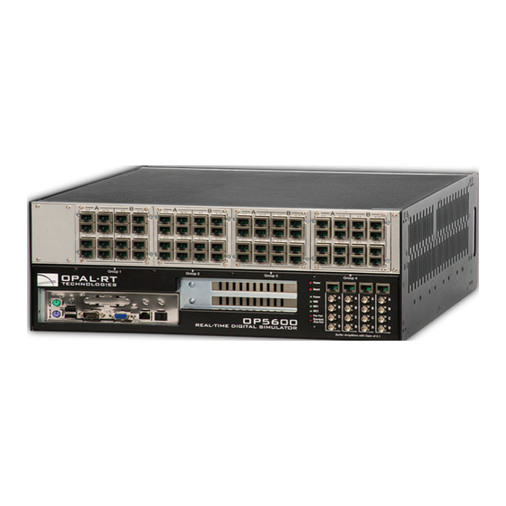
Hardware Configuration HARDWARE CONFIGURATION The interfaces on the front of the OP5650 Artix 7 (OP5143) include 4 RJ45 monitoring panels. Figure 3: OP5650 front connector panels A. 4 panels of RJ45 connectors provide connections to monitor output from mezzanine I/O boards. - Page 12 PCIe boards). E. Standard computer connectors (left to right): mouse and keyboard, USB ports, monitor, network ports. Although use of these connectors is optional but not required to use the OP5650, one network port is required for network connection.
-
Page 13: Back Connectors
Connections”) illustrates the links between the mezzanines and the DB37 I/O connectors B. Ground screw. The OP5650 may be subjected to EMI when installed in proximity to other devices. Make sure to connect the OP5650 ground to the rack to prevent any EMI related damage to the simulator (see Figure 7) C. -
Page 14: Connecting The Ground Screw
Hardware Configuration Connecting the Ground Screw You must connect a grounding cable from the OP5650 ground screw to the rack (or any other strong ground) to ensure that the OP5650 terminates securely in a ground. Proper grounding will help prevent electric shocks, protect the OP5650 from voltage spikes (from a variety of causes, including lightening strikes), and provide increased immunity from EMI by lowering noise levels and emissions. -
Page 15: Db37F Connections
OP5600 Series/OP5650 Simulator DB37F Connections DB37F CONNECTIONS Each pair of mezzanines (A & B) is linked to four female DB37 connectors (I/Os) on the back of the chassis: The first two connectors (left to right) represent channels from Group B, which are linked to the conditioned channels from the back mezzanine. - Page 16 OP5600 Series/OP5650 Simulator DB37F Connections DIGITAL MEZZANINES (top view) OP5600 Rear (DB37) GROUP 1A GROUP 1B GROUP 1B GROUP 1A Connector rear view GROUP 1A GROUP 1B OP5600 Front (RJ45) Figure 7: DB37 connection to mezzanines If the front mezzanine is a digital module (Din or Dout), the first 16 channels (00 to 15) are on the first connector and the next 16 channels (16 to 31) are on the second connector.
-
Page 17: Op5650 Db37 Pin Assignments
OP5600 Series/OP5650 Simulator OP5650 DB37 Pin Assignments OP5650 DB37 PIN ASSIGNMENTS DB37 connector panel silkscreen Connector A Ch. 0-15 Connector A Ch. 16-31 Module pin Module pin Module pin Module pin DB37 DB37 DB37 DB37 assignment assignment assignment assignment +CH00... -
Page 18: Rj45 Connections
OP5600 Series/OP5650 Simulator RJ45 connections RJ45 CONNECTIONS Each RJ45 monitoring panel on the front of the OP5650 simulator connects to front and back mezzanines. The following images illustrate how the mezzanines are linked to the connectors. Top View OP5600 Rear (DB37) -
Page 19: Rj45 Channel Assignments
OP5600 Series/OP5650 Simulator RJ45 channel Assignments RJ45 CHANNEL ASSIGNMENTS Each mezzanine is assigned two columns of RJ45 connectors. Each column represents a series of channels, divided into 4 channels per jack, as shown in Figure 11. SLOT xA SLOT xB... -
Page 20: Connecting Monitoring Devices
RJ45 channel Assignments connecting monitoring devices The OP5650 simulator offers quick, single-ended connections, through RJ45 and mini BNC connectors, to any monitoring device (i.e. oscilloscope, etc.). These mini-BNC jacks let you monitor 4 channels individually. Simply follow these instructions (as illustrated in Figure 12):... -
Page 21: Specifications
OP5600 Series/OP5650 Simulator Flat Carrier Specifications SPECIFICATIONS Product name OP5650 V3 Power supply Universal input and active power factor correction 650W continuous power DC to DC converters for analog voltage Power rating Input : 100-240VAC, 50-60Hz, 10A/5A Power: 600W Input/output power... - Page 22 Limited Warranty OP5650 User Manual OPAL-RT Technologies...
-
Page 23: Limited Warranty
- If the Product is returned for repair more than 12 months after purchase, the Purchaser is responsible for the cost of repair. OPAL-RT will assess the repair and prepare a quote. The RMA number will be sent with the quote. -
Page 24: W Arranty L Imitation And E Xclusion
OPAL-RT Technologies will have no further obligation under this limited warranty. All warranty obligations of OPAL-RT Technologies are void if the Product has been subject to abuse, misuse, negligence, or accident or if the Purchaser fails to perform any of the duties set forth in this limited warranty or if the Product has not been operated in accordance with instructions, or if the Product serial number has been removed or altered. - Page 26 H3K 1G6 recently issued regulations, standards, and Tel.: 514-935-2323 guidelines. Toll free: 1-877-935-2323 This publication is not intended to form the basis of a contract. Technical Services www.opal-rt.com/support UM18-36249 RVN_1.0 12/2018 © OPAL-RT Technologies Inc.
Need help?
Do you have a question about the OP5650 and is the answer not in the manual?
Questions and answers