Table of Contents
Advertisement
Advertisement
Table of Contents

Related Manuals for Opal-RT OP4200


Summary of Contents for Opal-RT OP4200
- Page 1 OP4200 RCP/HIL SYSTEM USER MANUAL www.opal-rt.com...
- Page 2 Published by OPAL-RT Technologies, Inc. 1751 Richardson, suite 2525 Montréal (Québec) Canada H3K 1G6 www.opal-rt.com © 2018 OPAL-RT Technologies, Inc. All rights reserved Printed in Canada...
- Page 3 CAUTION: Indicates a potentially hazardous situation which, if not avoided, may result in minor or moderate injury. It may also be used to alert against unsafe practices. WARNING: Indicates a potentially hazardous situation which, if not avoided, could result in serious injury or death. OP4200 User Manual OPAL-RT Technologies...
-
Page 5: Table Of Contents
Sing tHe OOpbaCk PIN ASSIGNMENTS .......................... 20 TROUBLESHOOTING HARDWARE SETUP ..................21 OP4200 HARDWARE - CASSETTES ....................23 OP4230-1 16 ANALOG OUTPUTS ....................23 featureS ..............................23 deSCriptiOn ..............................23 SCHeMatiCS ..............................23 tYpiCal appliCatiOnS ..........................24 OP4240-1 16 ANALOG INPUTS ......................25 featureS ..............................25... - Page 6 ..............................27 interfaCeS ..............................27 tYpiCal appliCatiOnS ..........................28 OP4260-1 32 DIGITAL OUTPUTS ...................... 29 featureS ..............................29 Recommendations ................................ 29 OP4200 HARDWARE SPECIFICATIONS ..................... 30 OP4200 GENERAL SPECIFICATIONS ....................30 Op4230-1 SpeCifiCatiOnS .........................31 Op4240-1 SpeCifiCatiOnS .........................32 Op4242-1 SpeCifiCatiOnS ..........................33 Op4250-1 SpeCifiCatiOnS ..........................34 Op4260-1 SpeCifiCatiOnS ..........................35...
-
Page 7: Description
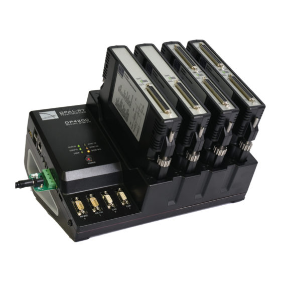
I/O Configurations DESCRIPTION The OP4200 is part of the OPAL-RT line of simulation systems. It contains a SoC (system on chip) integrating an ARM CPU and a Kintex™-7 FPGA, a high-end FPGA, signal conditioning for up to 128 I/O lines and 2 high-speed fiber-optic SFP ports. The design provides four slots for signal conditioning cassettes. -
Page 8: System Interconnection Details
OP5607). The simulator ARM CPUs are then used only for monitoring the unit, and not during the real-time simulation. 1 Restrictions to using MUSE with OPAL-RT Board software architecture may apply depending on your application and software configuration. Please contact your sales representative or field application engineer to verify compatibility... -
Page 9: Op4200 Hardware
USB - Serial Cable Includes DB9M-USB A Male, T00-0814 DB9, F/F, null modem mini type T00-0994 Converts serial connection to USB to interface OP4200 with computer Power Supply Desktop AC Adapter 60W 24V T00-4387 pluggable terminal blocks 4 pos T00-0509... -
Page 10: Hardware Interface
“DIP Switch Configurations” processor. (see for detailed information) H. Ground connector screw: attach grounding wire to nearest ground when using OP4200 in high risk environments. The OP4200 may be subject to EMI when installed in proximity to other devices OPAL-RT strongly recommends the use of anti-static wrist straps whenever handling any electronic device provided by OPAL-RT. -
Page 11: Front Connectors
OPAL-RT Board driver via allows the user to make the unit a slave) B. RS232 connectors. Allow a direct connection to the host computer to display the “OP4200 System Configuration” IP address modification interface. C. CAN connectors: CAN 2.0A, 2.0B, and ISO 118981-1 standard compliant D. -
Page 12: Cassettes
OP4200 Hardware Cassettes CASSETTES There are 4 cassettes slots, labeled 1 to 4, in the OP4200. The OP4200 standard configuration includes the following four cassettes: Slot 1: OP4240-1, 16 analog inputs Slot 2: OP4230-1, 16 analog outputs Slot 3: OP4250-1, 32 digital inputs Slot 4: OP4260-1, 32 digital outputs. -
Page 13: Basic Installation
Disconnect power before servicing. The OP4200 may be subjected to EMI when installed in proximity to other devices. Make sure to connect the OP4200 to the nearest ground to prevent any EMI related damage to the simulator. GENERAL CABLING INSTRUCTIONS The OP4200 provides a number of connectors that each allow users a specific interaction with the unit. -
Page 14: Connecting The Ground Screw
OP4200 ground screw to ensure that it terminates securely in a ground. Proper grounding will help to prevent electric shocks, protect the OP4200 from voltage spikes (from a variety of causes, including lightning strikes), and provide increased immunity from EMI by lowering noise levels and emissions. -
Page 15: Initial Setup
Initial Setup INITIAL SETUP Although the OP4200 is configured to function right out of the package, there are a few configurations that may be necessary (or desired) based on your network setup or according to your specific parameters. This section deals with how to modify those parameters before you proceed to using your OP4200. -
Page 16: Changing The Ip Address
IP address for your OP4200. The best way to do this is to directly connect your OP4200 to your host computer (laptop, etc.). (Be sure to contact your IT department to obtain a valid IP address from them). - Page 17 OP4200 Hardware Initial Setup Figure 8: Starting a serial session in MobaXterm c. Select the serial (COM) port to which the OP4200 is connected (it should appear automatically in the list) d. Set the Speed to 115200 e. Click on the “Advanced settings” tab f.
- Page 18 Click OK to return to the main menu. Click 4 Exit and close MobaXterm. Your OP4200 is now ready to use and can be connected to your network. Once it is connected to the network, you should test communication by pinging the OP4200 from your computer...
-
Page 19: Testing Signals Using The Loopback Kit
2. Connect the loopback board to the OP4200 DB37 output cassette 3. Connect the other end (DB37 connector) of the flat cable to the OP4200 DB37 input cassette 4. When this kit is used to test digital signals, connect the Vuser (required to preserve isolation) from the loopback board (connector end) to an external source (wire end). -
Page 20: Pin Assignments
OP4200 Hardware Pin Assignments PIN ASSIGNMENTS Conditioning cassettes come with either one (analog) or two (digital) DB37 connectors. These connectors respect OPAL-RT’s standard DB37 pinout, as shown in the table below. Ch. 00-15 Ch. 16-31 Module pin Module pin Module pin... -
Page 21: Troubleshooting Hardware Setup
TROUBLESHOOTING HARDWARE SETUP Problem Possible Cause Solution Nothing happens when I connect my RS232 cable driver not detected Download driver from http://www. RS232 cable prolific.com.tw/US/ShowProduct. aspx?p_id=225&pcid=41 No serial terminal software detected Install MobaXterm from http:// mobaxterm.mobatek.net/download.html OP4200 User Manual OPAL-RT Technologies... - Page 22 OPAL-RT Technologies OP4200 User Manual...
-
Page 23: Op4200 Hardware - Cassettes
OP4200 HARDWARE - CASSETTES OP4230-1 16 ANALOG OUTPUTS OP4200 HARDWARE - CASSETTES OP4230-1 16 ANALOG OUTPUTS FEATURES • • 16 single-ended analog output channels • • All outputs are sampled simultaneously, up to 1 MS/s • • 16 bit resolution •... -
Page 24: Typical Applications
OP4200 HARDWARE - CASSETTES TYPICAL APPLICATIONS The following diagrams provide an example of a typical application using the OP4230-1. Client Side OP4230-1 Analog Output VDC+ Analog In Signal Conditionning 15 mA max Figure 15: Figure 2: Typical application diagram OPAL-RT Technologies... -
Page 25: Op4240-1 16 Analog Inputs
OP4200 HARDWARE - CASSETTES OP4240-1 16 ANALOG INPUTS OP4240-1 16 ANALOG INPUTS FEATURES • 16 differential analog input channels • All inputs are sampled simultaneously for additional simulation accuracy. They can be sampled up to 400 KS/s • 16 bit resolution •... -
Page 26: Op4242-1 16 Analog Inputs
±20 Volts with no additional resistors. - To ADC 475k 1% 1K0 1% + IN 24K91% 200pF Filter 800kHz 24K91% 200pF - To ADC 1K0 1% 475k1% + IN Figure 17: Differential input ADC circuit OPAL-RT Technologies OP4200 User Manual... -
Page 27: Op4250-1 32 Digital Inputs
Each input has a reverse voltage protection of up to 30 Volts provided by a Schottky diode. Digital Input Isolated User +5VDC Vuser (5 to 30V) to_FPGA OPTIONAL FILTER Vuser_RTN OPTION 1: COMMON ANODE OPTION 2: COMMON CATHODE MODE SELECTION WITH ON-BOARD ZERO-OHM RESISTORS Figure 18: OP4250-1 isolated digital input drawing OP4200 User Manual OPAL-RT Technologies... -
Page 28: Typical Applications
Max. 10 mA MODE 1: COMMON ANODE Figure 19: Both Din + and Din - are available to the user TYPICAL APPLICATIONS The diagrams below illustrate typical application examples. INTERFACE BETWEEN CMOS DRIVE AND OPAL-RT Din OPAL-RT Din User +2.5V/+3.3V TC4049/4050... -
Page 29: Op4260-1 32 Digital Outputs
Device Under Test) to minimize ringing and over/undershoot according to the connection length (from OP4260-1 to user device). The following parameters are a good starting point for the RC values: R=150Ω , C = 100pF. Tuning is necessary, according to application parameters. OP4200 User Manual OPAL-RT Technologies... -
Page 30: Op4200 Hardware Specifications
OP4200 Hardware Specifications OP4200 General Specifications OP4200 HARDWARE SPECIFICATIONS OP4200 GENERAL SPECIFICATIONS Product name OP4200 ARM® Processor dual-core Cortex A9 1GHz (1000MHz optional) Memory 16 GB SD card, 1024 MB SRAM Linux-based real-time operating system FPGA Xilinx Zynq®XC7Z030, Kintex™-7 FPGA, 125K LUT... -
Page 31: Op4230-1 Specifications
OP4200 Hardware Specifications OP4200 General Specifications OP4230-1 SPECIFICATIONS Product Name OP4230-1 Part Number 126-0157 Number of channels 16 single-ended Resolution 16 bits Default range ± 16 Volts Maximum current 15 mA Max. Sampling Frequency 1 MS/s Min Conversion / Acquisition Time 1 μs per channel... -
Page 32: Op4240-1 Specifications
OP4200 Hardware Specifications OP4200 General Specifications OP4240-1 SPECIFICATIONS Product Name: OP4240-1 Number of channels: OP4240-1: 16 differential Resolution: 16 bits Max. Sampling Frequency: 500 kS/s Min Conversion / Acquisition Time: 2.5 μs per channel ADC Type: 8 x Dual ADC with 10 MBit/s Serial Output Transfer... -
Page 33: Op4242-1 Specifications
Resolution 16 bits Ω Input impedance Max. Sampling Frequency 2 MSPS Min Conversion / Acquisition Time 510 nanoseconds per channel on OP4200 ADC Type 8 x Dual ADC Input voltage range ± 20V Bandwidth Small signal (-3 dB): 400 kHz Accuracy ±10mV on the entire ±20V range... -
Page 34: Op4250-1 Specifications
OP4200 Hardware Specifications OP4200 General Specifications OP4250-1 SPECIFICATIONS Product name OP4250-1 (32 opto-isolated digital inputs) Number of channels 32 digital inputs Isolation Optical isolator Connection mode Anode and cathode available on connector Input current 3.6 mA, current limiting diode Reverse voltage protection... -
Page 35: Op4260-1 Specifications
OP4200 Hardware Specifications OP4200 General Specifications OP4260-1 SPECIFICATIONS Product name OP4260-1 (32 digital outputs - push-pull) Number of channels 32 digital outputs 2 banks of 16, fully isolated and independant of each other Isolation Galvanic isolator Output Protection 50 mA resettable fuse Protection thresholds Over voltage: 30V ±5%... -
Page 36: Limited Warranty
- If the Product is returned for repair more than 12 months after purchase, the Purchaser is responsible for the cost of repair. OPAL-RT will assess the repair and prepare a quote. The RMA number will be sent with the quote. -
Page 37: Warranty Limitation And Exclusion
OPAL-RT Technologies will have no further obligation under this limited warranty. All warranty obligations of OPAL-RT Technologies are void if the Product has been subject to abuse, misuse, negligence, or accident or if the Purchaser fails to perform any of the duties set forth in this limited warranty or if the Product has not been operated in accordance with instructions, or if the Product serial number has been removed or altered. - Page 38 Note CONTACT While every effort has been made to ensure accuracy in this publication, no responsibility OPAL-RT Corporate Headquarters can be accepted for errors or omissions. Data 1751 Richardson, Suite 2525 may change, as well as legislation, and you are Montréal, Québec, Canada...
Need help?
Do you have a question about the OP4200 and is the answer not in the manual?
Questions and answers