Advertisement
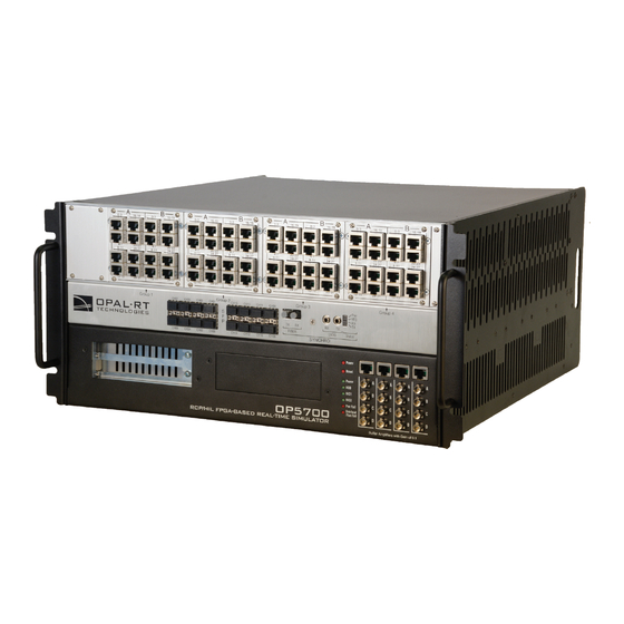
OP5700 Installation and Configuration
Connecting the Ground Screw
Follow this simple installation procedure. Make sure to respect proper grounding,
1. Place the OP5700 on a shelf, desktop, or install in a traditional rack
2. Connect the power cable to the nearest power outlet
3. Connect the ground screw as described in the "CONNECTING THE GROUND SCREW" section
4. Connect the blue RJ45 cable to the Ethernet port on the OP5700 and connect to the same network used by the host PC.
OPAL-RT strongly recommends the use of anti-static wrist straps whenever handling any electronic device provided by OPAL-RT.
Disconnect power before servicing.
OPAL-RT simulators and hardware devices may be subjected to electromagnetic interference (EMI) when installed in proximity to
other devices. Make sure to connect the ground to the rack or strong earth to prevent any EMI related damage to the simulator.
Connecting the Ground Screw
You must connect a grounding cable from the OP5700 ground screw to ensure that it terminates securely in a ground. Proper grounding helps to prevent
electric shocks, protects the OP5700 from voltage spikes (from a variety of causes, including lightning strikes), and provides increased immunity from EMI
by lowering noise levels and emissions.
Select a flat braided grounding strap of adequate length (as short as possible provides the best protection), with ring terminals on each end.
Attach one ring terminal to the ground screw on the OP5700 (shown in the figure below).
Attach the other ring terminal to the rack using a nut and lock washer.
Advertisement
Table of Contents

Related Manuals for Opal-RT OP5700


Summary of Contents for Opal-RT OP5700
- Page 1 Connecting the Ground Screw You must connect a grounding cable from the OP5700 ground screw to ensure that it terminates securely in a ground. Proper grounding helps to prevent electric shocks, protects the OP5700 from voltage spikes (from a variety of causes, including lightning strikes), and provides increased immunity from EMI by lowering noise levels and emissions.
- Page 2 Connect the loopback board to the simulator DB37 Output signal Connect the other end (DB37 connector) of the flat cable to the simulator DB37 Input signal Connect the VUser (required to preserve isolation) from the loopback board to the OP5700...
- Page 3 Note: Although some boards do provide a power source, using that would compromise the isolation. OPAL-RT recommends using external power source: the user must connect the power wires (provided) to either a 5 or 12 V power source. Make sure that the Vuser source switch on the loopback board is set to “External”.
- Page 4 Technical Support for all FPGA programming issues. Connect one end to a Windows PC USB port and the other end to the USB JTAG port on the OPAL-RT simulator, then follow the technical support representative’s instructions to reprogram the FPGA.
Need help?
Do you have a question about the OP5700 and is the answer not in the manual?
Questions and answers