Advertisement
Read these instructions before placing unit in service.
Keep these and other materials with the unit in a binder near the machine for easy reference by supervisors and operators
Installation—Operation—Maintenance
Operation Manual
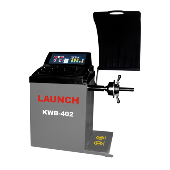
KWB-402
Wheel Balancer
*Read these instructions
before placing unit in ser-
vice.
**Keep these and other ma-
terials with the unit in a
binder near the machine for
easy reference by supervi-
sors and operators.
***You will need the man-
ual for the information of
the machine, such as safety
warning and precautions,
assembly, operating, main-
tenance and parts list / as-
sembly diagrams.
****Keep
your
invoice
with this manual for future
reference.
Manufacturer
shall not be liable for any
injury to persons on damage
to thins caused by failure to
comply with these regula-
tions and can cancel war-
ranty coverage.
Advertisement

Related Manuals for Launch KWB-402


Summary of Contents for Launch KWB-402
- Page 1 Operation Manual KWB-402 Wheel Balancer *Read these instructions before placing unit in ser- vice. **Keep these and other ma- terials with the unit in a binder near the machine for easy reference by supervi- sors and operators. ***You will need the man-...
-
Page 2: Table Of Contents
Table of Contents Specification Table …………………………….………….…………….3 Safety Instructions……………………………………………….………4 Installation and assembly …………………………………….……….7 Control panel ………………………………………………….………….9 Wheel Mounting ………………………………………………………….10 Wheel Data entry………………………………………………………….12 Calibration…………………………………..……………...….……..14 Wheel balancing …………………………………………..……………..15 Trouble shooting ………………………………………………………..19 Maintenance…………………………………………………..…………19 Assembly Diagram…………………………………………………….. Part list……………………………………………………………….….. Wiring Diagram……………..…………………………………...…... -
Page 3: Specification Table
1.Specification Table Item Description Electrical Requirements See the manufacturer’s Serial plate For Most Passenger Car And Light Truck Product Compatibility Wheels Maximum Tire Diameter Capacity 31.5”/800mm Maximum Tire Width Capacity 20” Minimum/ Maximum Rim Diameter Capacity 10″-20″ Minimum/ Maximum Rim Width Capacity 1.5″-20″... - Page 4 2.Operator Protective Equipment Personal protective equipment helps make tire servicing safer. However, equipment does not take the place of safe operating practices. Always wear durable work clothing during tire service activity. Loose fit- ting clothing should be avoided. Tight fitting leather gloves are recommended to protect operator’s hands when handling worn tires and wheels.
-
Page 5: Safety Instructions
4.SAFETY INSTRUCTION GENERAL SAFETY WARNINGS AND PRECAUTIONS 4.1.1 KEEP WORK AREA CLEAN AND DRY. Cluttered, damp, or wet work are-as invite inju- ries. KEEP CHILDREN AWAY FROM WORK AREA. Do not allow children to handle this product. STORE IDLE EQUIPMENT. When not in use, tools and equipment should be stored in a dry lo- cation to inhibit rust. - Page 6 SPECIFIC PRODUCT WARNINGS AND PRECAUTIONS Make sure this machine is used on a dry, flat, level, oil/grease free, concrete sur- face capable of supporting the weight of the Wheel Balancer, the tire being bal- anced, and any additional tools and equipment. Before each use, always examine the wheel balancer for structural cracks and bends, damage to the safety guard and electrical wiring, and any other condition that may affect the safe operation of the machine.
-
Page 7: Installation And Assembly
4.2.14 WARNING: This product contains or produces a chemical known to the State of California to cause cancer and birth defects (or other reproductive harm). (California Health & Safety Code 25249.5 et seq.) WARNING: People with pacemakers should consult their physician(s) before using this product. - Page 8 3.Move the Wheel Balancer back to the desired location, and align the three ma-chine mount- ing holes at the base of the Body with the three previously drilled floor anchor holes. If necessary, level the Wheel Balancer by inserting steel shims between the base of the ma- chine and the concrete floor surface.
-
Page 9: Control Panel
7. Control Panel FIGURE 1 DISPLAYS IDENTIFICATION 14INNER side display window, indicates readings of balancing weight to be attached on In- ner side of wheel. 15OUTER side display window, indicates readings of balancing weight to be attached on outer side of wheel. 13 Weight Position LEDs for INNER side- Full LEDs flash when correct weight position is at top-dead-center. - Page 10 9 ALU Key-Press to select desired balancing mode. 7 Key- Press to recalculate weight amount to be attached to the wheel; Or hold this key to perform Calibration (see the chapter of calibration). 1Wheel offset (a) enter keys –press to enter wheel offset a( The distance between the inner rim flange and the edge of the balancer.) 2Rim Width (b) enter keys –press to enter rim width b 3Rim diameter (d) enter keys –press to enter rim diameter d...
-
Page 11: Wheel Data Entry
8.4 Hold the Adjustable Nut (part #16) with both hands. While doing so, use your thumb to move the Thumb Lock on the Adjustable Nut to the right. While holding the Thumb Lock in position, slide the Adjustable Nut onto the Trans-mission Shaft (part #24) and firmly against the Cone (part #18). - Page 12 9.2 Enter rim width b Open the calipers wide enough to reach around the tire. Close the calipers so both tips contact the rim flanges. Read the rim width on the calipers. As shown in the following figure. Enter rim width b by using the rim width keys (each pressing value will be added or deducted as following table indicated.) Table : Value variation for rim width b.
- Page 13 Put extension rod on the rim distance pointer as shown in the above figures. Use the same method mentioned above, take reading from the distance gauge. Release the rim distance pointer to home position, enter the wheel offset a value (a=the above mention reading +6) The procedure to enter rim diameter d and rim width b are described in the section 5.2.and 9.5 Rim data entry for ALU-s mode.
-
Page 14: Calibration
10. Procedure of system calibration and parameter setting 10.1 Balancing calibration Important: Calibration is needed when: a)First time operation; b) Incorrect test result suspected. The procedure of calibration: Put a medium size wheel, mount on the shaft and lock it well. Input the data of the rim. Press and hold the key [F] and key [C]. - Page 15 11. Balancing a Wheel. 11.1 Procedure for passenger car wheels and light truck wheels. Switch on power, mount the wheel, enter rim data. Put down protective cover, press key [START]. The wheel start spinning, and after spin ended, the amount of weights need to attached on the rim will be displayed on the INEER and OUTER display window.
-
Page 16: Wheel Balancing
Weight Recalculation . Re-enter rim data, without spinning wheel, press Key [C], the recalculated balancing weights are displayed on the windows. To display actual imbalance weight less than 5 gram. For the reason that the available standard weights in- terval is 5 gram, increased by every 5 gram, so even after balance weight attached on the rim , there might be weight below 4 gram not balanced, to know how much of it, press key [FINE], the actual imbalance weight re- mained (1~4 grams) can be indicated. - Page 17 ALU-2 mode: weight to be attached inside the rim. As illustrated in the following figure. ALU-2 mode ALU-3 mode: INNER weight to be attached (clipped on) on the edge of rim, and OUTERweight to be stuck inside the rim. As illustrated in the following figure. ALU-3 mode 11.5 ALU-s mode.
- Page 18 12. Optimize balancing function This function is recommended only when static balancing value over 30 grams, to optimize the balancing and reduce weight to be added. 12.1 To get the best result, proceed the following procedure carefully. Press key [OPT], the display reads: [OPT] [ ], Press [START] to activate a spin cycle, with the spinning finished, the display reads:...
-
Page 19: Trouble Shooting
13. Trouble shooting. Machine failure can be detected and identified by the system, and display on the windows with Err codes. The following table indicates the Err code and the definitions. Error Code Definition Err1 Rotation signal failure possible causes Motor failure Position location error Sensor broken... - Page 20 weights, tools, etc, and remove the Tool Tray from the rest of the machine. Loosen the four Nuts so that the Motor may be moved horizontally forward and backward. To tighten the tension, move the Motor backward until the Pulley Belt is tight to the touch and re- tighten the four Nuts.
Need help?
Do you have a question about the KWB-402 and is the answer not in the manual?
Questions and answers
Boa tarde essa maquina liga e enseguida aparece a mensagem off, quais as causas provavel??
The possible causes for the Launch KWB-402 machine to turn on and then display the message "off" are not explicitly listed in the provided context. Therefore, the specific reason for this behavior cannot be determined from the available information.
This answer is automatically generated