Table of Contents
Advertisement
Advertisement
Table of Contents

Related Manuals for Launch X-631


Summary of Contents for Launch X-631
-
Page 2: Table Of Contents
X-631/X-631+ Installation and Parts Manual LAUNCH Table of Contents Precautions for Operation................................1 Unpacking....................................2 Remove Cabinet Box................................2 Remove the Accessory Box..............................2 Installation and Adjustment...............................3 Install the Main Unit ..................................3 Adjustment of the Main Unit ..............................3 Link Adjustment ..................................3 Structure......................................4 Overall Structure..................................4 Main Unit ....................................5... -
Page 3: Precautions For Operation
If the power voltage is not stable, please purchase and use AC voltage stabilizer. X-631/X-631+ is operated with image sensing. Do not stop the light beam between sensors. Avoid reflection light of the ground and direct light to the probe rod while testing. -
Page 4: Unpacking
Unpacking LAUNCH Unpacking X-631/X-631+ is delivered to the customers in two cartons: a cabinet box and an accessory box. Remove Cabinet Box The cabinet box is 690mm×726mm×1295mm in size. There is a PC set (including host computer and monitor), keyboard, mouse, RF main emitter and receiver box etc. -
Page 5: Installation And Adjustment
Put the brake pedal depressor between the brake pedal and the driver seat to keep the brake applied. Restart the computer and enter the WINDOWS2000 operating system. Click the icon of X-631or X-631+ Wheel Aligner program to run the program. The screen will display the main function menu. Please read the user’s manual for... -
Page 6: Structure
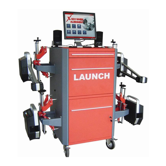
LAUNCH Structure Overall Structure The X-631/X-631+ wheel aligner mainly consists of main unit, probe rods, wheel clamps, turntables, steering wheel holder and brake pedal depressor, etc. as shown in the Fig.3.1. Fig.3.1 1— main unit, 2—RL probe rod assembly, 3—FL probe rod assembly, 4—FR probe rod assembly, 5—RR probe rod... -
Page 7: Main Unit
Probe Rods X-631/X-631+ is equipped with four probe rods. They are FL, RL, FR and RR probe rods, as shown in Fig.3.3. The front probe rods can be cross interchanged with the rear probe rods at the same time, but cannot be changed. If one of the probe rods is changed, it is only necessary to calibrate the changed probe rod, and the other three probe rods needn’t to be... -
Page 8: Wheel Clamp Hanging Brackets
Fig.3.4 Wheel Clamp Hanging Brackets X-631/X-631+ wheel aligner is equipped with 4 wheel clamp hanging brackets as shown in Fig.3.5. Fig.3.5 After unpacking, it is necessary to install these 4 hanging brackets on left and right side wall of the cabinet. -
Page 9: Steering Wheel Holder
When using the electronic turn table, connect its connecting cable to 3PIN socket in the middle of the front left or front right probe rod. Steering Wheel Holder X-631/X-631+ has a steering wheel holder as shown in Fig.3.7. Use the steering wheel holder to lock the steering wheel according to the tips on the screen. Fig.3.7 Steering wheel holder Brake Pedal Depressor X-631/X-631+ has a brake pedal depressor as shown in Fig.3.8. -
Page 10: Part List
RL probe rod assembly 206010347 RR probe rod assembly 206010347 Wheel clamp 103250180 Wheel clamp hanging bracket Y201021815 Mechanical turntable 103202189 User’s manual of X-631/X-631+ wheel aligner 107010839 Installation parts manual X-631 107010840 &X-631+wheel aligner X-631/X-631+ wheel aligner Quick Start Guide 107010940... - Page 11 RL probe rod assembly 206010347 RR probe rod assembly 206010347 Wheel clamp 103250180 Wheel clamp hanging bracket 103260232 Mechanical turntable 103202189 User’s manual of X-631/X-631+ wheel aligner 107010839 Installation parts manual X-631 107010840 &X-631+wheel aligner X-631/X-631+ wheel aligner Quick Start Guide 107010940...
Need help?
Do you have a question about the X-631 and is the answer not in the manual?
Questions and answers