Table of Contents
Advertisement
Meridian 1
Attendant Consoles
Description
Document Number: 553-2201-117
Document Release: Standard 10.00
Date: January 2002
Year Publish FCC TM
Copyright © 1989 – 2002 Nortel Networks
All Rights Reserved
Printed in Canada
Information is subject to change without notice. Nortel Networks reserves the right to make changes in design
or components as progress in engineering and manufacturing may warrant. This equipment has been tested
and found to comply with the limits for a Class A digital device pursuant to Part 15 of the FCC rules, and the
radio interference regulations of Industry Canada. These limits are designed to provide reasonable protection
against harmful interference when the equipment is operated in a commercial environment. This equipment
generates, uses and can radiate radio frequency energy, and if not installed and used in accordance with the
instruction manual, may cause harmful interference to radio communications. Operation of this equipment in a
residential area is likely to cause harmful interference in which case the user will be required to correct the
interference at their own expense.
SL-1 and Meridian 1 are trademarks of Nortel Networks
Advertisement
Table of Contents

Related Manuals for Nortel Meridian M1250


Summary of Contents for Nortel Meridian M1250
- Page 1 All Rights Reserved Printed in Canada Information is subject to change without notice. Nortel Networks reserves the right to make changes in design or components as progress in engineering and manufacturing may warrant. This equipment has been tested and found to comply with the limits for a Class A digital device pursuant to Part 15 of the FCC rules, and the radio interference regulations of Industry Canada.
- Page 3 Page 3 of 64 Revision history January 2002 Standard 10.00. This document is up-issued to include content changes for Meridian 1 Internet Enabled Release 25.40. April 2000 Standard 9.00. This is a global document and is up-issued for X11 Release 25.0x.
- Page 4 Page 4 of 64 December 1990 This document is reissued to include updates and changes for X11 Release 16.0x. December 1989 Revised to incorporate corrections and updated information. July 1989 Removed all references to MJ1250 console. February 1989 Standard for M1250 Console issued. 553-2201-117 Standard 10.00 January 2002...
-
Page 5: Table Of Contents
Page 5 of 64 Contents About this document ..... . . Introduction ....... Reference list . - Page 6 Page 6 of 64 Contents Attendant console operation ....Contents ..........Reference list .
- Page 7 Contents Page 7 of 64 Semi-Automatic Camp-On ....... Series Call ..........Powering and reset .
- Page 8 Page 8 of 64 Contents 553-2201-117 Standard 10.00 January 2002...
-
Page 9: About This Document
Page 9 of 64 About this document This document is a global document. Contact your system supplier or your Nortel Networks representative to verify that the hardware and software described are supported in your area. Attendant Consoles Description... - Page 10 Page 10 of 64 About this document 553-2201-117 Standard 10.00 January 2002...
-
Page 11: Introduction
Page 11 of 64 Introduction Reference list The following are the references in this section: • Equipment Identification (553-3001-154) • Meridian 1 Attendant PC: Software User Guide Feature description Attendant consoles are designed to assist in placing and extending calls into and out of a telephone switching system. - Page 12 Page 12 of 64 Introduction • The Meridian 1 Attendant PC Software application allows all functions supported by the M2250 to be performed on a computer workstation using a mouse pointing device or keyboard within a Windows 95® operating system environment. The M2250 attendant console is not required to run the Meridian 1 Attendant PC Software application.
- Page 13 Introduction Page 13 of 64 Table 1 Engineering and ordering codes for the M1250 and M2250 and related equipment Console Engineering Ordering (CPC) Color model code code M1250 NT2G00AC-35 Chameleon A0387385 gray (ash) M1250 NT2G00AA-98 BTS dark gray A0338244 (not available in North America) M2250 NT6G00AF-35...
- Page 14 Page 14 of 64 Introduction The M1250 and M2250 have the following features: • A four-line, 40 character, liquid crystal display (LCD) with backlighting. Power, including backlighting, is maintained during building power failures with the Meridian 1 battery backup, if equipped. A two-line, 23 character, liquid crystal display (LCD) with backlighting (M2250 only).
- Page 15 Introduction Page 15 of 64 • Time and date system download on the M2250. • Alert tone volume and frequency selection. • Electret or carbon transmitter support. • Power Fail Transfer switch. • Keyclick (M2250 only). Attendant Consoles Description...
- Page 16 Page 16 of 64 Introduction 553-2201-117 Standard 10.00 January 2002...
-
Page 17: Description
Page 17 of 64 Description Contents This section contains information on the following topics: Feature description ........Physical details . -
Page 18: Feature Description
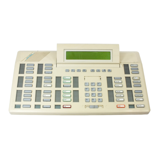
Page 18 of 64 Description Feature description Figure 1 on page 19 and Figure 2 on page 20 show top views of the layouts of the M1250 and M2250 attendant consoles, respectively. The user-accessible components are labeled using a row/column grid arrangement. - Page 19 Description Page 19 of 64 Figure 1 M1250 attendant console – top view Attendant Consoles Description...
- Page 20 Page 20 of 64 Description Figure 2 M2250 attendant console – top view 553-2201-117 Standard 10.00 January 2002...
- Page 21 Description Page 21 of 64 Figure 3 M1250 and M2250 attendant consoles – rear, left side, and bottom views Display panel (can be tilted upwards) Handset/Headset jacks Handset/Headset jacks Protective plastic cover to be installed when ....connector is not in use ..
-
Page 22: Function Keys
Page 22 of 64 Description Function keys The attendant console has eight function keys, located directly below the display screen. Refer to Table 2 for the positions, functions, and markings of these keys. For an explanation of the functions assigned to the rest of the attendant console keys, refer to “Attendant console operation”... - Page 23 Description Page 23 of 64 Table 2 Softkey definitions and functions (Part 2 of 2) Key number (as shown in Function Figures 1 and 2) Prime function (normal): Scrolls the currently selected line to the right. Level 1 function (Shift): Increases the alert speaker volume.
-
Page 24: Switches
Page 24 of 64 Description Switches A slider control, located below the dial pad, between columns DI/EI and FI, controls the handset and headset receive volume level. See Figures 1 and 2. A Power Fail Transfer (PFT) switch is located in the baseplate. See Figure 3 on page 21. -
Page 25: Display Screen Messages
Description Page 25 of 64 Display screen messages Source information appears on line 2 of the display screen. Destination information appears on line 3 of the display screen. The status messages listed below appear on line 4 of the display screen panel. —... -
Page 26: Local Console Controls
Page 26 of 64 Description The M2250 attendant console is connected to the Meridian 1 through two digital ports (primary and secondary) with three additional ports for powering. The M1250 uses two hybrid ports (primary and secondary) for connection to the Meridian 1, with two additional ports for powering. The M2250 console requires a digital line card or an Integrated Services Digital Line Card (ISDLC) of vintage D or later. -
Page 27: Busy Lamp Field/Console Graphics Module
Description Page 27 of 64 Busy Lamp Field/Console Graphics Module The Busy Lamp Field/Console Graphics Module (BLF/CGM) can be added to an M1250 or M2250 attendant console. The BLF/CGM can do the following: • display the status (busy or idle) of up to 150 consecutive extensions within the Meridian 1 Standard Busy Lamp Field (SBLF) •... -
Page 28: Power Requirements
Page 28 of 64 Description Power requirements The BLF/CGM obtains its power through the attendant console. To provide backlighting for the BLF/CGM display, an external floating 16 V dc (300 mA) power supply (A0367601) must be cabled in at the local Main Distribution Frame (MDF) at a maximum of 35 m (115 ft) from the attendant console. -
Page 29: Attendant Console Operation
Page 29 of 64 Attendant console operation Contents This section contains information on the following topics: M1250/2250 configurations ....... . . QMT2 feature disabled . - Page 30 Page 30 of 64 Attendant console operation Emergency Transfer ........Attendant Administration .
-
Page 31: M1250/2250 Configurations
Attendant console operation Page 31 of 64 M1250/2250 configurations The M1250 and M2250 attendant consoles can be configured to operate with the QMT2 feature, which is provided by a QMT2 add-on module incorporated in the console. Instead of having to add a keystrip unit, the technician can set a dip switch on the keyboard/controller Printed Circuit Panel (PCP) to ON (enable QMT2) or OFF (disable QMT2). -
Page 32: Qmt2 Feature Enabled
Page 32 of 64 Attendant console operation QMT2 feature enabled When the QMT2 feature is enabled, the following conditions apply: • If the console is not in Shift mode, the keys in strip AK and/or BK function as Incoming Call Identification (ICI) keys. •... -
Page 33: M1250/2250 Feature Key Modes
Attendant console operation Page 33 of 64 • hard disk with at least 4 MB free disk space • 17-inch color monitor (SVGA recommended) • MPC-2 16 bit sound board • Network interface adapter For complete installation and operation instructions, refer to the Meridian 1 Attendant PC Installation Guide and Meridian 1 Attendant PC User Guide. - Page 34 Page 34 of 64 Attendant console operation Table 1 Softkey alternate functions Operational mode Function Normal Selects line 2 of the display for scrolling. Normal Scrolls left on the selected line, at 8 characters per step. Normal Scrolls right on the selected line, at 8 characters per step.
-
Page 35: M1250/2250 Console Diagnostics
Attendant console operation Page 35 of 64 M1250/2250 console diagnostics Use the Diagnostics menu to check the functions of the console and to perform tests. To enter the Diagnostics mode, use the following procedure. Figure 5 shows the main Diagnostics menu for the M1250 and M2250 attendant consoles. - Page 36 Page 36 of 64 Attendant console operation Keyboard Use this procedure to check the functionality of each key on the console. When a key is pressed, its location code is displayed within parentheses. For example, (00) denotes the upper left-hand ICI key. From Diagnostics menu 1, press “1.”...
- Page 37 Attendant console operation Page 37 of 64 Lamps Use this procedure to check the functionality of each LCD indicator on the console. From the Diagnostics menu 1, press “2.” Press 1 to turn all lamps ON. Press the asterisk (*) to turn each lamp OFF one by one.
- Page 38 Page 38 of 64 Attendant console operation Lamp Field Use this procedure to check the functionality of the Busy Lamp Field/Console Graphics Module. Once in this menu, the dial pad is in CGM mode. When any dial pad keys are pressed, except the pound (#) key, the keys are echoed on the BLF/CGM Module.
- Page 39 Attendant console operation Page 39 of 64 Firmware Use this procedure to display the release and issue numbers of the firmware installed on the UIP and ASIP microprocessor boards. From Diagnostics menu 2, press “2.” The display shows the firmware release and issue numbers, as shown below: DIAGNOSTICS: FIRMWARE...
- Page 40 Page 40 of 64 Attendant console operation Press key “2” to toggle the secondary control gate between ON and OFF. Press key “3” to toggle the attendant receive control between ON and OFF. Press key “4” to toggle the attendant transmit control between ON and OFF.
-
Page 41: M1250 Failure Codes
Attendant console operation Page 41 of 64 M1250 failure codes A failure code will appear on the display screen in response to the detection of a hardware fault. Refer to Table 3 for an explanation of failure codes and possible solutions. Table 3 M1250 failure codes (Part 1 of 2) Failure code... - Page 42 Page 42 of 64 Attendant console operation Table 3 M1250 failure codes (Part 2 of 2) Failure code Reason What to do A key in column E is stuck. Same as for 08H. A key in column F is stuck. Same as for 08H.
-
Page 43: M2250 Failure Codes
Attendant console operation Page 43 of 64 M2250 failure codes A failure code appears on the display in response to the detection of a hardware fault. Refer to Table 4 for an explanation of failure codes and possible solutions. Table 4 M2250 failure codes (Part 1 of 2) Printed Failure... - Page 44 Page 44 of 64 Attendant console operation Table 4 M2250 failure codes (Part 2 of 2) Printed Failure circuit Reason What to do code pack (PCP) A key in column D1 is Same as for 08H. stuck. A key in column D2 is Same as for 08H.
- Page 45 Attendant console operation Page 45 of 64 The failure codes produced by the firmware in response to the detection of a hardware fault are bit-significant as follows: KEYS ASIP RS-232 A44#3 A44#2 A44#1 UART * Refers to key’s column number. Note: Bit 7 indicates whether the failure occurred on the user interface printed circuit card (UIP) (B7=0) or on the audio and system interface printed circuit card (ASIP) (B7=1).
-
Page 46: Attendant Console Features
Page 46 of 64 Attendant console operation Attendant console features Time and date On the M2250 only, the time and date are automatically downloaded from the Meridian 1 on power-up or console reset. To set the time and date locally on the M1250 attendant consoles, follow the procedures in Tables 5 and 6. -
Page 47: Trunk Group Busy Indicators
Attendant console operation Page 47 of 64 Table 6 Setting the date (M1250) Step Action Response Press the Shift key. Press F1 to enter the Options menu. Select option 5 (set date). The current date appears in the day-month-year format. To exit without changing the date, press the octothorpe (#) key. -
Page 48: Incoming Call Indicators
Page 48 of 64 Attendant console operation Note: The M2250 attendant console must be equipped with the Attendant Supervisory Module (NT7G10AA) to allow attendant supervision. Incoming Call Indicators Incoming Call Indicators (ICIs) display the various types of incoming calls presented to the attendant console. They also indicate the number of calls, and the length of time calls have been queued. -
Page 49: Attendant Blocking Of Dn
Attendant console operation Page 49 of 64 The customer will also be able to define whether Night Call Waiting tone will be given to Night stations. With Night Call Waiting tone allowed, busy Night stations are notified when an incoming call is terminating on them. The incoming call will be queued on the Night station until it becomes idle. -
Page 50: Network Attendant Services
Page 50 of 64 Attendant console operation Refer to Networking Features and Services (553-2901-301) for further details. Network Attendant Services This feature allows attendant services to be distributed anywhere within a Meridian ISDN network. If, at the time of an attendant request, attendant services are not available at a station’s local node, connection to an attendant at a remote node takes place. -
Page 51: Operating Keys
Attendant console operation Page 51 of 64 • Recall indicates that a camped-on call or a call extended to an idle station has not been answered for 30 seconds or that a station is recalling the attendant. • Call Forward indicates that the call is being forwarded to the console from a station within the system. -
Page 52: Feature Keys
Page 52 of 64 Attendant console operation • In a multiconsole system, activating Night Service will busy out all attendant consoles in the system. • Hold allows the attendant to hold an active call at the console while serving other calls. •... -
Page 53: Call Waiting Indicator
Attendant console operation Page 53 of 64 • Barge-In allows the attendant to enter an established trunk connection for the purpose of talking to one or both parties. • Paging allows access to a public address facility. • Speed Call allows numbers to be dialed automatically by pressing the SPEED CALL key and dialing a 1- or 2-digit code. -
Page 54: Attendant Administration
Page 54 of 64 Attendant console operation If the switch is activated while the console has power, the word “EMERGENCY” appears on line 4 of the display. Attendant Administration Attendant Administration is an optional feature that allows the attendant to modify some of the features assigned to selected telephone sets within the attendant’s customer group. -
Page 55: Alarm Management
Attendant console operation Page 55 of 64 • Direct Inward System Access (DISA) through the CCBA prompt • Tandem calls dialed with Coordinated Dialing Plan (CDP) (Trunk Steering Code, Distant Steering Code) through the CCBA prompt • Tandem non-CDP calls through the CCBA prompt in the Route Data Block from the outgoing trunk route When a call is answered by a CCB user, the Meridian 1 sends the CCB answer signal in place of the regular signal for incoming DID/CO calls from... -
Page 56: Dpnss Executive Intrusion
Page 56 of 64 Attendant console operation DPNSS Executive Intrusion Executive Intrusion (EI) allows an originating party to break into an established call between two other parties (the wanted and the unwanted parties) under certain circumstances. If intrusion succeeds, a conference takes place on the wanted node between the originating, wanted and unwanted parties. -
Page 57: Busy Verify And Barge-In Enhancement
Attendant console operation Page 57 of 64 Busy Verify and Barge-in Enhancement Attendant Monitor changes the operation of Busy Verify and Barge-in slightly. Tone is now configurable. Busy Verify and Barge-in restrictions relating to the Warning Tone Allowed/Denied class of service apply to Attendant Monitor as well. -
Page 58: Standard 10.00 January
Page 58 of 64 Attendant console operation A new programmable key, the Semi-Automatic Camp-on Recall (SACP) key is introduced with the SACP feature.When a recall is presented to the console, the RECALL ICI lamp and the SACP lamp light up. After answering the recall from the calling party, the attendant can ring the called party by pressing the SACP key. - Page 59 Attendant console operation Page 59 of 64 Powering and reset After a power failure or a temporary corruption of data, the M1250/2250 attendant console is reset automatically. If a permanent fault condition is detected, the console enters the maintenance mode (Position Busy), and a failure message is displayed on the LCD screen. Note 1: The failure code format is XXH, where XX is a two-digit hex-code indicating where the fault has been detected.
- Page 60 Page 60 of 64 Attendant console operation 553-2201-117 Standard 10.00 January 2002...
- Page 61 Page 61 of 64 Index BLF/CGM (Busy Lamp Field/Console Graphics Module) ACPND (Attendant Call Party Name Display) CGM/Mode keys, 23 feature, 50 described, 27 Active status message, 25 installing, 27 AK keystrip, 31 power requirements, 28 Alarm indicators, 53 testing functionality of, 38 alerter Busy Lamp Field/Console Graphics Module.
- Page 62 Page 62 of 64 Index Contrast menu, 34 FK keystrip control gates, conference bridge analog, 39 assignable features, 52 control procedure, 39 permanently assigned features, 51 controls, local console, 26 Foreign Exchange display, 50 Fully Restricted Station indication, 50 function keys, 22 data port, 37 See also RS-232 port Diagnostics menu...
- Page 63 Index Page 63 of 64 keystrips. See also AK keystrip; BK keystrip; FI M2250 attendant console keystrip; FK keystrip automatic time/date download, 46 Diagnostic menu password-protection, 23 displaying number of waiting calls, 53 failure codes, 43 Lamp Field test procedures, 38 top view, 20 lamp tests, 37 maintenance mode.
- Page 64 Page 64 of 64 Index Position Busy mode softkeys entering, 48 alternate functions, 34 and fault conditions, 59 definitions/functions, 22 indication, 47 modes, 33 softkey, 22 Speed Call feature, 53 status message, 25 status messages, 25 See also Position Busy Key submenus, 33 pound (#) key, 33 Power Fail Transfer (PFT) switch, 24...
- Page 66 Description Copyright ©1989 –2002 Nortel Networks All Rights Reserved Information is subject to change without notice. Nortel Networks reserves the right to make changes in design or components as progress in engineering and manufacturing may warrant. This equipment has been...
Need help?
Do you have a question about the Meridian M1250 and is the answer not in the manual?
Questions and answers