
Related Manuals for Honeywell IB2


Summary of Contents for Honeywell IB2
- Page 1 Montage-Anschluss-Anleitung IB2 16 I/O Erweiterung Art.-Nr. 013940 P00185-10-002-03 Anerkennung Änderungen G115068 vorbehalten 2016-01-19...
-
Page 2: Table Of Contents
Montage-Anschluss-Anleitung IB2 16 I/O Erweiterung Inhaltsverzeichnis Seite 1. Anwendung ............. . . 3 2. -
Page 3: Anwendung
Das Modul ist in Verbindung mit der Zentralenreihe einsetzbar. Die Verbindung zur MB-Secure erfolgt über den BUS-2 oder IB2-Bus, dabei kann das Modul sowohl im Zentralengehäuse als auch abgesetzt mit bis zu 1000 m Entfernung betrieben werden. Für die abgesetzte Installation dieses Moduls stehen die Gehäuse des MB-Secure Gehäuseprogramms zur Verfügung. -
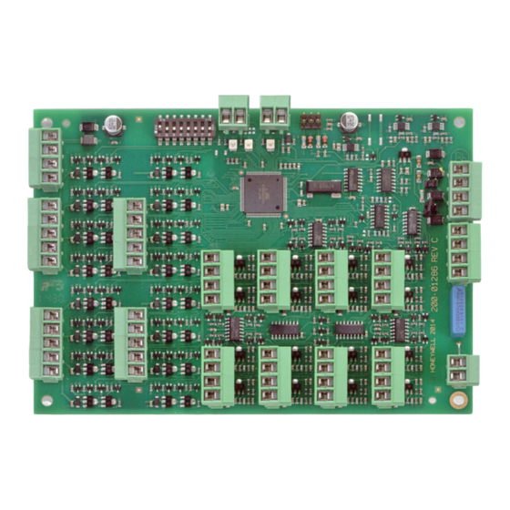
Page 4: Platinenaufbau - Übersicht
16 Ausgänge 16 Eingänge Die Anschlussklemmen sind steckbar. Alternativ dazu sind Lötsteckleisten möglich. Funktionsbeschreibung Die IB2 16 I/O-Erweiterung wird als BUS-2 Teilnehmer an der MB-Secure Zentrale angeschlossen. 16 Ausgänge, Auf der Platine befinden sich welche über die Zentralenprogrammierung programmiert werden können als:... -
Page 5: Montage
Montage-Anschluss-Anleitung IB2 16 I/O Erweiterung Montage Richtlinien Die Montage erfolgt auf dem Metall-Gehäuseboden der Zentrale oder in einem abgesetzten Metallgehäuse. Die Platinengröße entspricht den bisher bekannten I-BUS Modulen. Beachten Sie das Kap. "Erdung und Abschirmung" in der Installationsanleitung der Zentrale MB- Secure. -
Page 6: Montage In Ein Separates Gehäuse
Montage-Anschluss-Anleitung IB2 16 I/O Erweiterung Montage in ein separates Gehäuse Wenn Sie das 16 I/O Modul in ein separates Metallgehäuse einbauen, verwenden Sie dazu ein geeignetes Gehäuse aus unserem Katalog. Bei Anlagen gemäß EN ist nur ein Gehäuse für MB-Secure Zentralen zulässig! (ZG20, ZG2, ZG3.1 oder ZG4). -
Page 7: Installationsrichtlinien
Montage-Anschluss-Anleitung IB2 16 I/O Erweiterung Installationsrichtlinien BUS-Anschlussleitung Die BUS-Anschlussleitung muss als eine abgeschirmte, paarweise verseilte Leitung ausgeführt sein. Hierbei muss die Adernführung nach dem unten angegebenen Schema erfolgen. Die entsprechenden Leiterquerschnitte sind in der Installationsanleitung der Einbruchmelderzentrale (Kapitel Leitungen) zu entnehmen. -
Page 8: Programmierung
Änderungen der DIP-Schalterstellungen werden nur nach Reset übernommen. Ausnahme DIP-Schalter S8: dieser wird im Betrieb sofort übernommen. Bus-Abschlusswiderstand 6.2.1 Abschlusswiderstand an IB2-Schnittstelle Mit den Jumpern JP1 und JP2 wird der Abschlusswiderstand der IB2-Schnittstelle aktiviert oder deaktiviert. Grundsätzlich gilt: Die Bus-Leitung muss an beiden Enden... -
Page 9: Bus Betriebsmodus
Montage-Anschluss-Anleitung IB2 16 I/O Erweiterung BUS Betriebsmodus IB2 Betrieb Stellung ON (keine Adresse erforderlich) BUS-2 Betrieb Stellung OFF (Adresse s. u.) 1 2 3 4 5 BUS Betriebsmodus BUS-2 Adresse alle Schalter in BUS-2 Adresse Stellung "OFF" 1 2 3 4 5 6... -
Page 10: Anschlusspläne
Montage-Anschluss-Anleitung IB2 16 I/O Erweiterung Anschlusspläne Übersicht Sabotage: U_EXT: 5 - 30 V DC Spannungseingang für Abreißkontakt (Wall) Sabotagekontakt (Tamper) Output high-aktiv 1 2 3 4 5 U-EXT DIP-Schalter LED 1 U-EXT IB2- / BUS-2 von der Zentrale IB2- / BUS-2 zum nächsten... -
Page 11: Ausgänge
Montage-Anschluss-Anleitung IB2 16 I/O Erweiterung Melder, z. B. 8.2.2 Eingang mit Double Balanced Auswertung Bewegungsmelder Zustand Sollwert Bereich Störung Kurzschluss £ IN1 – 16 bis 1,5 k Alarm 1,5 k bis 3,2 k Alarm Störung 3,2 k bis 4,5 k Alarm + Störung... -
Page 12: Anschlussprotokoll
Montage-Anschluss-Anleitung IB2 16 I/O Erweiterung Anschlussprotokoll Eingänge Eingang 1 Meldergruppe Double Balanced IN 1 Eingang als Ausgang „low-Aktiv“ Eingang 2 Meldergruppe Double Balanced IN 2 Eingang als Ausgang „low-Aktiv“ Eingang 3 Meldergruppe Double Balanced IN 3 Eingang als Ausgang „low-Aktiv“... -
Page 13: Ausgänge
Montage-Anschluss-Anleitung IB2 16 I/O Erweiterung Ausgänge Ausgang 1 Ausgang „low-Aktiv“ OUT 1 Ausgang „high-Aktiv“ Ausgang 2 Ausgang „low-Aktiv“ OUT 2 Ausgang „high-Aktiv“ Ausgang 3 Ausgang „low-Aktiv“ OUT 3 Ausgang „high-Aktiv“ Ausgang 4 Ausgang „low-Aktiv“ OUT 4 Ausgang „high-Aktiv“ Ausgang 5 Ausgang „low-Aktiv“... -
Page 14: Technische Daten
Montage-Anschluss-Anleitung IB2 16 I/O Erweiterung Technische Daten Betriebsnennspannung 12 V DC Betriebsspannungsbereich 9,5 V DC bis 15 V DC Stromaufnahme bei UB = 12 V DC: - Ruhestrom Betriebsart BUS-2 20 mA - Ruhestrom Betriebsart IB2 55 mA - pro abgeschlossenem Eingang (12k1) - Page 15 Mounting and Connection Instructions IB2 16 I/O Expander Item no. 013940 P00185-10-002-03 Subject to change approval G115068 without notice 2016-01-19...
- Page 16 Mounting and Connection Instructions IB2 16 I/O Expander Contents Page 1. Application ............. . . 17 2.
-
Page 17: Application
They can also be used for the activation of relays, e.g. relay module Item No. 013941. Performance features: • Bus connection to the control panel can be switched to BUS-2 or IB2. • Installation in the control panel housing or remotely with a cable length of up to 1000 m •... -
Page 18: Circuit Board Design - Overview
Mounting and Connection Instructions IB2 16 I/O Expander Circuit board design – overview U_EXT 5 - 30 V DC Tear-off protection Tamper switch Voltage for (Wall) (Tamper) high-active output 1 2 3 4 5 DIP switch LED 1 2 IB2- / BUS-2... -
Page 19: Mounting
Mounting and Connection Instructions IB2 16 I/O Expander Mounting Guidelines Mounting on the metal housing base of the control panel or in a separate metal housing. The circuit board size corresponds with the existing I-BUS modules. Please refer to Chapter “Grounding and Shielding” in the Instructions for the Installer of the MB- Secure control panel. -
Page 20: Mounting In A Separate Housing
Mounting and Connection Instructions IB2 16 I/O Expander Mounting in a separate housing When installing the 16 I/O module in a separate housing, use a suitable housing from our catalog. As per EN, only a MB-Secure housing is permitted. (ZG20, ZG2, ZG3.1 or ZG4). -
Page 21: Installation Guidelines
Mounting and Connection Instructions IB2 16 I/O Expander Installation guidelines BUS connecting cable The BUS connecting cable must be a shielded, twisted pair line. Wires must correspond with the diagram below. The corresponding line cross-sections can be found in the Installation Instructions of the intruder alarm control panel (See chapter “Lines”). -
Page 22: Programming
Mounting and Connection Instructions IB2 16 I/O Expander Programming Position of jumpers and DIP switch 1 2 3 4 5 DIP switch U-EXT LED 1 2 U-EXT Changes to the DIP switch positions are only accepted after a reset. With the exception of the DIP switch S8 which is immediately accepted when in operation. -
Page 23: Bus Operating Mode
Mounting and Connection Instructions IB2 16 I/O Expander Bus operating mode IB2 operating mode in position ON (no address required) BUS-2 operating mode in position OFF 1 2 3 4 5 Bus operating mode All switche s set BUS-2 user address at "OFF"... -
Page 24: Connection Diagram
Mounting and Connection Instructions IB2 16 I/O Expander Connection diagram PCB overview Tamper connection: U_EXT: 5 - 30 V DC Tear-off protection (Wall) Tamper switch (Tamper) Voltage for high-active output 1 2 3 4 5 U-EXT DIP switch LED 1... -
Page 25: Outputs
Mounting and Connection Instructions IB2 16 I/O Expander Detector, e.g. 8.2.2 Input with double balanced evaluation Motion detector Status Nominal value Range Short circuit £ Fault good to 1.5 k IN1 – 16 Alarm 1.5 k to 3.2 k Alarm Fault 3.2 k... -
Page 26: Connection Protocol
Mounting and Connection Instructions IB2 16 I/O Expander Connection Protocol Inputs Input 1 Detector Group Double Balanced IN 1 Input as „low-active“ output Input 2 Detector Group Double Balanced IN 2 Input as „low-active“ output Input 3 Detector Group Double Balanced IN 3 Input as „low-active“... -
Page 27: Outputs
Mounting and Connection Instructions IB2 16 I/O Expander Outputs Output 1 “low-active” output OUT 1 “high-active” output Output 2 “low-active” output OUT 2 “high-active” output Output 3 “low-active” output OUT 3 “high-active” output Output 4 “low-active” output OUT 4 “high-active” output Output 5 “low-active”... -
Page 28: Technical Data
Mounting and Connection Instructions IB2 16 I/O Expander Technical Data Rated operating voltage 12 V DC Operating voltage range 9.5 V DC to 15 V DC Current consumption at UB = 12 V DC: - No-load current operating mode BUS-2...
Need help?
Do you have a question about the IB2 and is the answer not in the manual?
Questions and answers