Table of Contents
Advertisement
Quick Links
INSTALLATION INSTRUCTIONS FOR DCP-FRCME-EEPROM FAST RESPOND CONTACT
MONITORING MODULE
The information contained in this installation instruction is a quick reference guide. For detailed system
information refer to the panel manufacturers installation manual. This instruction is generic and will not address
specific programming procedures.
GENERAL DESCRIPTION:
This instruction applies to the DCP EEPROM Fast Response Contact
Monitoring Module (FRCME) which is to be connected to a DCP
Signaling Line Circuit (SLC). Typical applications are manual pull
stations, water flow devices or any dry contact alarm device, either
N/O or N/C contacts can be monitored.
MOUNTING REQUIREMENTS:
The DCP FRCME Module has two mounting options. The
FRCME-P is shown in Fig. 2, the FRCME-4 is shown in Fig. 3. All
the modules will follow Fig. 2A & 3A for wiring connections.
WIRING:
NOTE: All wiring must conform to local codes, ordinances and
regulations.
1) Install module wiring in accordance with the job drawings and
appropriate wiring diagram (see Fig. 2A & 3A).
2) Secure the module to a U.L. listed electrical box (supplied by
installer) as shown in Fig. 2, 3.
3) The address must be set on the FRCME-4 before the cover plate is
attached (see Fig. 1).
CAUTION !!!
TO ENSURE PROPER
OPERATION CONNECT THIS
MODULE TO A COMPATIBLE
FIRE CONTROL PANEL ONLY.
REFER TO PANEL
INSTRUCTIONS FOR PROPER
CONNECTION AND
COMPATIBILITY.
Note:
R adio F requency I nterference and E lectro- M agnetic I nterference are sources
of noise that can adversely affect the fire alarm systems installation.
When installing fire alarm system devices, avoid placing devices or
wiring close to potential noise sources such as:
•
Transmitters or antennas;
•
Ballast lighting;
•
Electrical motors;
•
Large power transformers;
•
Large machines.
Avoid running SLC circuit in the same conduit as power lines. Utilize twisted
pair and shielded wire in environments where excessive noise is expected.
Absolute Maximum
Applied Voltage
Supply Voltage Nominal
Average Current
Consumption
Maximum Current
Consumption
End of Line Device for Input
Operating Temperature Range
Storage Temperature
Max relative humidity
Dimensions
Weight
Environment
Visual Indicator
(FRCME-4 only)
(status LED)
HOCHIKI AMERICA CORPORATION
7051 VILLAGE DRIVE, SUITE 100
BUENA PARK, CA 90621-2268
CAUTION !!!
If this module will be installed in an
existing operational system, inform the
operator and local authority that the system
will be temporarily out of service.
Disconnect power to the control panel
before installing the module.
S, SC: 41 VDC
S, SC: 33 VDC
550 A (Typical)
Surge current: 30mA (in 5 ms.)
Alarm and response: 30mA (in 20 ms.)
No Alarm and no response: 660 A
U.L.listed EOL device Part No. 0400-01046 (10K OHM 1/4W)
0°C (32°F) ~ 49°C (120°F)
-30°C (-22°F) ~ 70°C (158°F)
Up to 90% RH non-condensing
4.2"W X 4.7"H X 1.4"D
Approximately 3.0 ounces
Indoor use only
bi-color LED - Green and Red
Color and mode - selected and programmed by Control Panel's software
(pulsing, steady, etc.)
FRCME-4 MODULE ADDRESS PROGRAMMING
CONNECTION AND INDICATOR
PROGRAMMING PLUG
(NON-POLARIZED)
FIGURE 1.
FRCME-4 PROGRAMMING CONNECTIONS
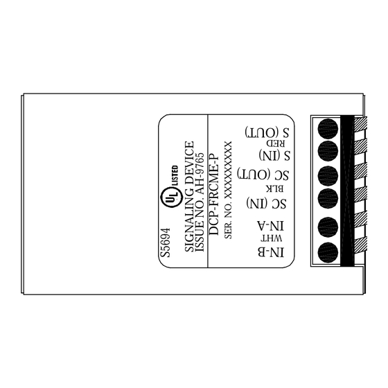
To program the FRCME-P,
connect the red alligator clip to
the S(In) wire and the black
alligator clip to the SC(In) wire
(see figure 1A). For proper
address setting, polarity must
be observed.
FIGURE 1A.
FRCME-P PROGRAMMING CONNECTIONS
STATUS LED
TO PROGRAMMER
TO PROGRAMMER
HA-06-102
DWG. #
(PG 1 OF 3 12/03)
PART# 1700-09959
Advertisement
Table of Contents

Subscribe to Our Youtube Channel
Related Manuals for Hochiki DCP-FRCME-EEPROM


Summary of Contents for Hochiki DCP-FRCME-EEPROM
- Page 1 INSTALLATION INSTRUCTIONS FOR DCP-FRCME-EEPROM FAST RESPOND CONTACT MONITORING MODULE The information contained in this installation instruction is a quick reference guide. For detailed system information refer to the panel manufacturers installation manual. This instruction is generic and will not address specific programming procedures.
- Page 2 PLACE THE FRCME-P MODULE INTO ANY BACK BOX (SINGLE GANG SHOWN) TABLE 1: WIRING LIMITATIONS Maximum Distance Between FIGURE 2 Module and EOL Device EXPLODED VIEW OF MOUNTING OPTION USING FRCME-P 14 AWG 1500 Ft. 16 AWG 900 Ft. 18 AWG 550 Ft.
- Page 3 One Year Limited Warranty Hochiki America (HA) warrants its digital communication modules to be in conformance with it's own plans and specifications and to be free from defects in materials and workmanship under normal use and service for a period of one (1) year from date of delivery.
Need help?
Do you have a question about the DCP-FRCME-EEPROM and is the answer not in the manual?
Questions and answers