Table of Contents
Advertisement
Advertisement
Table of Contents

Related Manuals for Toshiba BA410T Series


Summary of Contents for Toshiba BA410T Series
- Page 1 TOSHIBA Barcode Printer BA410T SERIES Owner's Manual...
- Page 2 (EU) 2015/863 for this product and the electric accessories. CE marking is the responsibility of TOSHIBA TEC GERMANY IMAGING SYSTEMS GmbH, Carl-Schurz- Str. 7, 41460 Neuss, Germany, phone +49-(0)-2131-1245-0. For a copy of the related CE Declaration of Conformity, please contact your dealer or TOSHIBA TEC. VORSICHT: •...
- Page 3 This symbol is applicable for EU member states only” Battery users must not dispose of batteries as unsorted general waste, but treat properly.” La siguiente información es solo para Argentina: El uso de este símbolo indica que este producto no puede ser tratado como residuos domésticos. Asegúrese que este producto se deseche correctamente, Usted ayudara a evitar posibles consecuencias negativas para el medio ambiente y la salud humana, que podrían derivarse de la incorrecta manipulación de este producto.
- Page 4 TOSHIBA TEC sales agent. Do not disassemble, modify, or repair the product as doing so may cause injury. Modification is also against the Laws and Regulations for Radio Equipment. Please ask your TOSHIBA TEC sales agent for repair.
-
Page 5: Table Of Contents
CAUTION! 1. This manual may not be copied in whole or in part without prior written permission of TOSHIBA TEC. 2. The contents of this manual may be changed without notification. -
Page 6: Product Overview
ENGLISH VERSION 1.1 Introduction 1. PRODUCT OVERVIEW Thank you for choosing the TOSHIBA BA410T series barcode printer. 1.1 Introduction This Owner’s Manual contains from general set-up through to how to confirm the printer operation using a test print, and should be read carefully to help gain maximum performance and life from your printer. -
Page 7: Accessories
1. PRODUCT OVERVIEW ENGLISH VERSION 1.3 Accessories When unpacking the printer, please make sure all the following Accessories accessories are supplied with the printer. Start-up CD-ROM (1 pc.) NOTE: As a power cord is not supplied <Contents> • Bar code print application (Bartender ultra-lite) with this printer, please purchase •... -
Page 8: Appearance
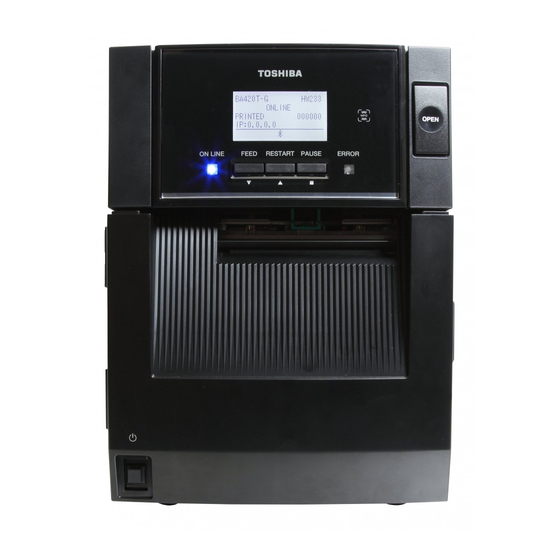
1. PRODUCT OVERVIEW ENGLISH VERSION 1.4 Appearance The names of the parts or units introduced in this section are used in the 1.4 Appearance following chapters. 1.4.1 Dimensions Dimensions in mm (inches) 1.4.2 Front View Top Cover Supply Window Ribbon Cover LCD Message Top Cover Display... -
Page 9: Operation Panel
1. PRODUCT OVERVIEW ENGLISH VERSION 1.4 Appearance 1.4.4 Operation Panel LCD Message Display ERROR LED ON LINE LED (Orange) (Blue) [PAUSE] key [FEED] key [RESTART] key Please see Section 4.1 for further information about the Operation Panel. 1.4.5 Interior Ribbon Cover Caution Labels: WARNING! Ribbon Stopper... -
Page 10: Options
1. PRODUCT OVERVIEW ENGLISH VERSION 1.5 Options Options Option Name Type Usage Cutter module BA204-QM-S A guillotine cutter which cuts the media. This module is slim and compact enough to fit inside the Front Cover. Strip module BA904-H-QM-S This module peels off a printed label from the backing paper at the media outlet. -
Page 11: Printer Setup
2. PRINTER SETUP ENGLISH VERSION 2. PRINTER SETUP 2. PRINTER SETUP This section outlines the procedures to setup your printer prior to its operation. The section includes precautions, loading media and ribbon, connecting cables, setting the operating environment of the printer, and performing an online print test. -
Page 12: Installation
2. PRINTER SETUP ENGLISH VERSION 2.1 Installation To insure the best operating environment, and to assure the safety of the 2.1 Installation operator and the equipment, please observe the following precautions. • Operate the printer on a stable, level surface in a location free from excessive humidity, high temperature, dust, vibration and direct sunlight. -
Page 13: Loading The Media
2. PRINTER SETUP ENGLISH VERSION 2.3 Loading the Media The following procedure shows the steps to properly load the media into the printer so that it feeds straight and true through the printer. 2.3 Loading the Media Use the same procedure when replacing the media, also. The printer prints both labels and tags. - Page 14 2. PRINTER SETUP ENGLISH VERSION 2.3 Loading the Media 5. Put the Media Holder (Left) onto the Media Shaft. Push the Media 2.3 Loading the Media Holder (Left) and the Media Holder (Right) against the media until the (Cont.) media is held firmly in place. This will automatically center the media.
- Page 15 2. PRINTER SETUP ENGLISH VERSION 2.3 Loading the Media Pull the media out of the front of the printer, and adjust the Media 2.3 Loading the Media Guides to the media width. This will automatically center the media. (Cont.) Media Guide CAUTION! 10.
- Page 16 2. PRINTER SETUP ENGLISH VERSION 2.3 Loading the Media 11. After loading the media, it may be necessary to set the position of 2.3 Loading the Media the Media Sensor used to detect the print start position for label or (Cont.) tag printing.
- Page 17 2. PRINTER SETUP ENGLISH VERSION 2.3 Loading the Media Setting the Black Mark Sensor position 2.3 Loading the Media (Cont.) When using media with black marks, the Black Mark Sensor is used to detect a print start position. (1) Push the Upper Sensor Lever inside and open the Upper Sensor NOTES: Ass’y.
- Page 18 2. PRINTER SETUP ENGLISH VERSION 2.3 Loading the Media 12. There are three issue modes available on this printer. How to set the 2.3 Loading the Media media for each mode is provided below. (Cont.) Batch mode In the batch mode, the media is continuously printed and fed until the number of labels/tags specified in the issue command have been printed.
- Page 19 2. PRINTER SETUP ENGLISH VERSION 2.3 Loading the Media (2) Press down the Release Bar to open the Strip Module. 2.3 Loading the Media Release Bar (Cont.) Strip Module (3) Remove enough labels from the leading edge of the media to leave 300mm of backing paper free.
- Page 20 2. PRINTER SETUP ENGLISH VERSION 2.3 Loading the Media 2.3 Loading the Media Cut mode (Option) (Cont.) When the optional Cutter Module is fitted, the media is automatically cut. WARNING! Insert the leading edge of the media into the Media Outlet of the Cutter Module.
-
Page 21: Loading The Ribbon
2. PRINTER SETUP ENGLISH VERSION 2.4 Loading the Ribbon There are two types of media available for printing on: these are thermal 2.4 Loading the Ribbon transfer media (normal media) and direct thermal media (with a chemically treated surface). DO NOT LOAD a ribbon when using a WARNING! direct thermal media. - Page 22 2. PRINTER SETUP ENGLISH VERSION 2.4 Loading the Ribbon 3. Open the Top Cover. 2.4 Loading the Ribbon (Cont.) Top Cover Top Cover Stopper 4. Open the Ribbon Cover. Ribbon Cover 5. Fit the ribbon take-up core into the Ribbon Holder (Take-up side), aligning the notch of the ribbon core with the protrusion of the Ribbon Stopper.
- Page 23 2. PRINTER SETUP ENGLISH VERSION 2.4 Loading the Ribbon Close the Ribbon Cover until it clicks. 2.4 Loading the Ribbon (Cont.) WARNING! Ribbon Cover Be sure to close the Ribbon Cover before closing the Top Cover. It is dangerous to close the Top Cover with the Ribbon Cover opened, as the Ribbon Top Cover...
-
Page 24: Connecting The Printer To Your Host Computer
2. PRINTER SETUP ENGLISH VERSION 2.5 Connecting the Printer to Your Host Computer The following paragraphs outline how to connect your host computer to 2.5 Connecting the the printer, and will also show how to make cable connections to other Printer to Your Host devices. -
Page 25: Turning The Printer On
2. PRINTER SETUP ENGLISH VERSION 2.6 Turning the Printer ON When the printer is connected to your host computer it is good practice to 2.6 Turning the Printer turn the printer ON before turning on your host computer and turn OFF your host computer before turning off the printer. -
Page 26: Maintenance
Print Head. Element 3. Be sure to use a Print Head Cleaner. Failure to do this may shorten the Print Head life. NOTE: A Print Head Cleaner (P/No. 24089500013) is available from your authorised TOSHIBA TEC service representative. -
Page 27: Covers And Panels
3. MAINTENANCE ENGLISH VERSION 3.1 Cleaning 5. Wipe the Platen and Dumper Roller with a soft cloth slightly 3.1.1 Print Head/Platen/ moistened with absolute ethyl alcohol. Remove dust or foreign Sensors (Cont.) substances from the internal part of the printer. 6. -
Page 28: Optional Cutter Module
3. MAINTENANCE ENGLISH VERSION 3.1 Cleaning 3.1.3 Optional Cutter Module 1. Open the Front Cover. (*Note) 2. Loosen the Set Screw of the Cutter Module to open it. 3. Remove jammed media, if any. NOTE: To open and close the Front Cover, first open the Top Cover. -
Page 29: Optional Strip Module
3. MAINTENANCE ENGLISH VERSION 3.1 Cleaning 3.1.4 Optional Strip Module 1. Open the Front Cover holding its right side. (*Note) NOTE: To open and close the Front Cover, first open the Top Front Cover Cover. If it is difficult to open the Front Cover, hold the cover handle at the bottom. -
Page 30: Troubleshooting
WARNING! If a problem cannot be solved by taking the actions described in this chapter, do not attempt to repair the printer. Turn off and unplug the printer, then contact an authorized TOSHIBA TEC service representative 4.1 Error Messages NOTES: If an error is not cleared by pressing the key, turn the printer off and then on. - Page 31 RIBBON ERROR of the ribbon. Replace the ribbon, if necessary. If the problem is not solved, turn off the printer, and call a TOSHIBA TEC authorised service representative. 2. The ribbon has run out. 2. Load a new ribbon. Then press the [RESTART] key.
-
Page 32: Possible Problems
Other error messages have occurred. does not solve the problem, turn off the printer again, and call a TOSHIBA TEC authorised service representative. 4.2 Possible Problems This section describes problems that may occur when using the printer, and their causes and solutions. -
Page 33: Removing Jammed Media
Ass’y. 4. Remove the ribbon and media from the printer. NOTE: If you get frequent jams in the cutter, contact a TOSHIBA TEC authorised service Upper Sensor Ass’y representative. 5. Remove the jammed media from the printer. DO NOT USE any sharp implements or tools as these could damage the printer. -
Page 34: Printer Specifications
5. PRINTER SPECIFICATIONS ENGLISH VERSION 5. PRINTER SPECIFICATIONS 5. PRINTER SPECIFICATIONS This section describes the printer specifications. Model BA410T-GS12-QM-S BA410T-TS12-QM-S Item Dimension (W × D × H) 238 mm × 401.7 mm × 331.5 mm (9.4” × 15.8” × 13.1”) Weight 33.1 lb (15 kg) (Media and ribbon are not included.) Operating... - Page 35 5. PRINTER SPECIFICATIONS ENGLISH VERSION 5. PRINTER SPECIFICATIONS Model BA410T-GS12-QM BA410T-TS12-QM Item Available bar code types JAN8, JAN13, EAN8, EAN8+2 digits, EAN8+5 digits, EAN13, EAN13+2 digits, EAN13+5 digits, UPC-E, UPC-E+2 digits, UPC-E+5 digits, UPC-A, UPC-A+2 digits, UPC-A+5 digits, MSI, ITF, NW-7, CODE39, CODE93, CODE128, EAN128, Industrial 2 to 5, Customer Bar Code, POSTNET, KIX CODE, RM4SCC (ROYAL MAIL 4STATE CUSTOMER CODE), GS1 DataBar, MATRIX 2 of 5 for NEC,...
-
Page 36: Appendix1 Interface
6. APPENDIX 1 INTERFACE ENGLISH VERSION 6. APPENDIX 1 INTERFACE 6. APPENDIX 1 INTERFACE NOTE: To prevent radiation and reception of electrical noise, the interface cables must meet the following requirements: • In case of a parallel interface cable or serial interface cable, fully shielded and fitted with metal or metallised connector housings. - Page 37 6. APPENDIX 1 INTERFACE ENGLISH VERSION 6. APPENDIX 1 INTERFACE Bluetooth (Standard) Module Name: MBH7BTZ42 Bluetooth version: V2.1 + EDR Frequency: 2.4000 to 2.4835 GHz Maximum Transmit: Class 2 Power: +4dBm (Except antenna gain) Receive Sensitivity: -87 dBm Data Rates: 1Mbps (Basic Rate)/2Mbps (EDR 2Mbps)/3Mbps (EDR 3Mbps)"...
- Page 38 6. APPENDIX 1 INTERFACE ENGLISH VERSION 6. APPENDIX 1 INTERFACE Optional Parallel Interface BA700-CEN-QM-S Mode: Conforming to IEEE1284 Compatible mode (SPP mode), Nibble mode Data input method: 8 bit parallel Control signal: SPP Mode Nibble Mode nStrobe HostClk nAck PtrClk Busy PtrBusy...
- Page 39 6. APPENDIX 1 INTERFACE ENGLISH VERSION 6. APPENDIX 1 INTERFACE TWISTED PAIR GND(PIN9) TWISTED PAIR GND(PIN9) TWISTED PAIR GND(PIN10) TWISTED PAIR GND(PIN10) TWISTED PAIR GND(PIN11) TWISTED PAIR GND(PIN11) TWISTED PAIR GND(PIN31) TWISTED PAIR GND(PIN31) nInit nInit nFault NDataAvail nSelectIn IEEE1284Active IEEE1284-B Connector ...
- Page 40 6. APPENDIX 1 INTERFACE ENGLISH VERSION 6. APPENDIX 1 INTERFACE Optional EX I/O Module BA700-IO-QM-S Input Signal IN0 to IN5 Output Signal OUT0 to OUT6 Connector FCN-781P024-G/P or equivalent (External Device Side) Connector FCN-685J0024 or equivalent (Printer Side) Signal Function Signal Function...
- Page 41 6. APPENDIX 1 INTERFACE ENGLISH VERSION 6. APPENDIX 1 INTERFACE Optional RFID Module BA704-RFID-U4-KR-S, BA704-RFID-U4-EU-S, BA704-RFID-U4- AU-S • (Option)BA704-RFID-U4-KR-S Module: TRW-USM-10 Frequency: KR settings: 920.9-923.3 MHz (UHF Korea) Output: 1 to 100 mW Available RFID tag: EPC C1 Gen2, ISO-18000-6C •...
- Page 42 When the transmissive sensor or reflective sensor is enabled, transmittance or reflectivity of a label or tag may vary at an RFID-tag embedded area depending on the pattern of the antenna or other factors. In such cases, a manual threshold setting is required. For details, please contact the nearest TOSHIBA TEC support representative.
- Page 43 As the location, where data is to be written, differs among RFID tag types, a check must be performed to make sure that the data is written on the target RFID tags. The BCP RFID Analyze Tool can be used for this purpose. For details, please contact the nearest TOSHIBA TEC support representative. (11) Defective RFID Media RFID media may include defective RFID tags at the time of shipment from the maker.
-
Page 44: Appendix2 Power Cord
7. APPENDIX 2 POWER CORD When purchasing the power cord: Since the power cord set is not enclosed in this unit, please purchase an approved one that meets the following standard from your authorized TOSHIBA TEC representative. Certification Certification Country... - Page 45 PRINTED IN INDONESIA © 2019 TOSHIBA TEC CORPORATION All Rights Reserved EO1-33122 1-11-1, Osaki, Shinagawa-ku, Tokyo 141-8562, JAPAN...
Need help?
Do you have a question about the BA410T Series and is the answer not in the manual?
Questions and answers