
Subscribe to Our Youtube Channel
Related Manuals for Diamatic BMG-780


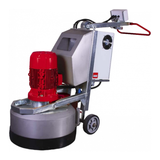
Summary of Contents for Diamatic BMG-780
- Page 1 MODEL BMG-780 GRINDER OPERATING MANUAL SECTION 2 SAFETY INSTRUCTIONS JANUARY 2008 Technical Data Safety Instructions MODEL BMG-780 General Planetary Grinder Transport Initial Operation Operation Maintenance Electrical Systems Fault Diagnosis Spare Parts Grinding & Polishing Grinding & Polishing...
-
Page 2: Technical Data
MODEL BMG-780 GRINDER OPERATING MANUAL SECTION 1 TECHNICAL DATA MARCH 2009 CONTENTS – SECTION 1 Rating Unit specifications Operative range and correct usage Stand-by power supply Machine type designation Grinding & Polishing... - Page 3 MODEL BMG-780 GRINDER OPERATING MANUAL SECTION 1 TECHNICAL DATA MARCH 2009 1.1 RATING Unit / Designation: Grinding Machine Machine Type: BMG-780 Manufacturer: 13201 North Santa Fe Utrechthaven 12 Oklahoma City, OK 73114 3433 PN Nieuwegein United States of America THE NETHERLANDS Local: 405-478-3440 T +31(0)30 –...
- Page 4 In these cases, the user takes responsibility for all risks. 1.4 STAND-BY SUPPLY (GENERATOR) If the BMG-780 is to be operated using power from a generator, the generator must be operated in accordance with the current U. S. National Electric Code guidelines or European VDE...
-
Page 5: Safety Instructions
MODEL BMG-780 GRINDER OPERATING MANUAL SECTION 2 SAFETY INSTRUCTIONS MARCH 2009 CONTENTS – SECTION 2 Warnings and symbols Organizational measures Personnel selection and qualification Safety precautions applicable to some operating sequences Special work within the scope of use of the equipment and maintenance... -
Page 6: General
MODEL BMG-780 GRINDER OPERATING MANUAL SECTION 2 SAFETY INSTRUCTIONS MARCH 2009 2.1 WARNINGS AND SYMBOLS The following denominations and symbols are used in the Operating Instructions to highlight areas of particular importance: Symbol of operational safety. In these Operating Instructions this symbol will be... -
Page 7: Organizational Measures
MODEL BMG-780 GRINDER OPERATING MANUAL SECTION 2 SAFETY INSTRUCTIONS MARCH 2009 Indicates where consultation with the manufacturer is required. Instructions relating to periodic checks. Reference to important instructions contained in the Operating Instructions. 2.2 ORGANIZATIONAL MEASURES These Operating Instructions are to be kept with the machine, and... - Page 8 MODEL BMG-780 GRINDER OPERATING MANUAL SECTION 2 SAFETY INSTRUCTIONS MARCH 2009 From time to time the working practices of the operators are to be checked by a supervisor, especially regarding awareness of safety and hazards. Operators must tie back long hair, and not wear loose clothing or jewelry including rings.
-
Page 9: Personnel Selection And Qualification
MODEL BMG-780 GRINDER OPERATING MANUAL SECTION 2 SAFETY INSTRUCTIONS MARCH 2009 2.3 PERSONNEL SELECTION AND QUALIFICATION Fundamental duties: Work on the machine may only be undertaken by trained personnel. Only trained personnel may be employed. Note the statutory minimum age. - Page 10 MODEL BMG-780 GRINDER OPERATING MANUAL SECTION 2 SAFETY INSTRUCTIONS MARCH 2009 Check the machine visually for any damage and defects at least once a day. In the event of operational malfunctions the machine must be shut down immediately and secured.
- Page 11 MODEL BMG-780 GRINDER OPERATING MANUAL SECTION 2 SAFETY INSTRUCTIONS MARCH 2009 2.5 SPECIAL WORK WITHIN THE SCOPE OF USE OF THE EQUIPMENT AND MAINTENANCE ACTIVITIES AS WELL AS REPAIRS DURING OPERATION Mechanical servicing work: Put the machine in the Safety off position as described in Section 2.6 before carrying out any service work on the machine.
- Page 12 MODEL BMG-780 GRINDER OPERATING MANUAL SECTION 2 SAFETY INSTRUCTIONS MARCH 2009 Observe the local waste disposal regulations; in uncertain situations ask the next higher authority. Do not use any aggressive cleaning materials. Only use lint-free cleaning cloths. Always verify that any bolted connections that were loosened during service and maintenance work are properly secure and tight.
- Page 13 MODEL BMG-780 GRINDER OPERATING MANUAL SECTION 2 SAFETY INSTRUCTIONS MARCH 2009 2.7 GENERAL SAFETY CONSIDERATIONS Any machine, if it is not used according to regulations, may be hazardous during operation, set-up and servicing. The machine owner is responsible for compliance with the safety regulations...
- Page 14 MODEL BMG-780 GRINDER OPERATING MANUAL SECTION 3 GENERAL MARCH 2009 CONTENTS – SECTION 3 Range of application Scope of supply Description of the machine Operating elements Electric components Upper part Lower part Tensioner upper belt Tensioner lower belt 3.10 Pulley 3.11 Center pulley...
-
Page 15: Range Of Application
SECTION 3 GENERAL MARCH 2009 3.1 RANGE OF APPLICATION Typical ranges of applications for the BMG-780 are for example: • To remove undulated concrete surfaces • To prepare the surface for coatings • To polish the surface • To remove coating defects •... - Page 16 Cover Upper Part Metal Dust Ring Lower Tensioner The BMG-780 has a working width of 780 mm and gives excellent performance due to its economic efficiency and easy handling. The machine is capable of leveling uneven and undulating floors. This process is suitable for an optimization of surfaces prior to blast...
-
Page 17: Operating Elements
3.4 OPERATING ELEMENTS Fig. 3.2 Before Switching on the BMG-780, the front part of the grinding machine must be lifted by pushing the handgrip (1) down to floor level till the machine is approximately 4 inches (10 cm) from the ground. The complete arm is adjustable by removing the pin (2). - Page 18 MODEL BMG-780 GRINDER OPERATING MANUAL SECTION 3 GENERAL MARCH 2009 3.5 ELECTRIC COMPONENTS The Switch box is equipped with all control elements and instruments to monitor the grinding machine. Fig. 3.3 Current Display This display shows the amp draw on the motor during operation. It will also show faults in the event of a safety not being in place and if any voltage/wiring problems occur.
- Page 19 MODEL BMG-780 GRINDER OPERATING MANUAL SECTION 3 GENERAL MARCH 2009 Emergency Stop This red mushroom-shaped switch when pressed will immediately cut off the power supply to the panel and motor and bring the machine to rest. To restart the machine the switch must be reset.
- Page 20 MODEL BMG-780 GRINDER OPERATING MANUAL SECTION 3 GENERAL MARCH 2009 3.6 UPPER PART The upper part of the BMG 780 is where the drive system for the machine is located. The rotational drive is powered through a speed reduction drive belt and pulley system, which also gives rotation to the grinder head and drive to the center pulley.
- Page 21 MODEL BMG-780 GRINDER OPERATING MANUAL SECTION 3 GENERAL MARCH 2009 3.7 LOWER PART The lower part of the BMG 780 is where the drive pulleys and the diamond tool holders are fitted. On the driving pulley, there is a coupling which is driven by the electric motor.
- Page 22 MODEL BMG-780 GRINDER OPERATING MANUAL SECTION 3 GENERAL MARCH 2009 3.8 LOWER PART The upper belt tensioner keeps the upper belt tight. By taking off the cover of the upper part, the tensioner can be accessed. Fig. 3.6 Axle Flat Head Socket Cap Screw Retaining ring ...
-
Page 23: Table Of Contents
MODEL BMG-780 GRINDER OPERATING MANUAL SECTION 3 GENERAL MARCH 2009 3.9 TENSIONER LOWER BELT The lower belt tensioner keeps the lower belt tight. By taking off one of the two inspection hole covers at the bottom of the lower plate the tensioner can be accessed. - Page 24 MODEL BMG-780 GRINDER OPERATING MANUAL SECTION 3 GENERAL MARCH 2009 3.10 PULLEY There are three pulleys in the machine. Under these pulleys the diamond discs are fixed. The pulley is driven by the driving pulley through a belt. The pulley is fixed on the lower housing with screws.
- Page 25 MODEL BMG-780 GRINDER OPERATING MANUAL SECTION 3 GENERAL MARCH 2009 3.11 CENTER PULLEY The center pulley will slow down the speed of the lower housing. The six head cap screws connect the pulley with the lower housing. Fig. 3.9 Sprocket...
- Page 26 MODEL BMG-780 GRINDER OPERATING MANUAL SECTION 3 GENERAL MARCH 2009 3.12 CONTRA PULLEY The contra pulley gives a reduction of speed to the lower housing. The belt pulley is driven by a belt from the motor pulley. Fig. 3.11 Axle Ring Bearing ...
- Page 27 MODEL BMG-780 GRINDER OPERATING MANUAL SECTION 3 GENERAL MARCH 2009 3.13 DRIVING PULLEY On the driving pulley shaft, there is a coupling which is driven by the electric motor. The driving pulley drives the three pulleys with a belt. The pulley is fixed on the lower housing with screws.
- Page 28 MODEL BMG-780 GRINDER OPERATING MANUAL SECTION 3 GENERAL MARCH 2009 3.14 DIAMOND TOOLING There are three types of tooling that can be put under the diamond tooling. The three types are: Diamond Segments Polycrystalline (PCD) Diamond Segments Polishing Resins Diamond Segments The diamond tools are designed for use on concrete floors.
- Page 29 MODEL BMG-780 GRINDER OPERATING MANUAL SECTION 3 GENERAL MARCH 2009 3.15 CORD REEL (OPTIONAL) 3.16 WATER TANK AND PIPING (OPTIONAL) 3.17 FRONT SUPPORT CASTER (OPTIONAL) Grinding & Polishing...
-
Page 30: Care And Maintenance
Only use genuine parts. Generally the grinding machine BMG-780 requires very little special attention regarding its maintenance. Verify that any wastes or fiber residues do not remain in the area of the grinding disc. - Page 31 MODEL BMG-780 GRINDER OPERATING MANUAL SECTION 3 GENERAL MARCH 2009 ________________________________________________________________ Notes ________________________________________________________________ Grinding & Polishing...
- Page 33 MODEL BMG-780 GRINDER OPERATING MANUAL SECTION 4 TRANSPORT MARCH 2009 CONTENTS – SECTION 4 Unit specifications Manual mode of moving the machine Transport with cranes or lifts Transport of the machine with vehicle Operation of the machine while grinding 4.1 UNIT SPECIFICATIONS...
- Page 34 MODEL BMG-780 GRINDER OPERATING MANUAL SECTION 4 TRANSPORT MARCH 2009 4.2 MANUAL MODE OF MOVING THE MACHINE To move the machine, press down the handgrips of the machine (see fig.4.1) until the front part rises off the ground and the machine is well balanced. It can now be pushed around on its wheels.
-
Page 35: Initial Operation
MODEL BMG-780 GRINDER OPERATING MANUAL SECTION 4 TRANSPORT MARCH 2009 4.3 TRANSPORT WITH CRANES OR LIFTS If the machine is to be transported by a crane or a fork lift, verify that the lifting strap(s) has sufficient capacity to support the weight of the machine. The gross weight is shown in Section 4.1 Unit specifications and also on the serial number... -
Page 36: Operation
MODEL BMG-780 GRINDER OPERATING MANUAL SECTION 5 INITIAL OPERATION MARCH 2009 CONTENTS – SECTION 5 Preparation for initial operation Initial operation Grinding & Polishing... -
Page 37: Maintenance
Use hose clamps at the connections. • Make sure the dust bin of the dust collector unit is empty. If problems with the BMG-780 arise during the assembly or start- up, call a qualified person for help. Work on electrical equipment may only be undertaken by qualified personnel . - Page 38 MODEL BMG-780 GRINDER OPERATING MANUAL SECTION 5 INITIAL OPERATION MARCH 2009 5.2 INITIAL OPERATION Fig. 5.1 Fig. 5.2 Switching on the grinding machine: • Make sure the motor is connected to the plug on the bottom of the panel with the supplied cord.
- Page 39 MODEL BMG-780 GRINDER OPERATING MANUAL SECTION 5 INITIAL OPERATION MARCH 2009 Switching off the grinding machine: • Push down on the handgrips (2). • Push the “STOP” button (4) on the operator control panel. • In case of emergency, push the “Emergency Stop” button (8).
- Page 40 MODEL BMG-780 GRINDER OPERATING MANUAL SECTION 6 OPERATION MARCH 2009 CONTENTS – SECTION 6 Operation Switching-off the machine Trouble shooting Safety shutdown Restarting after a fault Proceedings- before and after a stationary period Grinding & Polishing...
- Page 41 Regular inspection is necessary to prevent unplanned down time of your grinding machine. See Section 7.2 Maintenance. Pay attention to following aspects during operation of the BMG-780. Before beginning the grinding work, verify that all bolted connections are properly secured and tight.
- Page 42 MARCH 2009 The process described in Section 5.2 “Initial Operation” shall be followed during the normal start up of the BMG-780 for daily operation. If there are any doubts as to how to start up the machine, read Sections 5.1 and 5.2 of this operating manual.
- Page 43 MODEL BMG-780 GRINDER OPERATING MANUAL SECTION 6 OPERATION MARCH 2009 6.3 TROUBLE SHUTDOWN In case of emergency or operating trouble, such as vibrations or loud noises, switch the machine off immediately by pushing the Emergency Stop (E-Stop) button on the operator control panel (8) .
- Page 44 MODEL BMG-780 GRINDER OPERATING MANUAL SECTION 6 OPERATION MARCH 2009 6.6 PROCEEDINGS – BEFORE AND AFTER STATIONARY PERIOD Before a long stationary period: If the grinding machine will be out of action for a long period of time, protect the machine during storage per the following: •...
- Page 45 MODEL BMG-780 GRINDER OPERATING MANUAL SECTION 6 OPERATION MARCH 2009 ________________________________________________________________ Notes ________________________________________________________________ Grinding & Polishing...
- Page 46 MODEL BMG-780 GRINDER OPERATING MANUAL SECTION 7 MAINTENANCE MARCH 2009 CONTENTS – SECTION 7 Recommendations Maintenance and inspection list Repairing Grinding tool replacement / assembly Upper Part Lower part Pulley maintenance Other maintenance Recommended Spares for Stock 7.10 Influences on the Grinding Pattern...
- Page 47 MODEL BMG-780 GRINDER OPERATING MANUAL SECTION 7 MAINTENANCE MARCH 2009 7.1 RECOMMENDATIONS Prior to any repair work on the machine and its drives, secure the machine against unintentional activation. Put the machine in its safety off position. Section 2.6 Failures due to inadequate or incorrect maintenance may generate very high repair costs and potentially long periods of down time for the machine.
-
Page 48: Maintenance And Inspection List
MODEL BMG-780 GRINDER OPERATING MANUAL SECTION 7 MAINTENANCE MARCH 2009 7.2 MAINTENANCE AND INSPECTION LIST Operating hours/time period Inspection points, and maintenance instructions 12 hours after repairing Check all accessible screw connections for tightness. Daily and prior to starting work Verify all safety devices are working correctly. - Page 49 MODEL BMG-780 GRINDER OPERATING MANUAL SECTION 7 MAINTENANCE MARCH 2009 7.3 REPAIRING As previously mentioned in Section 5.1 Initial operation, we recommend conducting initial repair work on the machine with the support of personnel, by taking this advice, maintenance personnel get the opportunity to be trained by an expert on the machine.
- Page 50 MODEL BMG-780 GRINDER OPERATING MANUAL SECTION 7 MAINTENANCE MARCH 2009 7.4 GRINDING DISC REPLACEMENT/ASSEMBLY Prior to any repair work being carried out on the machine or its drives, secure the machine against unintentional activation. See Section 2.6. Fig. 7.1 Disassembly: Make sure that the power supply is disconnect from the electrical inlet (1).
- Page 51 MODEL BMG-780 GRINDER OPERATING MANUAL SECTION 7 MAINTENANCE MARCH 2009 7.5 UPPER PART Prior to any repair work being carried out on the machine or its drives, secure the machine against unintentional activation. See Section 2.6. Fig. 7.2 Disassembly: • Unscrew the bolts (1) on the topside, to enable the protection cover (2) to be removed.
- Page 52 MODEL BMG-780 GRINDER OPERATING MANUAL SECTION 7 MAINTENANCE MARCH 2009 7.6 LOWER PART Prior to any repair work being carried out on the machine or its drives, secure the machine against unintentional activation. See Section 2.6. Fig. 7.3 Disassembly: • Disassemble the diamond tool holders (1) and take off the v-seal (2).
- Page 53 MODEL BMG-780 GRINDER 7.7 PULLEY OPERATING MANUAL SECTION 7 MAINTENANCE MARCH 2009 Prior to any repair work being carried out on the machine or its drives, secure the machine against unintentional activation. See Section 2.6. Fig. 7.4 Disassembly: • Take off the retaining ring (1).
- Page 54 MODEL BMG-780 GRINDER OPERATING MANUAL SECTION 7 MAINTENANCE MARCH 2009 7.8 OTHER MAINTENANCE Check the dust seals for wear and replace them at the time when they no longer provide a good seal against dust emissions from the machine. This will ensure that there is no damage caused to the surrounding workspace and consequently saves additional cleanup charges from the job client.
- Page 55 MODEL BMG-780 GRINDER OPERATING MANUAL SECTION 7 MAINTENANCE MARCH 2009 7.9 RECOMMENDED SPARES FOR STOCK It is highly recommended, that having the following spare parts on stock will avoid unplanned downtime and/or long equipment downtime that may result from waiting for spare parts to ship.
- Page 56 MODEL BMG-780 GRINDER OPERATING MANUAL SECTION 8 MAINTENANCE MARCH 2009 CONTENTS – SECTION 8 Directions for electrical engineering Electrical Schematic - 230V / 50 and 60 HZ Control Panel Layout and Device Settings - 230V / 50 and 60 HZ Electrical Schematic –...
-
Page 57: Directions For Electrical Engineering
MODEL BMG-780 GRINDER OPERATING MANUAL SECTION 8 MAINTENANCE MARCH 2009 8.1 DIRECTIONS FOR ELECTRICAL ENGINEERING Work on electrical equipment or operating materials may only be performed by a skilled electrician or by trained persons under the guidance and supervision of a skilled electrician as well as in accordance with the electrical engineering regulations. - Page 58 MODEL BMG-780 GRINDER OPERATING MANUAL SECTION 8 MAINTENANCE MARCH 2009 8.2 ELECTRICAL SCHEMATICS - 23OV / 50 AND 60 HZ Grinding & Polishing...
- Page 59 MODEL BMG-780 GRINDER OPERATING MANUAL SECTION 8 MAINTENANCE MARCH 2009 8.3 CONTROL PANEL LAYOUT FOR 23OV / 50 AND 60 HZ Grinding & Polishing...
- Page 60 MODEL BMG-780 GRINDER OPERATING MANUAL SECTION 8 MAINTENANCE MARCH 2009 ITEM NUMBER DESCRIPTION P002889 ENCLOSURE W/ BACK PANEL P004971 VARIABLE FREQUENCY DRIVE (VFD) P004973 VFD, REMOTE KEYPAD P004786 SWITCH, DOUBLE PUSHBUTTON P004859 SWITCH, MOUNTING COLLAR P004861 SWITCH, CONTACT BLOCK, 1 - NO...
- Page 61 MODEL BMG-780 GRINDER OPERATING MANUAL SECTION 8 MAINTENANCE MARCH 2009 8.4 ELECTRICAL SCHEMATIC 460V / 50 AND 60 HZ Grinding & Polishing...
- Page 62 MODEL BMG-780 GRINDER OPERATING MANUAL SECTION 8 MAINTENANCE MARCH 2009 8.5 CONTROL PANEL LAYOUT FOR 460V / 50 AND 60 HZ Grinding & Polishing...
- Page 63 MODEL BMG-780 GRINDER OPERATING MANUAL SECTION 8 MAINTENANCE MARCH 2009 ITEM NUMBER DESCRIPTION P002889 ENCLOSURE W/ BACK PANEL P004972 VARIABLE FREQUENCY DRIVE P004973 REMOTE KEYPAD P004786 SWITCH, DOUBLE PUSHBUTTON P004859 SWITCH, MOUNTING COLLAR P004861 SWITCH, CONTACT BLOCK, 1 - NO...
-
Page 64: Fault Diagnosis
MODEL BMG-780 GRINDER OPERATING MANUAL SECTION 9 FAULT DIAGNOSIS MARCH 2009 CONTENTS – SECTION 9 Troubleshooting - grinding machine Troubleshooting - electrical system Grinding & Polishing... - Page 65 MODEL BMG-780 GRINDER OPERATING MANUAL SECTION 9 FAULT DIAGNOSIS MARCH 2009 9.1 TROUBLESHOOTING – GRINDING MACHINE Prior to any repair work on the machine or its drives, the machine must be secured against unintentional activation. Put the machine in its Safety off position. See section 2.6.
- Page 66 MODEL BMG-780 GRINDER OPERATING MANUAL SECTION 9 FAULT DIAGNOSIS MARCH 2009 9.2 TROUBLESHOOTING – ELECTRICAL SYSTEM Work on electrical equipment or operating materials may only be performed by a skilled electrician or by trained persons under the guidance and supervision of a skilled electrician as well as in accordance with the electrical engineering regulations.
- Page 67 MODEL BMG-780 GRINDER OPERATING MANUAL SECTION 9 FAULT DIAGNOSIS MARCH 2009 ________________________________________________________________ Notes ________________________________________________________________ Grinding & Polishing...
-
Page 68: Spare Parts
MODEL BMG-780 GRINDER OPERATING MANUAL SECTION 10 SPARE PARTS MARCH 2009 CONTENTS – SECTION 10 10.1 Spares Parts - BMG-780 Grinding & Polishing... - Page 69 MODEL BMG-780 GRINDER OPERATING MANUAL SECTION 10 SPARE PARTS MARCH 2009 10.1 SPARE PARTS – BMG-780 Frame Grinding & Polishing...
-
Page 70: Retaining Ring
MODEL BMG-780 GRINDER OPERATING MANUAL SECTION 10 SPARE PARTS MARCH 2009 Frame ITEM NO. PART NUMBER DESCRIPTION QTY. PG-10113 WELDMENT, 780 FRAME (US) PG-10177 ASSY, FRAME, FRONT CLIP EO1492 BUSHING BG11851 BG11854 BG11855 BUSHING BG11856 PG-10181 STEER, ADJUSTABLE PART PG-10140... - Page 71 MODEL BMG-780 GRINDER OPERATING MANUAL SECTION 10 SPARE PARTS MARCH 2009 Upper Part Grinding & Polishing...
- Page 72 MODEL BMG-780 GRINDER OPERATING MANUAL SECTION 10 SPARE PARTS MARCH 2009 Upper Part ITEM NO. PART NUMBER DESCRIPTION QTY. PA-10889 BELT GUARD PG-10044 UPPER TENSIONER 800781 M8 X 1.25 X 16 HEX HEAD CAP SCREW 800775 WASHER, 8MM, REGULAR 800776...
- Page 73 MODEL BMG-780 GRINDER OPERATING MANUAL SECTION 10 SPARE PARTS MARCH 2009 Lower Part Grinding & Polishing...
- Page 74 MODEL BMG-780 GRINDER OPERATING MANUAL SECTION 10 SPARE PARTS MARCH 2009 Lower Part PART ITEM NO. DESCRIPTION NUMBER BG007822 LOWER HOUSING BG007821A UPPER PLATE PG-10049 DRIVING PULLEY PG-10046 TOOLING PULLEY ASSEMBLY PG-10045 TENSIONER LOWER BELT BG11866 BELT BG11849 V-RING SEAL...
- Page 75 MODEL BMG-780 GRINDER OPERATING MANUAL SECTION 10 SPARE PARTS MARCH 2009 Upper Belt Tensioner Grinding & Polishing...
-
Page 76: Bearing
MODEL BMG-780 GRINDER OPERATING MANUAL SECTION 10 SPARE PARTS MARCH 2009 Upper Belt Tensioner ITEM NO. PART NUMBER DESCRIPTION QTY. BG005831 TENSION PLATE BG005830 AXLE BG11911 BEARING CP-10040 RETAINING RING, 20MM, EXT, DIN 471 800790 M10X1.5X30MM SOCKET HEAD CAP SCREW... - Page 77 MODEL BMG-780 GRINDER OPERATING MANUAL SECTION 10 SPARE PARTS MARCH 2009 Lower Belt Tensioner Grinding & Polishing...
- Page 78 MODEL BMG-780 GRINDER OPERATING MANUAL SECTION 10 SPARE PARTS MARCH 2009 Lower Belt Tensioner ITEM NO. PART NUMBER DESCRIPTION BG007832 TENSIONER PLATE 800806 M14 X 2.0 X 80 HEX HEAD CAP SCREW 05-73905 M14 X 2.0 HEX NUT BG007833 TENSIONER...
-
Page 79: Pulley
MODEL BMG-780 GRINDER OPERATING MANUAL SECTION 10 SPARE PARTS MARCH 2009 Tooling Pulley Assembly Grinding & Polishing... -
Page 80: Axle
MODEL BMG-780 GRINDER OPERATING MANUAL SECTION 10 SPARE PARTS MARCH 2009 Tooling Pulley Assembly ITEM NO. PART NUMBER DESCRIPTION QTY. BG007819 BEARING HOUSE PA-10689 PULLEY CP-10123 TAPER LOCK BUSHING CP-10050 CP-10043 RETAINING RING, 40MM, EXTERNAL BG007817 BEARING HOUSE PA-10693 TOOLING DRIVE AXLE... - Page 81 MODEL BMG-780 GRINDER OPERATING MANUAL SECTION 10 SPARE PARTS MARCH 2009 Center Pulley Grinding & Polishing...
- Page 82 MODEL BMG-780 GRINDER OPERATING MANUAL SECTION 10 SPARE PARTS MARCH 2009 Center Pulley ITEM NO. PART NUMBER DESCRIPTION QTY. BG007812 SPROCKET PG-10161 PULLEY W/ CENTER SECTION BG11984 BEARING CP-10045 RETAINING RING, EXTERNAL, 50MM CP-10044 RETAINING RING, INTERNAL, 90MM CP-10053 V-SEAL 800847 M8 X 1.25 X 110MM SOCKET HEAD CAP SCREW...
- Page 83 MODEL BMG-780 GRINDER OPERATING MANUAL SECTION 10 SPARE PARTS MARCH 2009 Contra pulley Grinding & Polishing...
- Page 84 MODEL BMG-780 GRINDER OPERATING MANUAL SECTION 10 SPARE PARTS MARCH 2009 Contra Pulley ITEM NO. PART NUMBER DESCRIPTION QTY. BG007801 AXLE BG007802 BEARING HOUSE BG007803 BELT PULLEY BG007804 FLANGE BG007805 PULLEY BG007807 RING BG11881 BEARING CP-10047 RETAINING RING, INTERNAL, 52MM...
- Page 85 MODEL BMG-780 GRINDER OPERATING MANUAL SECTION 10 SPARE PARTS MARCH 2009 Driving Pulley Grinding & Polishing...
- Page 86 MODEL BMG-780 GRINDER OPERATING MANUAL SECTION 10 SPARE PARTS MARCH 2009 Driving pulley ITEM NO. PART NUMBER DESCRIPTION QTY. PA-10694 DRIVING AXLE BG007815 BEARING HOUSE BG11867 PULLEY BG11868 TAPER BUSHING BG11871 BEARING BG11933 BEARING CP-10042 BG007817 BEARING HOUSE CP-10049 RETAINING RING, INTERNAL, 80MM...
- Page 87 MODEL BMG-780 GRINDER OPERATING MANUAL SECTION 10 SPARE PARTS MARCH 2009 Diamond Plate Holder Grinding & Polishing...
-
Page 88: Flat Head Socket Cap Screw
MODEL BMG-780 GRINDER OPERATING MANUAL SECTION 10 SPARE PARTS MARCH 2009 Diamond Plate Holder ITEM NO. PART NUMBER DESCRIPTION QTY. PA-10252 FORK 800775 FLAT WASHER, M8 800803 M8 X 1.25 X 20MM SOCKET HEAD CAP SCREW 800804 FLAT WASHER, NARROW, M8 800805 7/16"...
Need help?
Do you have a question about the BMG-780 and is the answer not in the manual?
Questions and answers