Table of Contents
Advertisement
Quick Links
Operation and
Maintenance Manual
ORIGINAL INSTRUCTIONS
DANGER
Errors in the operation and maintenance may be
dangerous and cause personal injury. Be sure to read
and understand this manual thoroughly before operating
the machine or performing maintenance. Keep this
manual accessible at all times and have all personnel
read it periodically.
NOTE
Komatsu has had this Operation and Maintenance
Manual translated into some other languages used in the
European
Union.
Please
distributor if you need a manual in another language.
© 2016 Komatsu
All Rights Reserved
Printed in Europe 11.2016
WHEEL LOADER
SERIAL NUMBERS H62051 and up
contact
your
Komatsu
VENAM02003
-7
Advertisement
Table of Contents

Subscribe to Our Youtube Channel
Related Manuals for Komatsu WA70-7


Summary of Contents for Komatsu WA70-7
- Page 1 Keep this manual accessible at all times and have all personnel read it periodically. NOTE Komatsu has had this Operation and Maintenance Manual translated into some other languages used in the European Union. Please...
- Page 3 Foreword 1. Foreword WA70-7 – VENAM02003...
- Page 4 Have all personnel read the manual periodically. If this man- ual is lost or has become so dirty as to be illegible, immedi- ately request a replacement manual from Komatsu or your Komatsu distributor. If you sell the machine, be sure to hand over this manual to ...
- Page 5 The introduction of these improvements however does not con- stitute an obligation on our part to implement the same changes in machines already delivered and operating. Minor changes due to improvements are not covered by this manual. WA70-7 – VENAM02003...
- Page 6 1.1 Foreword Foreword EU Directives Machines delivered by Komatsu are compliant with the Machine Directive 2006/42/EEC and its amendments. If the machine is used in another country, it is possible that certain safety devices and specifications may not be compliant with the requirements applicable in the country of use.
- Page 7 ATTENTION Indicates a potentially hazardous situation which, if not avoided, may result in minor or moderate injury. This word is also used to indicate unsafe practices that may cause property damage. WA70-7 – VENAM02003...
- Page 8 NOTICE This word is used to indicate precautions that must be taken to avoid actions which could shorten the life of the machine. REMARK This word is used for information that is useful to know. WA70-7 – VENAM02003...
- Page 9 Continuous improvements to the machine's design may result in minor changes to the machine that may not be reflected in this manual. Consult Komatsu or your Komatsu distributor for the lat- est information available on your machine or for questions regarding the information in this manual.
-
Page 10: Intended Use
Using the equipment (e.g., a bucket or fork) installed to its front, the loader can be used to load or dig material while moving forwards. This Komatsu machine is designed to be used mainly for the fol- lowing work: Digging ... - Page 11 If the machine is used for any purpose not listed in this manual, Komatsu cannot accept any responsibility for safety. In such cases, any safety considerations are the sole responsibility of the operator.
- Page 12 Position of the serial no. plate (1) Serial number stamp (2) The plate is on the right side of the machine's front frame. The design of the serial no. plate differs depending on the coun- try. 1-10 WA70-7 – VENAM02003...
- Page 13 1.4 Key data of the machine 1.4.2 Engine serial no. plate Engine serial no. plate 1.4.3 Axle serial no. plate Axle serial no. plate (1) Rear axle: Left Front axle: Right 1.4.4 Transmission serial no. plate Transmission serial no. plate (1) 1-11 WA70-7 – VENAM02003...
- Page 14 Under the bellows at the front of the seat, or on the rear lower frame (arrow mark). GJ2K4590 1.4.7 Fluorinated greenhouse gases Product contains fluorinated greenhouse gases. Product contains fluorinated greenhouse gases HFC-134a 1.72 1430 09971-10121 1-12 WA70-7 – VENAM02003...
- Page 15 In the case of tools (e.g., load buckets) retrofitted by a third-party supplier, the technical specifications of the manufacturer must be observed. To this end, or for further information, please con- tact Komatsu or your local Komatsu distributor. 1-13 WA70-7 – VENAM02003...
- Page 16 Outdoor Noise Directive 2000/14/EC amended 2005/88/EC Radio Equipment and Telecommunications Terminal 1999/5/EC until 12 June 2016 Equipment Directive Radio Equipment Directive 2014/53/EU after 13 June 2016 *:explanation of machine category Machine category Stand for: Wheel loader 1-14 WA70-7 – VENAM02003...
- Page 17 General view ..............3-2 1-15 WA70-7 – VENAM02003...
-
Page 18: Table Of Contents
Working with the wheel loader..........3-77 1-16 WA70-7 – VENAM02003... -
Page 19: Table Of Contents
After storage............3-108 1-17 WA70-7 – VENAM02003... -
Page 20: Table Of Contents
5.4.2 Recommended brands, recommended quality for products other than Komatsu genuine oil . . . 5-21 Tools ..............5-22 5.5.1... - Page 21 System pressures – check and adjust ........5-61 1-19 WA70-7 – VENAM02003...
-
Page 22: Table Of Contents
WA70-7 ........ -
Page 23: Table Of Contents
Foreword 1.5 Table of contents Blank for technical reason 1-21 WA70-7 – VENAM02003... - Page 24 1.6 Dimensions, weights, and operating data Foreword Dimensions, weights, and operating data G0070228A G0070229A 1-22 WA70-7 – VENAM02003...
- Page 25 Max. tipping load, fully extended 3080 Max. tipping load, at angle 2650 Max. tipping load, fully extended acc. to EN 474-3, 80% 2120 Max. tipping load, fully extended acc. to EN 474-3, 60% 1590 Operating weight with tines 4960 1-23 WA70-7 – VENAM02003...
- Page 26 1.7 Equipment Foreword Equipment 1.7.1 Equipment – part 1 Equipment Hydraulic Weight Type Part no. Volume, m³ pressure, bar 42T-70-32230 0.75 42U-70-32210 42U-70-22010 0.85 42U-70-22020 0.85 Bucket WA70-7 42U-70-22140 42U-70-22420 1.05 42U-70-22120 1.25 42U-70-22410 1-24 WA70-7 – VENAM02003...
- Page 27 Equipment – part 2 Equipment Payload, fork Payload, fork carriage carriage Weight Type Part no. with CTW kg/pair kg/pair 42T-70-22051 2120 42U-70-22180 2120 221.5 Fork carriage WA70-7 42T-70-32300 2120 Collapsible Standard machine version Machine with counterweight 1-25 WA70-7 – VENAM02003...
- Page 28 1.7 Equipment Foreword 1-26 WA70-7 – VENAM02003...
- Page 29 Safety 2. Safety WARNING Please read and make sure that you fully understand the precautions described in this manual and the safety labels on the machine. When operating or servicing the machine, always follow these precautions strictly. WA70-7 – VENAM02003...
- Page 30 For details of the part numbers for the labels, see this manual or the labels themselves, and submit an order with your Komatsu distributor. There are also other labels, in addition to the warning signs ...
- Page 31 Lower the work equipment to the ground, activate the lock- ing switch for the work equipment and take the starting switch key with you before leaving the machine. 3. Precaution before starting work (42T-93-21A50) or (09654- C0481) 42T-93-21A50 WA70-7 – VENAM02003...
- Page 32 6. Caution: explosion (09659-A057B) or (09659-A0641) There is a risk of explosion that could cause injury. Do not dismantle the pressure accumulator, make any holes in it, carry out any welding, make cuts, roll it or put in near a flame. WA70-7 – VENAM02003...
- Page 33 Always allow the radiator or hydraulic tank to cool down before opening. 9. Stay clear (09806-C1201) This symbol highlights the risk of being run over by the machine. Keep a safe distance from the vehicle while it is moving. WA70-7 – VENAM02003...
- Page 34 2.1 Safety labels Safety 10. Only use Komatsu oil (421-93-H1390) 421-93-H1390 11. Lifting the machine (421-93-H1830) 42T-93-21B30 12. Lifting position mark/transport lock (42T-93-21A20) 13. Warning to stay away from moving parts (09162-C0881) This sign warns of the risk of being crushed between the moving parts of the vehicle.
- Page 35 Do not try to start the engine by short circuiting the engine starter circuit. Doing so can lead to serious injury or fire. 17. Caution when handling the battery (09664-62A11) This symbol highlights a risk posed by the battery. Read the manual to ensure safe and correct handling. WA70-7 – VENAM02003...
- Page 36 Komatsu distributor before carrying out any changes. The protective effect of the ROPS and FOPS reduces follow- ing damage to the structure or rolling over something. In such a case, seek advice from your Komatsu distributor. Always buckle up while moving. WA70-7 – VENAM02003...
- Page 37 Always wear a hard hat and safety shoes. If the nature of the work requires it, wear safety goggles, mask, gloves, hearing protection, or a safety belt when operating or maintaining the machine. Check that all safety equipment functions properly before using it. WA70-7 – VENAM02003...
- Page 38 If inspection and maintenance is carried out when the machine is still dirty with mud or oil, there is a hazard that you will slip and fall, or that dirt or mud will get into your eyes. Always keep the machine clean. GK032034 2-10 WA70-7 – VENAM02003...
- Page 39 To ensure a safe hold, always ensure that either one hand is on a handle and both feet are on the steps or that one foot is on the steps and both hands are on the handles. 2-11 WA70-7 – VENAM02003...
- Page 40 Hot parts GK032043 In order to avoid burns during inspection and maintenance, wait until all parts that can get hot have cooled down. 2-12 WA70-7 – VENAM02003...
- Page 41 Remove any dry leaves, wood chips, pieces of paper, dust, or any other flammable materials accumulated or stuck in the area of the engine, the exhaust manifold, the muffler, the battery, or at the underbody. 2-13 WA70-7 – VENAM02003...
- Page 42 Use the handrails and steps to get off the machine. Window washer liquid Use an ethanol-based window washer fluid. Do not use methanol-based liquid because it may cause irri- G0070421A tation of the eyes. 2-14 WA70-7 – VENAM02003...
- Page 43 Installing optional parts or attachments may lead to prob- lems with safety or legal restrictions. Please consult your Komatsu distributor for advice. Komatsu does not accept any liability for injuries, accidents or damages resulting from the use of non-approved attach- ments.
- Page 44 2.2 General precautions Safety Unauthorised modification If this machine is modified without permission from Komatsu, there is danger that safety problems may occur, which can lead to serious personal injuries. Modifications may have an adverse effect on charactersistics such as machine perfor- mance or visibility.
- Page 45 To prevent electric shock, the operator must not leave the operator's cab when the machine comes too close to or even touches an electric cable, until the electricity has been turned off. Also, do not let any person approach the machine. 2-17 WA70-7 – VENAM02003...
- Page 46 If it is necessary to start the engine or run the machine inside a building or underground, where the ventilation is poor, take steps to remove the exhaust gas and bring in ample fresh air. 2-18 WA70-7 – VENAM02003...
- Page 47 Make sure that all workers understand the meaning of all signals and signs before starting work. Emergency exit The door on the right side of the operator's cab can be used as an emergency exit in case of danger. 2-19 WA70-7 – VENAM02003...
- Page 48 Always observe the rules and regulations for the work site and environmental standards. The machine does not contain any asbestos. There is how- ever a danger that imitation parts may contain asbestos. Therefore, always use Komatsu genuine parts. 2-20 WA70-7 – VENAM02003...
-
Page 49: Starting The Engine
If the machine is equipped with a back-up warning signal, ensure that the signal is fully functional. Check if the articulated steering is unlocked before operating the machine (right side: 1). Only operate the machine with the seat belt fastened. 2-21 WA70-7 – VENAM02003... - Page 50 There is a hazard of the battery ingniting or exploding. Before charging or starting the engine, allow the battery fluid to thaw slowly and ensure that no electrolyte escapes. 2-22 WA70-7 – VENAM02003...
- Page 51 In case of engine failure, immediately drive to the side of the road, switch on the warning lights and secure the machine. Always obey the traffic regulations when travelling on public roads. Do not exceed the maximum permitted load or performance of the machine. 2-23 WA70-7 – VENAM02003...
- Page 52 If the engine fails when driving on a slope, immediately oper- ate the service brake to stop the machine. Then apply the parking brake. Lower the working equipment. When driving on a slope with a load, drive uphill: forwards downhill: backwards 2-24 WA70-7 – VENAM02003...
- Page 53 No people on the attachments Never allow people to travel on the work equipment or other attachments. There is a risk that they will fall and be seriously injured. Never use the machine to lift people. 2-25 WA70-7 – VENAM02003...
- Page 54 1. Make sure that no one is standing under the machine. G0070233_2 2. Slowly press the multi-function lever into the 'S' position. The work equipment is lowered. 3. Engage the work equipment lock lever. 2-26 WA70-7 – VENAM02003...
- Page 55 Avoid sudden starts, turns or stops if the bucket is fully loaded. Braking Only use the brake pedal for braking and not as a footrest. Use the braking force of the engine when driving downhill. Use the brake pedal in addition when necessary. 2-27 WA70-7 – VENAM02003...
- Page 56 If the ground sags in such places, the machine may tip over, fall down, or roll over, causing severe injuries. Take into account that the soil is wet and soft after heavy rainfall, or very loose after blasting. 2-28 WA70-7 – VENAM02003...
- Page 57 The boom executes a semicircular movement during the lift- ing process. Raise the boom to the desired unloading height shortly before reaching the location of unloading. (danger of tilting) Lower the forklift attachment onto the ground before leaving the cab. 2-29 WA70-7 – VENAM02003...
- Page 58 Lower the work unit entirely to the ground before leaving the cab. Engage the work equipment lock lever. Switch off the engine. Lock all points that can be locked and store the key in a safe place. 2-30 WA70-7 – VENAM02003...
- Page 59 Safety 2.3 Precautions during operation 2.3.3 Transport Loading and unloading the machine For details see 3.4 “Transport” (3-98). Towing For details see 4.1 “Towing the machine” (4-2). 2-31 WA70-7 – VENAM02003...
- Page 60 Always wash hands after work- ing. Batteries create hydrogen gas. Hydrogen gas is extremely explosive and can ignite with the smallest sparks. Never disconnect the battery when the engine is running. 2-32 WA70-7 – VENAM02003...
- Page 61 Remove the negative (-) terminal from the battery during repair work of the electric connections or during electric welding, to disrupt the electricity flow. Starting the engine with booster cables For details see 4.2 “Starting the engine with booster cables” (4-6). 2-33 WA70-7 – VENAM02003...
- Page 62 Attach addi- tional warning tags around the machine if necessary. NOTICE These tags are available from your Komatsu distributor. Tools You may only use tools suited for the respective task. Using damaged, low quality, faulty, makeshift tools or improper use of the tools could cause serious personal injury.
- Page 63 Hydrau- lic hoses have to be replaced every 2 years. In order to ensure safe assembly and operation of the machine, it is recommended that you use Komatsu genuine parts. For details see 5.6 “Periodic replacement of safety-critical parts” (5-23).
- Page 64 Failure to comply with this can lead to injury or death. Guards The area around the engine contains guards to protect persons from moving parts. These guards can only be removed by Komatsu customer service technicians, unless specific instruc- tions are provided in this manual. 2-36 WA70-7 – VENAM02003...
- Page 65 1. Park the machine in a straight line. 2. On the left side: Loosen the spring pin and remove bolt (1). 3. On the right side: Insert the bolt (2) and secure it with the locking pin. 2-37 WA70-7 – VENAM02003...
- Page 66 7. Switch off the engine. 8. With the engine switched off, lower the boom slowly until it rests safely on the supporting prop. 9. Position the direction selector switch to “N”. 10. Engage the work equipment lock lever. G0070233_2 2-38 WA70-7 – VENAM02003...
- Page 67 Do not touch the control lever or steering wheel. If it is nec- essary to use the control lever or steering wheel, always give a signal to your colleagues so that they can get into a safe position. G0070233_2 2-39 WA70-7 – VENAM02003...
- Page 68 Special operations Always wear appropriate protective clothing and protective gog- gles when sanding, welding, using the sledge hammer or per- forming similar work. 2-40 WA70-7 – VENAM02003...
- Page 69 Then inspect the coolant level in the expansion tank. Remove the lid slowly so that the pressure can be released. Add water into the expansion tank if necessary. 2-41 WA70-7 – VENAM02003...
- Page 70 If you are hit by a stream of high pressure oil, immediately consult a doctor for medical attention and explain the inci- dent. 2-42 WA70-7 – VENAM02003...
- Page 71 Danger of injury! Pressure accumulators are filled with highly pressurised nitrogen. Do not open or damage the pressure accumulator. Immediately consult a Komatsu distributor if you find func- tional troubles or defects on the pressure accumulator. Only persons with the authorisation for dealing with high- ...
- Page 72 If there is a risk posed by contact with hazardous chemicals when carrying out maintenance or disassembly work, corre- sponding precautions must be taken. If in doubt, please consult your Komatsu distributor for informa- tion. Waste material Avoid any kind of environmental pollution when disposing of waste.
- Page 73 Maintenance, disassembly, repair, and assembly of the tyres and rims requires special equipment and special technology. Always ask your Komatsu distributor to carry out these oper- ations. Inflate tyres up to the defined pressure. If the tyre pressure is ...
- Page 74 If, however, a tyre tips over despite this safety measure, do not try to stop it, but get out of the way as quickly as possi- ble. Tyres for construction machines are very heavy and may cause serious injuries. 2-46 WA70-7 – VENAM02003...
- Page 75 Operation 3. Operation WA70-7 – VENAM02003...
-
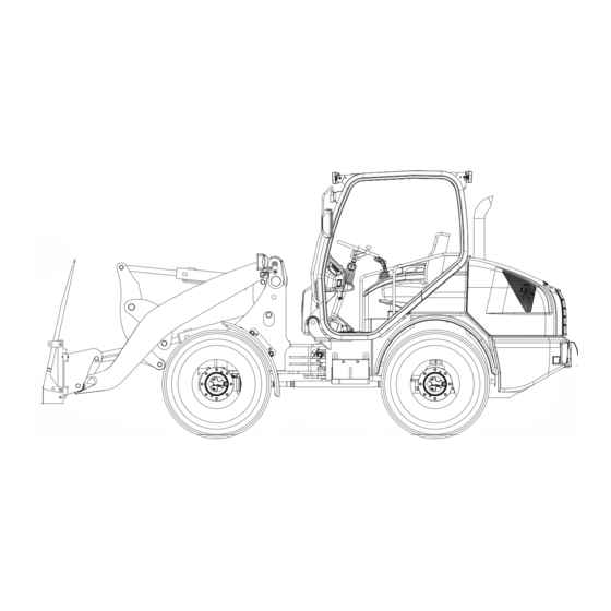
Page 76: General View Of The Machine
3.1 General view Operation General view 3.1.1 General view of the machine WA70-7 – VENAM02003... - Page 77 Operation 3.1 General view Bucket Tipping lever Front wheel Bucket cylinder Front work lights Warning beacon ROPS cab Rear wheel Turn signal Headlights Boom Lift cylinder Rear work lights Rear lights WA70-7 – VENAM02003...
-
Page 78: Controls
3.1 General view Operation 3.1.2 Controls General view 11 12 G0070202a.eps WA70-7 – VENAM02003... - Page 79 Speed range 2 switch 100% differential lock (option) Direction selector switch Multi-function lever Special equipment control lever E.C.S.S. switch (option) Auto-inch (option) Starting switch Cigarette lighter Car radio (option) Speed regulator (option) Work equipment lock lever Engine shutdown secondary switch WA70-7 – VENAM02003...
-
Page 80: Machine Monitor
3.1 General view Operation 3.1.3 Machine monitor General view G0070400 WA70-7 – VENAM02003... - Page 81 Turn signal pilot lamp Seat belt caution lamp E.C.S.S. pilot lamp Rear window defroster pilot lamp Air cleaner caution lamp Engine oil pressure caution lamp Coolant temperature gauge Save button Programming button Service meter Speedometer Fuel gauge WA70-7 – VENAM02003...
-
Page 82: Switches
3.1 General view Operation 3.1.4 Switches General view G0070202a.eps G0070417 WA70-7 – VENAM02003... - Page 83 Speed range 2 switch Direction selector switch E.C.S.S. switch with pilot lamp (option)* Auto-inch (option) Starting switch Cigarette lighter Speed control (option) Battery main switch Cab light switch Engine shutdown secondary switch (*) E.C.S.S.: (Electrically Controlled Suspension System) WA70-7 – VENAM02003...
- Page 84 Gauges Caution lamps All elements needed for the efficient operation of the machine are explained below. Pilot lamps This group includes the pilot lamps for high beam, glow plugs, turn indicators, direction selector switch, E.C.S.S. (optional). 3-10 WA70-7 – VENAM02003...
-
Page 85: Caution Lamps
If this is the case, you have to drain the water from the water separator. For details see “Water separator – draining water and dirt accu- mulations” (3-55). G0070206 3-11 WA70-7 – VENAM02003... - Page 86 This lamp lights up if the air cleaner becomes clogged when the engine is running. If this is the case, clean or replace the air cleaner cartridge. For details see “Changing the filter insert of the air cleaner, changing the safety filter” (5-36). G0070211 3-12 WA70-7 – VENAM02003...
- Page 87 If the lamp does not go out when the engine is running, or if it lights up during operation and the acoustic warning signal sounds, there is a malfunction in the oil pressure circuit. For details see 4.6 “Other troubles” (4-12). G0070421A 3-13 WA70-7 – VENAM02003...
-
Page 88: Pilot Lamps
3.2 Descriptions of the individual elements Operation Pilot lamps G0070400 3-14 WA70-7 – VENAM02003... - Page 89 It goes out when the pre-heating is completed. It is now possible to start the engine. If the coolant temperature is below 60 °C, the lamp lights up again for a maximum of 1 minute after the engine has started. G0070215 G0070421A 3-15 WA70-7 – VENAM02003...
- Page 90 If the turn indicator circuit is interrupted, the lamp flashes more quickly. GK100837 6. E.C.S.S. pilot lamp (Option) The E.C.S.S. lamp in the machine monitor lights up if the E.C.S.S. is engaged and the machine is travelling at a speed higher than 5 km/h. G0070214 3-16 WA70-7 – VENAM02003...
- Page 91 This lamp lights up when the auto-inch function is switched on. Pressing the switch again turns off the auto-inch function, and the lamp goes out. G007040 9. Hazard warning light pilot lamp This lamp flashes when the hazard warning lights are active. GK100815 3-17 WA70-7 – VENAM02003...
-
Page 92: Gauges
The background light is red when the fuel level is low. Refill fuel. If only the two bars at the right of the fuel display are lit, there is no electrical contact between the fuel display and the tank level sensor. In this event, contact your Komatsu distributor. G0070421A 3-18... - Page 93 The acoustic warning signal sounds. G0070271 The two buttons are for setting the tyre size and changing the speedometer display from “km/h” to “mph” and vice versa. NOTICE Have your Komatsu distributor adjust these settings! G0070407 3-19 WA70-7 – VENAM02003...
- Page 94 3.2 Descriptions of the individual elements Operation 3.2.2 Switches G0070202a.eps G0070417 3-20 WA70-7 – VENAM02003...
- Page 95 Speed range 2 switch Direction selector switch E.C.S.S. switch with pilot lamp (option)* Auto-inch (option) Starting switch Cigarette lighter Speed control (option) Battery main switch Cab light switch Engine shutdown secondary switch (*) E.C.S.S.: (Electrically Controlled Suspension System) 3-21 WA70-7 – VENAM02003...
- Page 96 If the switch is held in position '2', the washer stays active as long as the switch is held. G0070425 4. Programming button This switch can be used to set the type and dimension of the tyres. 3-22 WA70-7 – VENAM02003...
- Page 97 Use this switch to turn the rear window defroster on and off. The pilot lamp on the machine monitor lights up when the rear window defroster is switched on. G0070429 8. Warning beacon switch (Option) Use this switch to turn the warning beacon on and off. G0070431 3-23 WA70-7 – VENAM02003...
- Page 98 High-beam pilot lamp on Position 2 + 4 = Low beam on Position 2 + 5 = High beam on High-beam pilot lamp on G0070268 11. Horn button Use the horn button to sound the horn. GK100822 3-24 WA70-7 – VENAM02003...
- Page 99 For details see 6. “Control lever for special equipment and addi- tional function” (3-35). 15. Blower switch Use this rotary switch to control the airflow in several levels. Position 1 Blower off Position 2 Low airflow Position 3 Medium airflow Position 4 High airflow 3-25 WA70-7 – VENAM02003...
- Page 100 As long as lamp (1) is lit, the machine is operating in speed range 2. Pressing and releasing button (2) again causes the machine to return to speed range 1, and lamp (1) goes out. G0070213 3-26 WA70-7 – VENAM02003...
- Page 101 When the hydraulic back pressure in the work equipment is too high while loading, the tractive force of the drive is reduced until the work equipment can be raised again. NOTICE Always turn this switch off when driving on roads. G0070424 3-27 WA70-7 – VENAM02003...
- Page 102 (C) 'START' position With the switch in this position, the engine starts. NOTICE Starting the engine is possible only when the direction selector switch is in the neutral position, 'N'. G0070422 3-28 WA70-7 – VENAM02003...
- Page 103 (dial at '0') to fast (dial at '10'). Turn the dial to the right to increase the setting. Turn the dial to the left to decrease the setting. The conditions for use may differ G0070225 according to the condition of the road surface. 3-29 WA70-7 – VENAM02003...
- Page 104 Position (O): OFF The power supply is interrupted. The key can be removed in this position. Position (I): ON The power supply to the switching circuits is created. Ensure that this position is selected before starting the machine. 3-30 WA70-7 – VENAM02003...
- Page 105 (b) Normal: If normal (switch is pressed down) The switch is automatically returned to the normal position (b) when the cover is closed. Contact your Komatsu distributor as soon as possible to have the problem fixed. 3-31 WA70-7 – VENAM02003...
-
Page 106: Control Levers And Pedals
3.2.3 Control levers and pedals G0070201.eps Steering column adjustment Parking brake Brake pedal Accelerator pedal Multi-function lever Accessory control lever (3rd control circuit and electrical quick coupler) Work equipment lock lever Bucket switching lever (not figured) 3-32 WA70-7 – VENAM02003... - Page 107 Accident hazard through non-intended use of brake – do not use the brake pedal as a footrest. The brake is actuated with a combined inching and brake pedal. Inching provides an additional braking effect in the hydrostatic traction drive. 3-33 WA70-7 – VENAM02003...
- Page 108 (in emergencies). å Hold The boom is held in position. ã Lift The boom is raised. ä Tilt This position causes the bucket to tilt. à Dump This position causes the bucket to dump. 3-34 WA70-7 – VENAM02003...
- Page 109 Do not move the special equipment control lever to positions '1', '2' or '3' with no additional equipment attached. This would cause the work equipment to operate against overpressure and heat the oil unnecessarily, possibly damaging the hydraulic com- ponents in the long term. 3-35 WA70-7 – VENAM02003...
- Page 110 7. Work equipment lock lever The work equipment lock lever secures the work equipment against unintended use. Use this lock lever to lock the work equipment before driving on roads and prior to maintenance work. G0070233_2 3-36 WA70-7 – VENAM02003...
-
Page 111: Steering Lock
Insert the bolt (2) and secure it with the locking pin. 3.2.5 Tow hitch Use the tow hitch e.g. for towing another machine. Always secure the bolt of the tow hitch with the locking pin attached to the chain. 3-37 WA70-7 – VENAM02003... -
Page 112: Power Outlet
To be able to close the door (2) again, pull back the corresponding release mechanism. 3.2.8 Back-up alarm The back-up alarm sounds when the direction selector lever is in the reverse position. 3-38 WA70-7 – VENAM02003... -
Page 113: Fuses
Always replace defective fuses with fuses of the same rat- ing. The fuses protect the electrical system. Replace defective, cor- roded, or loose fuses. The fuses can be seen when the panel on the right side of the cab is opened. 3-39 WA70-7 – VENAM02003... - Page 114 3.2 Descriptions of the individual elements Operation Fuse allocation 3-40 WA70-7 – VENAM02003...
- Page 115 Switch for rear window wiper F4.3 10 A Heated seat F4.4 10 A Quick coupler, differential lock F4.5 10 A Speed control F4.6 10 A Central lubrication system F4.7 Fourth control circuit F4.8 10 A Option 3-41 WA70-7 – VENAM02003...
-
Page 116: Slow-Blow Fuses
1. Starter motor relay 2. Battery fuse 100 A 12 Ω 3. Intake air pre-heater relay K238 4. Intake air pre-heater fuse 100 A K106 32 Ω 5. Battery relay 6. Pilot lamp, controller K238 100A G0070264A 3-42 WA70-7 – VENAM02003... -
Page 117: Relays
The airflow may be directed with the diffuser discs. The upper, round air outlet nozzles can be directed at the windscreen and at the side windows. Air outlet nozzles Air intake nozzles G0070280A 3-43 WA70-7 – VENAM02003... - Page 118 To cool down the cab, open all air outlet nozzles and close the air intake nozzles (b). Then set rotary switch 2 to 'cold', and set the fan to the highest speed. 3-44 WA70-7 – VENAM02003...
-
Page 119: Air Conditioner
You can open and close all air outlet nozzles (a) individu- ally. The airflow may be directed with the diffuser discs. The air outlet nozzles (a) can be directed at the wind- screen and at the side windows. G0070280A 3-45 WA70-7 – VENAM02003... -
Page 120: Checks Before Starting
Completely remove dust and dirt. 3. Check engine area for water or oil leaks Check that the engine does not leak oil and verify that the coolant and fuel systems do not leak. Repair defects. 3-46 WA70-7 – VENAM02003... - Page 121 Check the belt, the belt lock, and the mounting points. Replace the seat belt if the belt, its lock, or the mounting points are damaged. Check the fixing screws of the mounting points for firm seat. 3-47 WA70-7 – VENAM02003...
- Page 122 3.3 Operation Operation 12. Check ROPS Check for loose or damaged screws. Have any screws retightened or replaced by a Komatsu distributor. Always retighten loose screws to the specified torque. Always replace damaged screws with original parts. 13. Check cab windows Clean cab windows before beginning to work.
-
Page 123: Checks Before Starting The Engine
4. Add coolant until the MAX mark is reached. 5. Firmly tighten the lid after adding coolant. 6. If the expansion tank becomes empty again after a short period of time, immediately have the cooling system checked for leakage and repaired at a workshop. 3-49 WA70-7 – VENAM02003... - Page 124 Entry of water may cause engine damage. Do not hold the compressed-air or water nozzle too close to the radiator fins. Do not use a brush for cleaning, as it may damage the radiator fins. 3-50 WA70-7 – VENAM02003...
- Page 125 Lateral cracks across the width of the belt are acceptable. Longitudinal cracks along the length of the belt that intersect with lateral cracks, missing pieces, or damage to the fabric layers are not acceptable. Replace the drive belt in this case. 3-51 WA70-7 – VENAM02003...
- Page 126 4. Wait for three minutes and check the oil level again. Drain some oil if the oil level is above the (H) mark. For details see “Draining engine oil” (3-53). 5. Close the oil filler neck (2). 3-52 WA70-7 – VENAM02003...
- Page 127 4. Drain excessive oil. 5. Unscrew the drain hose (2) from the drain valve. This closes the drain valve. 6. Check the oil level again. 7. Reinstall the cap (1) on the drain valve. 3-53 WA70-7 – VENAM02003...
- Page 128 2. Check the fuel level at the fuel gauge. Fuel tank full Fuel tank empty 3. Turn the starting switch to the 'A' (OFF) position. G0070218 4. Add fuel as required. 5. Close the filler neck after refueling. 3-54 WA70-7 – VENAM02003...
- Page 129 2. Unscrew the valve (1) at the bottom of the water separator by 2 rotations. 3. Drain off water and dirt until pure fuel flows out. 4. Retighten the valve (1) again by turning clockwise. ATTENTION Do not over-tighten the valve, as this might damage the thread. 3-55 WA70-7 – VENAM02003...
- Page 130 5. Loosen the bleed screw (2) on the injection pump. 6. Work the pump button (3) on the fuel filter until there are no more bubbles in the fuel flowing from the bleed screw. 7. Retighten the bleed screw (2). 3-56 WA70-7 – VENAM02003...
- Page 131 Remove combustible material from the electrical system. NOTICE Contact your Komatsu distributor if a fuse blows or if there are signs to indicate a short circuit in the electrical system. Periodically check the terminals for firm seat and retighten loose terminals.
- Page 132 Other maintenance tasks to perform before starting. Check lights for function, dirt, and damages. Check gauges. Check horn and back-up alarm. Check steering play and function. Check rear-view mirrors for function, dirt, and damages. 3-58 WA70-7 – VENAM02003...
-
Page 133: Adjustments Before Starting
Apply weight to the rear of the seat to lower Release lever (4) when reaching the desired height. The seat will lock in this position. Angle adjustment Adjust the front and rear of the seat differently. Proceed as described in the above chapter. 3-59 WA70-7 – VENAM02003... - Page 134 Take load off the backrest to tilt it forward. Press the back- rest to the rear to tilt it backward. Release lever (5) when the backrest has reached the desired position. The backrest will lock in this position. 3-60 WA70-7 – VENAM02003...
- Page 135 Release lever (3) when the backrest has reached the desired position. The backrest will lock in this position. 5. Adjusting the headrest Move the headrest up or down. 3-61 WA70-7 – VENAM02003...
- Page 136 3. Retighten the screw. Adjusting the rear-view mirrors Sit in the operator's seat and adjust the rear-view mirrors as desired. You should be able to observe the following traffic with- out having to lean forward or backward. 3-62 WA70-7 – VENAM02003...
- Page 137 4. Pull the belt to check that the tongue is locked properly. NOTICE The belt cannot be pulled out unless it is completely wound up. Taking off the seat belt Press the orange button to open the seat belt lock, and allow the belt to wind up. 3-63 WA70-7 – VENAM02003...
-
Page 138: Starting The Engine
6. Release the starting switch as soon as the engine starts. It automatically returns to its operating position 'B' (ON). 7. When the coolant temperature is below 60 °C, the pilot lamp lights up again for a maximum of 1 minute after the engine has started. 3-64 WA70-7 – VENAM02003... -
Page 139: Ambient Temperature For Operation And Storage
For details see 3.5 “Operation in cold weather” (3-105). Ambient temperature for operation and storage The recommended ambient temperature for operation and stor- age is between -20°C and +45°C. For ambient temperatures under 0°C see 3.5 “Operation in cold weather” (3-105). 3-65 WA70-7 – VENAM02003... -
Page 140: Checks After Starting The Engine
3. Check that the exhaust colour is normal and that the exhaust pipe does not vibrate or sound abnormally. Repair any defects. 4. Do not work under full load before reaching the operating temperature. The coolant temperature gauge (1) must be in the green. 3-66 WA70-7 – VENAM02003... -
Page 141: Driving The Machine
2. Raise the work equipment to the carrying position. 3. Engage the work equipment lock lever. 4. Depress and hold the brake pedal. G0070233_2 5. Release the parking brake. The parking brake caution lamp goes out. 3-67 WA70-7 – VENAM02003... -
Page 142: Limiting The Maximum Speed
6. Lock the speed regulator against being adjusted unintention- ally by moving the locking device (2) all the way to the right stop. NOTICE Depending on the road surface, identical speed regulator set- tings may result in different speeds. 3-68 WA70-7 – VENAM02003... - Page 143 5. Set the direction selector switch to the desired direction. Position F Forward Position N = Neutral position Position R = Reverse 6. Depress the accelerator pedal and slowly release the brake pedal simultaneously to start the machine. 3-69 WA70-7 – VENAM02003...
-
Page 144: Changing Direction
The machine can travel as fast in reverse as forward. Look to the rear of the machine when driving in reverse; do not just orient yourself with the rear-view mirrors. Before travelling, sound the horn to warn people in the area. 3-70 WA70-7 – VENAM02003... -
Page 145: Turning And Steering
To keep the centre of gravity low, keep the bucket close to the ground (approx. 20–30 cm) when driving on slopes, ridges or embankments. In case of an emergency, quickly lower the bucket on the floor to stabilise the machine. 3-71 WA70-7 – VENAM02003... -
Page 146: Brakes
(3). (This is called inching.) If you need to fully depress the accelerator pedal to use the full engine power for the work equipment, you may still use the brake pedal to lower the ground speed or stop the machine. 3-72 WA70-7 – VENAM02003... -
Page 147: If The Service Brake Fails
If the service brake is used excessively when driving downhill, it may overheat and become damaged. Prevent this by driving downhill slowly and using the braking force of the engine. 3-73 WA70-7 – VENAM02003... -
Page 148: Stopping And Parking The Machine
If it is necessary to park the machine on a slope, position the machine with the work equipment facing downhill. Apply the parking brake. Lower the work equipment (1) to the ground. Block the wheels with wheel chocks (2). 3-74 WA70-7 – VENAM02003... -
Page 149: Operating The Work Equipment
(in emergencies). å Hold The boom is held in position. ã Lift The boom is raised. ä Tilt This position causes the bucket to tilt. à Dump This position causes the bucket to dump. 3-75 WA70-7 – VENAM02003... -
Page 150: Return To Dig
4. After adjusting, start the engine and raise the boom. Set the bucket control lever to DUMP and then to TILT BACK. The control lever should lock in a detent. Check that the lever automatically returns to HOLD when the bucket has reached the desired digging angle. 3-76 WA70-7 – VENAM02003... -
Page 151: Working With The Wheel Loader
To prevent the front wheels from slipping, they should press into the ground as much as possible. Therefore, slightly raise the bucket as soon as it enters the stockpile. 3-77 WA70-7 – VENAM02003... - Page 152 If only one wheel of an axle is turning when starting from a stop, stop and correct the steering until the lock engages properly. To disengage the differential lock, release button (1) on the multi-function lever. The differential lock can be disengaged while driving. 3-78 WA70-7 – VENAM02003...
-
Page 153: Loading
4. Inch the machine with the service brake while keeping the accelerator pedal depressed. 5. Depress the accelerator pedal and dig the bucket into the material. For digging loose material, hold the bucket's cutting edge level when pushing into the material. 3-79 WA70-7 – VENAM02003... - Page 154 Raising the boom provides a sufficient amount of traction. 7. Tilt the bucket. 8. If the bucket is too full, quickly tilt, dump, and lower the bucket to reduce the load and prevent the load from spilling while carrying. 3-80 WA70-7 – VENAM02003...
-
Page 155: Excavating
5. Slightly wiggle the multi-function lever for the boom up and down to reduce the resistance when driving the machine for- ward. When digging, check that the digging force does not act une- venly on the bucket. 3-81 WA70-7 – VENAM02003... -
Page 156: Levelling
Always drive in the lower speed range when scraping. NOTICE Scraping with the bucket in the dumping position damages the bucket and the teeth. Align the bottom of the bucket level with the ground when scraping. 3-82 WA70-7 – VENAM02003... -
Page 157: Carrying
Keep the bucket tilted in. Lower the boom to the carrying position. For details see “Saving the tyres” (3-77). NOTICE Set the work equipment to the carrying position before moving it to the tilting stop. 3-83 WA70-7 – VENAM02003... - Page 158 Raise the bucket to its maximum height. Drive forward towards the dump lorry and unload the material. The smaller the turning angle of the machine, the more effi- ciently you are working. 3-84 WA70-7 – VENAM02003...
-
Page 159: Working With The Forklift Attachment
Raise the boom to the desired unloading height shortly before reaching the location of unloading. This pre- vents the load from becoming damaged while lifting. Keep the forklift attachment horizontal when stacking, if pos- sible. 3-85 WA70-7 – VENAM02003... - Page 160 7. Slowly lower the boom until it is possible to pull the tines out from under the load. 8. Check that there are no persons standing behind the machine, and back up from the unloading location. 3-86 WA70-7 – VENAM02003...
-
Page 161: Operating Precautions
Working on loose ground Follow the instructions in section “Working on loose ground” (2-28). If the service brake fails If the machine does not stop even when the brake pedal is fully depressed, you must use the parking brake. 3-87 WA70-7 – VENAM02003... -
Page 162: Precautions For Driving Uphill Or Downhill
The required tyre pressure, the ground speed, and the type of tyre vary depending on the road conditions. Contact your Komatsu distributor or your tyre distributor for related infor- mation. See table “Tyres and tyre pressure” in chapter “Tyre pres- ... -
Page 163: Adjusting The Work Equipment
5. Drive the machine towards the work equipment until the quick coupler (a) is underneath the mounting hooks of the work equipment. Then raise the boom until the work equip- ment is suspended from the quick coupler. 7 5 _ 2 8 0A 3-89 WA70-7 – VENAM02003... - Page 164 WARNING If the work equipment is not locked properly, it may drop sud- denly and cause serious accidents. 8. Check the work equipment for proper attachment by tilting and dumping. 7 5 _ 2 8 0A 3-90 WA70-7 – VENAM02003...
- Page 165 Position 2 Close multi-purpose bucket WARNING If the work equipment is not locked properly, it may drop sud- denly and cause serious accidents. 13. Check the multi-purpose bucket for proper attachment by tilt- ing and dumping. 3-91 WA70-7 – VENAM02003...
-
Page 166: Removing The Work Equipment
'A', until the quick coupler disengages from the mounting hooks of the work equipment. 4. Check that there are no persons standing behind the machine, and back up the machine from the work equip- ment. 3-92 WA70-7 – VENAM02003... -
Page 167: Removing The Multi-Purpose Bucket
They are parallel with the cut- ting edge. The level indicators inform the operator of the position of the cut- ting edge when the operator is sitting in the operator's seat. 3-93 WA70-7 – VENAM02003... -
Page 168: Switching Off The Engine
Also check for oil and water leakage. Immediately repair any defects. 2. Fill the fuel tank. 3. Remove combustible material from the engine area, as it is a fire hazard. 4. Remove coarse dirt from the undercarriage. 3-94 WA70-7 – VENAM02003... -
Page 169: Locking
Operation 3.3 Operation 3.3.15 Locking Lock at the following locations: Engine bonnet Cab door NOTICE The ignition key fits all locks. 3-95 WA70-7 – VENAM02003... -
Page 170: Handling Tyres
Remove nails, chunks of metal, and other foreign particles from the tyres. Remove fallen rocks from the working area. Clearing the work- space prolongs the service life of the tyres and increases the profitability of the machine. 3-96 WA70-7 – VENAM02003... -
Page 171: Standard Tyres
The specified air pressure values might deviate from the stand- ard values under special conditions. If this is the case, please contact an authorised Komatsu distributor. The service life and performance of the tyres is depends criti- cally on the proper pressure. Proper pressure protects the tyres against damage. -
Page 172: Transporting Procedure
There is risk of the machine losing its balance. Always drive slowly over this point. When loading or unloading, always use ramps or a platform. Proceed as follows: 3-98 WA70-7 – VENAM02003... -
Page 173: Loading The Machine
GK032225 If the ramp sags noticeably, reinforce it with blocks or similar. 3. Determine the direction of the ramp, then slowly load the machine. 4. Load the machine correctly in the specified position on the trailer. 3-99 WA70-7 – VENAM02003... -
Page 174: Securing The Machine
3. Lower the work equipment to the ground. 4. Engage the work equipment lock lever. G0070233_2 5. Lock the articulated steering with the locking bolt (right side: 1). For details see “Securing the articulated steering” (2-37). 3-100 WA70-7 – VENAM02003... - Page 175 To avoid damaging the machine, only fasten the hooks of the fastening ropes to the marked attachment points on the machine as shown in the diagram on the right. Chains or ropes must not contact other components. 7. Always retract the car radio antenna fully. G0070240 3-101 WA70-7 – VENAM02003...
-
Page 176: Unloading The Machine
6. Engage the work equipment lock lever. 7. Depress the brake pedal and release the parking brake. Keep the right brake pedal depressed. 8. Determine the direction of the ramp, then slowly unload the machine. G0070233_2 3-102 WA70-7 – VENAM02003... -
Page 177: Lifting The Machine
This lifting procedure applies to machines with standard specifi- cations. The method of lifting differs according to the attach- ments and options actually installed. In such cases, please contact your Komatsu distributor for information. For details on the weight please see 6.1 “Technical data” (6-2). 3-103... - Page 178 10° (see illustration above) and must not touch any part of the machine aside from the attachment points. Lift the machine at these 4 points exclusively. There is a high risk of the machine losing its balance. GK032227 3-104 WA70-7 – VENAM02003...
-
Page 179: Precautions For Operation In Cold Weather
When changing the coolant or when handling coolant con- taining antifreeze that has been drained while repairing the radiator, please contact your Komatsu distributor. Antifreeze is toxic. Prevent it from leaking into drainage ditches or spill- ing on the ground. -
Page 180: Precautions After Work
When season changes and the weather becomes warmer, do as follows: Change the fuel. Replace the oil for all components with oil of the specified viscosity. For details see 5.4 “Fuel, lubricants, and coolants; quantities” (5-18). 3-106 WA70-7 – VENAM02003... -
Page 181: Before Storage
Remove the key to the battery main switch. Keep the battery covered in storage. Lock all control levers with the lock levers. To prevent corrosion, fill the cooling system with original Komatsu Supercoolant (AF-NAC). Check that the mixing ratio is 30% at least. 3-107 WA70-7 – VENAM02003... -
Page 182: During Storage
Check the oil for accumula- tion of water before and after starting the engine. If there is water in the oil, change the oil. For lubricating the machine, see chapter 5.7 “Maintenance schedule” (5-24). 3-108 WA70-7 – VENAM02003... -
Page 183: Machines Equipped With Komtrax
Always contact your Komatsu distributor before selling or exporting any machine equipped with KOMTRAX. When selling or exporting the machine, or in other cases when your Komatsu distributor considers it necessary, it may be that the KOMTRAX unit needs to be removed or rendered inopera- ble. - Page 184 The KOMTRAX communications terminal does not need inspec- tion or maintenance. Consult your Komatsu distributor in case of anomalies. 3-110 WA70-7 – VENAM02003...
-
Page 185: Troubleshooting
Troubleshooting 4. Troubleshooting WA70-7 – VENAM02003... -
Page 186: Towing The Machine
On the front frame, the towing device has to be fastened to the marked towing eye. On the rear frame, the towing device can be fastened to the towing pin. Before towing: 1. Set the direction selector switch to “N”. WA70-7 – VENAM02003... - Page 187 Allen key by 2 rotations. Retighten the lock nut (2). Perform this task on both valves. 4. Tip down the operator's cab. For details see 5.1.2 “Tipping down the operator's cab” (5-5). WA70-7 – VENAM02003...
- Page 188 2. Put the protective caps on the valves. 3. Tip down the operator's cab. For details see 5.1.2 “Tipping down the operator's cab” (5-5). NOTICE When the engine is not running, the power steering is inactive. WA70-7 – VENAM02003...
- Page 189 Towing on even, level surfaces requires a low traction power while towing on slopes and on uneven surface requires high traction power. Contact your Komatsu distributor for further information on tow- ing a machine. WA70-7 – VENAM02003...
-
Page 190: Starting The Engine With Booster Cables
Remove the key to the battery main switch. WA70-7 – VENAM02003... - Page 191 4. Turn on the battery main switch (S) of the defective machine. Finally connect the other terminal of the booster cable (B) to the frame of the defective vehicle. 5. Let the engine run at high speed. WA70-7 – VENAM02003...
- Page 192 3. Disconnect the terminal of the booster cable (A) from the positive terminal (+) of the operational machine. Frame of the discharged battery GK100876A 4. Disconnect the other terminal of the booster cable (A) from the positive terminal (+) of the defective machine. WA70-7 – VENAM02003...
-
Page 193: In Case Of Insufficient Brake Power
5. Turn off the engine. 6. Engage the parking brake (2) and slowly release the brake pedal. The machine must remain steady. NOTICE All repairs of the brake system have to be performed by a Komatsu workshop. WA70-7 – VENAM02003... -
Page 194: Emergency Steering Properties
If the engine fails while you are driving, you can still steer the machine. However, you need to manually apply more power. In case of engine failure, immediately drive to the side of the road, switch on the warning lights and secure the machine. 4-10 WA70-7 – VENAM02003... -
Page 195: Emergency Lowering
G0070233_2 1. Make sure that no one is standing under the machine. 2. Push the multi-function lever slowly to the position “S”. The work equipment is lowered. 4-11 WA70-7 – VENAM02003... -
Page 196: Other Troubles
4.6 Other troubles Troubleshooting Other troubles 4.6.1 Electrical system If errors or causes of errors occur that are not listed here, have the repair performed by your Komatsu distributor. ELECTRIC SYSTEM Fault Cause Remedy Battery charge circuit caution lamp: The battery charge circuit caution lamp... -
Page 197: Engine
Troubleshooting 4.6 Other troubles 4.6.2 Engine If errors or causes of errors occur that are not listed here, have the repair performed by your Komatsu distributor. ENGINE Fault Cause Remedy Oil level in the engine is too low Add engine oil... - Page 198 Filter insert of the air cleaner Clean or replace the air cleaner filter The air cleaner caution lamp lights clogged insert up while the engine is running *) These tasks should be performed by the distributor. 4-14 WA70-7 – VENAM02003...
-
Page 199: Hydraulic System
Troubleshooting 4.6 Other troubles 4.6.3 Hydraulic system If errors or causes of errors occur that are not listed here, have the repair performed by your Komatsu distributor. HYDROSTATIC DRIVE UNIT Fault Cause Remedy Parking brake is engaged Disengage the parking brake Switch direction selector switch in Direction selector switch in “N”... - Page 200 *) Cylinder movements are jerky. Priority valve defective Check the priority valve; replace if necessary *) Directional valve defective Check the directional valve; replace if necessary *) *) These tasks should be performed by the distributor. 4-16 WA70-7 – VENAM02003...
- Page 201 Troubleshooting 4.6 Other troubles 4.6.4 Brakes If errors or causes of errors occur that are not listed here, have the repair performed by your Komatsu distributor. BRAKES Fault Cause Remedy Brake lining worn out Replace brake pads *) Brake disc worn out...
-
Page 202: Steering
4.6 Other troubles Troubleshooting 4.6.5 Steering If errors or causes of errors occur that are not listed here, have the repair performed by your Komatsu distributor. STEERING Fault Cause Remedy Hydraulic system is not working Check the function of the hydraulic... -
Page 203: Maintenance
Maintenance 5. Maintenance WA70-7 – VENAM02003... -
Page 204: Maintenance Guide
Set the multi-function lever to the '0' position, HOLD. Engage the work equipment lock lever. Apply the parking brake. Secure the articulated steering with the locking bolt. Block the wheels with wheel chocks. G0070233_2 WA70-7 – VENAM02003... -
Page 205: Tipping Up The Operator's Cab
6. Remove locking pins (1) and loosen the retaining screws (2) for the cab on both sides. 7. Take the hand pump lever from its holder on the radiator (3) and insert it into the receptacle of the pump (4). WA70-7 – VENAM02003... - Page 206 10. Set the lever at the pump to “pump down” and pump the cab downward until the safety rod is secure against the right side of the cab floor. G0070278 11. Remove the lever from the pump. WA70-7 – VENAM02003...
-
Page 207: Tipping Down The Operator's Cab
3. Set the lever to “pump down” and pump the cab downward until the cylinder is entirely retracted (the resistance at the lever increases markedly). G0070278 4. Remove the lever from the pump and fasten it to the radiator. WA70-7 – VENAM02003... - Page 208 Komatsu genuine replacement parts: Use Komatsu genuine parts specified as replacement parts in the Parts Book. In order to ensure safe assembly and operation of the machine, it is recommended that you use Komatsu genu- ine parts. Komatsu genuine oils: Use Komatsu genuine oils and grease.
- Page 209 Clean electrical components, especially the starter motor and alternator, to prevent accumulation of dust. When inspecting or changing the oil, move the machine to a place that is free of dust to prevent oil contamination. WA70-7 – VENAM02003...
- Page 210 Be careful not to forget to install the o-rings and seals. When installing the hoses, do not twist them or bend them into loops with a small radius. This will cause damage to the hose and markedly reduce its service life. WA70-7 – VENAM02003...
- Page 211 If any control lever must be operated, give a signal to the other workers to warn them to move to a safe place. Increase the engine speed to check for fuel and oil leak- age. WA70-7 – VENAM02003...
-
Page 212: Basic Maintenance Guidelines
Engine oil pan EO15W40DH engine oil (Komatsu genuine parts) Transmission case Shell Spirax S4 TXM Shell Tellus S2 M46 hydraulic oil (Komatsu genuine parts) Serial numbers from H62051 to H62383 Hydraulic system Engine oil EO10W30-DH (Komatsu genuine parts) Serial numbers from H62384... -
Page 213: Fuel, Coolant And Lubricant Specifications
Komatsu distributor. When using commercially available oil, it may be necessary to reduce the oil change interval. We recommend using the Komatsu oil clinic for a detailed check of the oil characteristics. 5-11 WA70-7 – VENAM02003... -
Page 214: Fuel
If there is any foreign material in the fuel tank, flush the tank and the fuel system. NOTICE Exclusively use diesel fuel. Never use any other fuel. Using low- viscosity fuel with poor lubricating characteristics will cause a marked reduction in the durability of the engine. 5-12 WA70-7 – VENAM02003... -
Page 215: Coolant
NAC) exclusively. Using any other coolant may cause seri- ous damage such as corrosion of the engine or of cooling system components that use light metals like aluminium. When using Komatsu Supercoolant (AF-NAC) there is no need to use anti-corrosive. -
Page 216: Grease
To prevent deterioration of the quality during storage, be sure to use fuels and lubricants in the order of first in – first out (use the oldest oil or fuel first). 5-14 WA70-7 – VENAM02003... -
Page 217: Filters
Biodegradable hydraulic oil and lubricants The use of biodegradable hydraulic oils and lubricants based on synthetic esters with Komatsu machines is permitted. For infor- mation on products cleared for use and best suited for your application, please contact your Komatsu distributor. -
Page 218: Outlines Of The Electrical System
Komatsu. External electro-magnetic interference may cause a mal- function of the system controller. Please contact your Komatsu distributor before installing a radio receiver or other wireless equipment. When working close to the sea, carefully clean the electrical ... -
Page 219: Wear Parts List
5.3.1 Wear parts list The parts in parentheses need to be replaced at the same time. *: Order numbers for the parts: See the Parts Book (Komatsu). Item Part no. Part name Quantity... -
Page 220: Fuel, Lubricants, And Coolants; Quantities
5.4 Fuel, lubricants, and coolants; quantities Maintenance Fuel, lubricants, and coolants; quantities 5.4.1 Lubrication table G0070230 Lubricate with grease (G) Change filter Check/change oil (EO) The maintenance schedule in the Operation and Maintenance Manual is binding, see 5.7 “Maintenance schedule” (5-24). 5-18 WA70-7 – VENAM02003... - Page 221 The upper and lower temperature limits are guidelines; exceeding for a short time is permissible. ) Factory filling ) If using fuels with a sulphur content between 0.5 to 1.0 %, reduce the engine oil change intervals by half. Note 1: Supercoolant (AF-NAC) For details see “Coolant” (5-13). 5-19 WA70-7 – VENAM02003...
- Page 222 5.4 Fuel, lubricants, and coolants; quantities Maintenance Tank capacity Specification (litres) Refill amount Engine oil pan Transmission Hydraulic system Front and rear axles (per axle) Planetary gear: 2× 0.7 Differential: Brakes Cooling system Fuel tank Air conditioner 1200 g 5-20 WA70-7 – VENAM02003...
-
Page 223: Recommended Brands, Recommended Quality For Products Other Than Komatsu Genuine Oil
5.4 Fuel, lubricants, and coolants; quantities Maintenance 5.4.2 Recommended brands, recommended quality for products other than Komatsu genuine oil Please contact your Komatsu distributor when using commer- cially available oils other than Komatsu genuine oil. 5-21 WA70-7 – VENAM02003... -
Page 224: Tools
24/27 mm Screwdriver 421-98-H1120 – Screwdriver 421-98-H1110 – Grease pump 424-98-H1010 – Hose 424-98-H1020 Grease pump hose Grease cartridge 07950-90403 Lithium grease: 400 g Hammer 421-98-H1140 – 421-98-H1130 – Re-order damaged parts from your Komatsu distributor. 5-22 WA70-7 – VENAM02003... -
Page 225: Periodic Replacement Of Safety-Critical Parts
These parts are particularly important for safety and fire prevention. Please contact your Komatsu distrib- utor to have them replaced. The material quality of these parts can change as time passes, and they are likely to wear out or deteriorate. - Page 226 Maintenance every 500 service hours 5-50 Manual pump – check oil level 5-50 Service brake – check brake pads and brake disc, check oil level 5-51 Engine – change engine oil 5-52 Changing the oil filter cartridge 5-53 5-24 WA70-7 – VENAM02003...
- Page 227 Cooling system – change coolant and clean cooling system 5-67 Valve clearance – check and adjust 5-70 Hydraulic system – change hydraulic oil 5-71 Check fuel pump 5-73 Fuel and coolant hoses – check, replace if required 5-73 Checking the water pump 5-73 5-25 WA70-7 – VENAM02003...
- Page 228 Heating/air conditioner – check airflow Check lights for function, dirt, and damages. Check gauges. Check horn and back-up alarm. Check steering play and function. Check rearview mirror for function, dirt, and damages. 5-26 WA70-7 – VENAM02003...
- Page 229 5. Change filter insert, if it is dirty or damaged. 6. Reinstall the glass container and hand-tighten the collar nut. 7. Open the stop valve (A) by turning the lever downward. 8. Bleed the fuel system. For details see “Bleeding the fuel system” (5-55). 5-27 WA70-7 – VENAM02003...
- Page 230 Do not touch the refrigerant. Never loosen any parts of the coolant circuit. When working on the air conditioning system, wear protec- tive goggles and rubber gloves. 5-28 WA70-7 – VENAM02003...
- Page 231 Oil and refrigerant are separated; liquid is a thin, milky white. Operating the air conditioner off-season Even during the off-season, operate the air conditioner for 3–5 minutes once a month to maintain the oil film at all parts of the compressor. 5-29 WA70-7 – VENAM02003...
- Page 232 Damage to the electrode plates Do not swap the wires (positive (+) and negative (-)). For maintenance, disconnect the wires from the battery termi- nals, except when checking the battery fluid level or measuring the specific density. 5-30 WA70-7 – VENAM02003...
- Page 233 Clean the air grilles from both sides if they are dirty. NOTICE Do not use a high-pressure cleaner to clean the air grilles. Cleaning the radiator fins Clean the radiator fins when they are dirty. For details see “Radiator – clean radiator fins” (3-50). 5-31 WA70-7 – VENAM02003...
- Page 234 If the air cleaner caution lamp (1) lights up, the air cleaner insert is clogged. Clean or replace it immediately. Dirt in the safety filter indicates a damaged filter insert. In this case, the filter insert and the safety filter need to be replaced. G0070400A 5-32 WA70-7 – VENAM02003...
- Page 235 2. Open the bayonet lock of the air cleaner cap (2). 3. Remove the cover of the air cleaner housing. 4. Pull out the filter insert (3). 5. Thoroughly clean the inside of the air cleaner housing with a cloth. 5-33 WA70-7 – VENAM02003...
- Page 236 Move the insert back and forth in the solu- tion. Then flush the filter insert from the inside to the outside with clean water (max. 3 bar) and dry at a maximum temperature of 50 °C. 5-34 WA70-7 – VENAM02003...
- Page 237 If the air cleaner caution lamp lights up again after a short time, replace both the filter insert and the safety filter. For details see “Changing the filter insert of the air cleaner, changing the safety filter” (5-36). 5-35 WA70-7 – VENAM02003...
- Page 238 3. Pull out the safety filter (2). 4. Check the new air cleaner for damage by shining a light through it. Firmly install the safety filter. 5. Install the filter insert. 5-36 WA70-7 – VENAM02003...
- Page 239 1. Check for loose nuts, and tighten if necessary. When checking for loose nuts, always turn the nuts in the direction of tightening. Torque: 450–500 Nm 2. If any stud bolt is broken, replace all the stud bolts for that wheel. 5-37 WA70-7 – VENAM02003...
- Page 240 2. Clean the indicated grease nipple. 3. Use a grease pump to press a sufficient amount of grease into the grease nipples. 4. Remove any excess old grease that is pushed out at the bearings. Rear axle pivot bearing (1) (2). 5-38 WA70-7 – VENAM02003...
- Page 241 Maintenance after the first 250 service hours Carry out the following maintenance only after the first 250 ser- vice hours. Valve clearance – check and adjust Have the valve clearance checked and adjusted by a Komatsu distributor. 5.8.5 Maintenance after the first 500 service hours Carry out the following maintenance only after the first 500 ser- vice hours.
- Page 242 3. Use a grease pump to press a sufficient amount of grease into the grease nipples. 4. Remove any excess old grease that is pushed out at the bearings. NOTICE Shorten the maintenance intervals if working continuously in wet or salty environments. 5-40 WA70-7 – VENAM02003...
- Page 243 -10 °C -25 °C Charging level Specific density (kg/l) full 1.28 1.29 1.30 1.31 half 1.20 1.21 1.22 1.23 empty 1.12 1.13 1.14 1.15 6. Recharge insufficiently charged batteries. 7. Plug the cells with clean stoppers. 5-41 WA70-7 – VENAM02003...
- Page 244 4. Remove any excess old grease that is pushed out at the bearings. WA70-7 Tilt rod (2 points) Multi-purpose bucket (6 points) Upper and lower lift cylinders (2 points) Tilt arm (2 points) Left and right boom (4 points) Tilt cylinder (2 points) 5-42 WA70-7 – VENAM02003...
- Page 245 5.8 Maintenance procedure Maintenance Maintenance every 50 service hours G0070248 G0070247 5-43 WA70-7 – VENAM02003...
- Page 246 Visual inspection of the state of lubrication of the bearings and observation of the lubrication pattern. In the event of fault indications, consult your Komatsu distributor to rectify the fault. NOTICE Only refill using clean lubricant and a suitable filling device (A or B).
- Page 247 1. For maintenance work, park and secure the machine as described in chapter 5.1 “Maintenance guide” (5-2). 2. Check brake disc and brake pads for wear and damages. 3. Check the brake oil level. 5-45 WA70-7 – VENAM02003...
- Page 248 5. Loosen the retaining screw (3) of the guide rail. 6. Adjust the v-belt tension by angling the alternator. 7. Fix the alternator and the guide rail. 8. Check the v-belt tension and readjust if required. 5-46 WA70-7 – VENAM02003...
- Page 249 3. Use a grease pump to press a sufficient amount of grease into the grease nipples. 4. Remove any excess old grease that is pushed out at the bearings. Front steering cylinder (1 point) Rear steering cylinder (1 point) 5-47 WA70-7 – VENAM02003...
- Page 250 2. Clean the indicated grease nipple. 3. Use a grease pump to press a sufficient amount of grease into the grease nipples. 4. Remove any excess old grease that is pushed out at the bearings. Rear axle pivot bearing (1) (2). 5-48 WA70-7 – VENAM02003...
- Page 251 5.8 Maintenance procedure Maintenance Maintenance every 250 service hours Wheel nuts – check and retighten For details see “Wheel nuts – check and retighten” (5-37). 5-49 WA70-7 – VENAM02003...
- Page 252 3. The oil level should be at the lower edge of the filling hole (arrow). 4. Add oil if required. For details see 5.4 “Fuel, lubricants, and coolants; quanti- ties” (5-18). 5. Insert the screw plug into the filling hole and fasten finger- tight. G0070267 5-50 WA70-7 – VENAM02003...
- Page 253 2. Check the brake fluid level at the expansion tank. The oil level should be between the “MIN” and “MAX” marks. 3. If the oil level is too low, have the brake system inspected. 4. Check brake disc and brake pads for wear and damages. 5-51 WA70-7 – VENAM02003...
- Page 254 5. Drain the oil. 6. Inspect the drained oil: If the oil is contaminated with metal shavings or foreign particles, notify your Komatsu distributor. Unscrew the drain hose (2) from the drain valve. This closes the drain valve.
- Page 255 8. Re-check the oil level approx. ten minutes after switching off the engine. The oil level must be between the 'H' and 'L' marks on the dipstick. For details see “Check engine oil level – add engine oil” (3-52). 5-53 WA70-7 – VENAM02003...
- Page 256 (observe the instructions of the filter manufacturer). 12. Reconnect the connector (2) of the sensor (3). 13. Bleed the fuel system. For details see “Bleeding the fuel system” (5-55). 14. Start the engine and check for leakage. 5-54 WA70-7 – VENAM02003...
- Page 257 1. Loosen the bleed screw (1) on the injection pump. 2. Move the pump button (2) on the fuel filter until there are no more bubbles in the fuel flowing from the bleed screw. 3. Retighten the bleed screw (1). 5-55 WA70-7 – VENAM02003...
- Page 258 NOTICE All air outlet nozzles (a) and air intake nozzles (b) must be open! 7. Replace the filter cloth if the airflow is low. 8. Reinstall the front panel (1). G0070280A 5-56 WA70-7 – VENAM02003...
- Page 259 Checking the gas pressure in the pressure accumulator for the multi-function lever Have the gas pressure in the pressure accumulator checked by your Komatsu distributor every 500 service hours (gas pressure: 20 bar). E.C.S.S. pressure accumulator – check gas pressure...
- Page 260 2. Remove the screw plug (3) of the check bore at the rear axle. Check the oil level as described under “epicyclic gear- ing” in items 3. to 5. Torque (2) and (3) = 60 Nm 5-58 WA70-7 – VENAM02003...
- Page 261 5. If the oil level is too low, add oil through the check bore of the screw plug (1). 6. Clean the screw plug and install new sealing ring. 7. Insert the screw plug and tighten firmly. Torque (1) = 60 Nm 5-59 WA70-7 – VENAM02003...
- Page 262 5. Loosen the retaining screw (3) of the guide rail. 6. Adjust the v-belt tension by angling the alternator. 7. Fix the alternator and the guide rail. 8. Check the v-belt tension and readjust if required. 5-60 WA70-7 – VENAM02003...
- Page 263 Change brake oil. Check hoses and lines. Check brake disc and brake pads for wear and damages. System pressures – check and adjust Have the system pressures measured and adjusted by a Komatsu distributor. 5-61 WA70-7 – VENAM02003...
-
Page 264: Hydraulic System – Change Venting Filters
5. Unscrew the old filter (1) and o-ring. 6. Screw in a new filter (1) with o-ring, tighten by hand. 7. Do a trial run to check that the system is leak-free. 8. Screw the cover back onto the hydraulic tank. 5-62 WA70-7 – VENAM02003... -
Page 265: Hydraulic System – Change Filter Insert
15. Tighten the venting filter (1). 16. Start the engine. 17. Actuate the boom and bucket several times. 18. Check the hydraulic oil level. 19. Do a trial run to check that the system is leak-free. 5-63 WA70-7 – VENAM02003... -
Page 266: Maintenance Every 1500 Service Hours
6. Clean the screw plug and install an intact seal. 7. Insert the screw plug and tighten firmly. Torque (1) = 60 Nm 8. Change the oil on the other wheels at the front and rear axle as described in items 1. to 7. 5-64 WA70-7 – VENAM02003... - Page 267 5. Fill in oil through the filling and check bore (1) until the oil reaches the lower edge. 6. Insert the screw plugs (1) and tighten firmly. Torque (1) and (2) = 60 Nm 7. Perform this task at the front and the rear axles. 5-65 WA70-7 – VENAM02003...
-
Page 268: Transfer Case – Change Oil
6. Fill in oil through the check bore (1) until the oil has reached the lower edge of the check bore. 7. Insert the screw plug (1) and tighten firmly. Torque (1) and (2) = 60 Nm 5-66 WA70-7 – VENAM02003... -
Page 269: Maintenance Every 2000 Service Hours
Every two years or every 4000 service hours, (AF-NAC) whichever is earlier. Operating precautions When using Komatsu Supercoolant (AF-NAC) there is no need to use anti-corrosive. If using anti-corrosive, use Komatsu anti-corrosive exclusively. Using any other anti-corrosive may cause serious damage, such as corrosion of the engine or of cooling system components that use light metals like aluminium. - Page 270 5.8 Maintenance procedure Maintenance every 2000 service hours Maintenance Komatsu machines are shipped with Komatsu Supercoolant (AF-NAC). Komatsu Supercoolant (AF-NAC) has excellent anti- corrosive, antifreeze and cooling properties and can be used continuously for 2 years or 4000 hours. We recommend using Komatsu genuine Supercoolant (AF- NAC) exclusively.
- Page 271 4. Let the engine run for five minutes at a coolant temperature of about 80 °C. 5. Drain the cooling system again. If the drained water is not clean yet, flush the cooling system again until the draining water is clean. 6. Close the drain valve. 5-69 WA70-7 – VENAM02003...
-
Page 272: Valve Clearance – Check And Adjust
Close the radiator. 6. Add coolant until the MAX mark is reached. Valve clearance – check and adjust Have the valve clearance checked and adjusted by your Komatsu distributor. 5-70 WA70-7 – VENAM02003... -
Page 273: Hydraulic System – Change Hydraulic Oil
2. Lower the work equipment to the ground. 3. Switch off the engine. 4. Secure the articulated steering on the right side with the steering lock. 5. Loosen the venting filter (1) a few turns to let the pressure escape. 5-71 WA70-7 – VENAM02003... - Page 274 15. Lower the bucket to the ground and set it to the scraping position. 16. Check the oil level while the engine is running at low idle. NOTICE Do not overfill with hydraulic oil! The pressure in the hydraulic oil reservoir could become excessively high and cause leakage. 5-72 WA70-7 – VENAM02003...
-
Page 275: Check Fuel Pump
Maintenance Maintenance every 2000 service hours Check fuel pump Have the fuel pump checked by your Komatsu distributor. Fuel and coolant hoses – check, replace if required Have the fuel and coolant hoses checked – and replaced, if required – by your Komatsu distributor. - Page 276 5.8 Maintenance procedure Maintenance every 2000 service hours Maintenance 5-74 WA70-7 – VENAM02003...
-
Page 277: Technical Data
Technical data 6. Technical data WA70-7 – VENAM02003... - Page 278 Driving speed forward and reverse: Standard 1nd speed range 0–7 km/h version 2nd speed range 0–20 km/h Max tractive force 3750 daN Outer edge of bucket 4175 mm Min. turn radius Outer edge of tyre 3680 mm Bucket, standard 0.85 m³ WA70-7 – VENAM02003...
-
Page 279: Noise Emission Levels
This is the value guaranteed in accord- ance with the data from the European Directive 2000/14/EC. This is the guaranteed value in accordance with EU Direc- tive 2000/14/EC. This value includes a margin of B dB. WA70-7 0,92 WA70-7 – VENAM02003... -
Page 280: Vibration Levels
4. Use a seat that meets ISO 7096, and keep the seat main- tained and adjusted. Adjust the seat and suspension for the weight and size of the operator. Wear seat belt. Inspect and maintain the seat suspension and adjust- ment mechanisms. WA70-7 – VENAM02003... - Page 281 Operate the machine only when you are in good health. Provide breaks to reduce long periods of sitting in the same posture. Do not jump down from the cab or machine. Do not repeatedly handle and lift loads. WA70-7 – VENAM02003...
-
Page 282: Limit Values For Slopes
Standard tyres Counterweight WA70-7 Uphill with operating load 57° Uphill without operating load 40° Downhill with operating load 44° Downhill without operating load 59° Lateral with operating load 39° Lateral without operating load 38° WA70-7 – VENAM02003... -
Page 283: Special Equipment, Attachments
Special equipment, attachments 7. Special equipment, attachments WA70-7 – VENAM02003... -
Page 284: E.c.s.s
E.C.S.S. and depressurise the pressure accumulator before starting with the maintenance tasks. NOTICE The E.C.S.S. activates if the transmission is at speed range 2 and the machine travels at a speed greater than 5 km/h. WA70-7 – VENAM02003... -
Page 285: Operating The E.c.s.s
E.C.S.S. to work. Do not support the boom when travelling on roads. Switching off the E.C.S.S. 1. Press the E.C.S.S. button. 7.1.4 Precautions when handling the pressure accumulator For details see “Handling the pressure accumulator (2-43)”. WA70-7 – VENAM02003... -
Page 286: Bucket Position Indicator
Cylinder mark for bucket in scraping position NOTICE When the quick coupler is dismounted, the clamp at the piston rod (C) and indicator rod (D) have to be dismounted as well. Else the cylinder seal could be damaged. WA70-7 – VENAM02003... -
Page 287: Central Lubrication System
The settings have been preset in the factory for delivery as fol- lows: Lubrication interval: after 1 hour Lubrication duration: 6 minutes. NOTICE To adjust lubrication times under greater loads, please contact your Komatsu distributor. WA70-7 – VENAM02003... -
Page 288: Operating The Central Lubrication System
If the paddle agitator does not turn, then the automatic lubri- cation does not function. Consult your Komatsu distributor to rectify the fault. If grease has leaked out of the pressure control valve (1), please contact your Komatsu distributor. -
Page 289: Display And Operating Unit
Monitoring the system function by external cycle switch Non-functioning Fault indication G0070304 Buttons Switch on the display Display values and parameters Set values and parameters Switch between programming and display mode Confirm values Activate intermediate lubrication Clear fault indication G0070305 WA70-7 – VENAM02003... -
Page 290: Three-Digit Led Display
FAULT operating mode. Missing signal from cycle switch. The pilot device is still within the Block operation monitoring process, which is different from normal operation. If the fault persists over 3 pump running times, a fault indication is issued. WA70-7 – VENAM02003... -
Page 291: Index
Index 8. Index WA70-7 – VENAM02003... - Page 292 ......1-8 cooling system ......5-67 WA70-7 – VENAM02003...
- Page 293 ....5-67 adjusting operator's seat ....3-59 engine WA70-7 – VENAM02003...
- Page 294 ....... . 2-45 after towing ......4-4 safety instructions WA70-7 – VENAM02003...
- Page 295 ....3-36 work place, safety ......2-28 WA70-7 – VENAM02003...
- Page 296 8.1 Index Index WA70-7 – VENAM02003...
-
Page 297: Notes
Notes 9. Notes WA70-7 – VENAM02003... - Page 298 Notes WA70-7 – VENAM02003...
- Page 299 Notes WA70-7 – VENAM02003...
- Page 300 Notes WA70-7 – VENAM02003...
- Page 301 Notes WA70-7 – VENAM02003...
- Page 302 Notes WA70-7 – VENAM02003...
Need help?
Do you have a question about the WA70-7 and is the answer not in the manual?
Questions and answers