Table of Contents
Advertisement
Quick Links
TEN00089-03
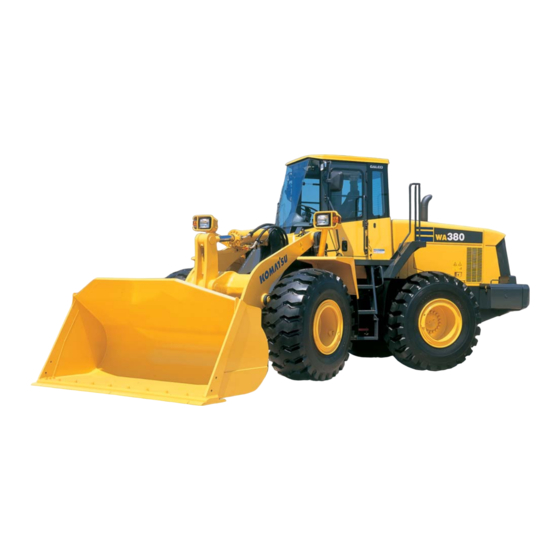
WHEEL LOADER
WA380
-5
60001
SERIAL NUMBERS
and up
WARNING
Unsafe use of this machine may cause serious injury or
death. Operators and maintenance personnel must read
this manual before operating or maintaining this machine.
This manual should be kept near the machine for
reference and periodically reviewed by all personnel who
will come into contact with it.
NOTICE
Komatsu has Operation & Maintenance Manuals
written in some other languages. If a foreign language
manual is necessary, contact your local distributor for
availability.
Advertisement
Chapters
Table of Contents

Subscribe to Our Youtube Channel
Related Manuals for Komatsu WA380-5


Summary of Contents for Komatsu WA380-5
- Page 1 This manual should be kept near the machine for reference and periodically reviewed by all personnel who will come into contact with it. NOTICE Komatsu has Operation & Maintenance Manuals written in some other languages. If a foreign language manual is necessary, contact your local distributor for availability.
- Page 2 1 - 1...
-
Page 3: Foreword
In case this manual should be lost or damaged, immediately contact Komatsu or your Komatsu distributor to obtain a new copy. When you sell the machine, make sure that this manual should be provided to the new owner together with the machine. -
Page 4: Safety Information
FOREWORD SAFETY INFORMATION SAFETY INFORMATION To enable you to use this machine safely, safety precautions and labels are given in this manual and affixed to the machine to give explanations of situations involving potential hazards and of the methods of avoiding such situations. - Page 5 Continuing improvements in the design of this machine can lead to changes in detail which may not be reflected in this manual. Consult Komatsu or your Komatsu distributor for the latest available information of your machine or for questions regarding information in this manual.
-
Page 6: Introduction
FOREWORD INTRODUCTION INTRODUCTION This Komatsu machine is designed to be used mainly for the following work: Digging work Smoothing Pushing work Loading work For details of the operating procedure, see "WORK POSSIBLE USING WHEEL LOADER (PAGE 3-127)". FRONT/REAR, LEFT/RIGHT DIRECTIONS OF MACHINE In this manual, the directions of the machine (front, rear, left, right) are determined according to the view from the operator's seat in the direction of travel (front) of the machine. -
Page 7: Necessary Information
FOREWORD NECESSARY INFORMATION NECESSARY INFORMATION When requesting service or ordering replacement parts, please inform your Komatsu distributor of the following items. PRODUCT IDENTIFICATION NUMBER (PIN)/MACHINE SERIAL NO. PLATE On the center right of the front frame. The design of the nameplate differs according to the territory. -
Page 8: Position Of Service Meter
FOREWORD NECESSARY INFORMATION POSITION OF SERVICE METER It is at the center bottom of the machine monitor. TABLE TO ENTER SERIAL NO. AND DISTRIBUTOR Machine serial No. Engine serial No. Product identification number (PIN) Distributor name Address Service Personnel Phone/Fax 1 - 7... -
Page 9: Table Of Contents
FOREWORD CONTENTS CONTENTS FOREWORD FOREWORD SAFETY INFORMATION INTRODUCTION FRONT/REAR, LEFT/RIGHT DIRECTIONS OF MACHINE NECESSARY INFORMATION PRODUCT IDENTIFICATION NUMBER (PIN)/MACHINE SERIAL NO. PLATE ENGINE SERIAL NO. PLATE POSITION OF SERVICE METER TABLE TO ENTER SERIAL NO. AND DISTRIBUTOR SAFETY SAFETY SAFETY LABELS LOCATION OF SAFETY LABELS SAFETY LABELS GENERAL PRECAUTIONS... - Page 10 RECOMMENDED FUEL, COOLANT, AND LUBRICANT USE OF FUEL, COOLANT AND LUBRICANTS ACCORDING TO AMBIENT TEMPERATURE 4- 10 RECOMMENDED BRANDS, RECOMMENDED QUALITY FOR PRODUCTS OTHER THAN KOMATSU GENUINE OIL 4- 11 STANDARD TIGHTENING TORQUES FOR BOLTS AND NUTS 4- 12 TORQUE LIST...
- Page 11 FOREWORD CONTENTS WHEN REQUIRED 4- 17 CHECK BEFORE STARTING 4- 41 EVERY 50 HOURS SERVICE 4- 42 EVERY 100 HOURS SERVICE 4- 43 EVERY 250 HOURS SERVICE 4- 45 EVERY 500 HOURS SERVICE 4- 51 EVERY 1000 HOURS SERVICE 4- 53 EVERY 2000 HOURS SERVICE 4- 56 EVERY 4000 HOURS SERVICE...
- Page 12 2 - 1...
-
Page 13: Safety
SAFETY SAFETY SAFETY SAFETY LABELS LOCATION OF SAFETY LABELS SAFETY LABELS GENERAL PRECAUTION SAFETY RULES 2- 11 IF ABNORMALITIES ARE FOUND 2- 11 CLOTHING AND PERSONAL PROTECTIVE ITEMS 2- 11 FIRE EXTINGUISHER AND FIRST AID KIT 2- 11 SAFETY FEATURES 2- 11 KEEP MACHINE CLEAN 2- 12... - Page 14 SAFETY SAFETY PRECAUTIONS FOR OPERATION 2- 20 STARTING ENGINE 2- 20 CHECKS BEFORE STARTING ENGINE 2- 20 PRECAUTIONS WHEN STARTING 2- 20 PRECAUTIONS IN COLD AREAS 2- 21 OPERATION 2- 22 CHECKS BEFORE OPERATION 2- 22 PRECAUTIONS WHEN TRAVELING IN FORWARD OR REVERSE 2- 22 PRECAUTIONS WHEN TRAVELING 2- 23...
- Page 15 SAFETY SAFETY PRECAUTIONS FOR MAINTENANCE 2- 32 WARNING TAG 2- 32 KEEP WORK PLACE CLEAN AND TIDY 2- 32 APPOINT LEADER WHEN WORKING WITH OTHERS 2- 32 STOP ENGINE BEFORE CARRYING OUT MAINTENANCE 2- 33 TWO WORKERS FOR MAINTENANCE WHEN ENGINE IS RUNNING 2- 34 INSPECTION AND MAINTENANCE AFTER TURNING E.C.S.S.
-
Page 16: Safety Labels
If the safety labels are damaged or lost, or cannot be read, replace them with new parts. For details of the part numbers, see this manual or check on the actual part, and order the new part from your Komatsu distributor. -
Page 17: Safety Labels
SAFETY SAFETY LABELS SAFETY LABELS (1) Caution before starting (09651-03001) (2) Caution for leaving the operator's seat (09654-03001) (3) Caution when traveling in reverse Please request part No. 421-93-23251 for this safety label. 2 - 6... - Page 18 SAFETY SAFETY SAFETY LABELS SAFETY LABELS (4) Caution for going close to electric cables (09801-13001) (5) Caution to keep away from movable parts (09162-23000) (6) Caution for frame lock bar (09161-23000) 2 - 7...
- Page 19 SAFETY SAFETY SAFETY LABELS SAFETY LABELS (7) Caution for parking brake (421-93-23351) (8) Warning for hot cooling water (09668-03001) (9) Caution when oil is at high temperature (09653-03001) (10) Caution when handling battery cable (09808-03000) 2 - 8...
- Page 20 SAFETY SAFETY SAFETY LABELS SAFETY LABELS (11) High pressure warning (09659-53000) (12) Do not climb on fender (09805-03000) (Machines with equipped with rear full fender) (13) "Do not open when engine is running" sign (09667-03001) (14) "Do not come near machine" sign (09812-13000) (15) "Do not go under work equipment"...
- Page 21 SAFETY SAFETY SAFETY LABELS SAFETY LABELS (16) "Do not modify ROPS" sign (09620-30201) (17) Prohibition of engine start by short-circuiting (09842-A0481) 2 - 10...
-
Page 22: General Precautions
SAFETY GENERAL PRECAUTIONS GENERAL PRECAUTIONS SAFETY RULES Only trained and authorized personnel can operate and maintain the machine. Follow all safety rules, precautions and instructions in this manual when operating or performing maintenance on the machine. If you are not feeling well, or if you are under the influence of alcohol or medication, your ability to safely operate or repair your machine may be severely impaired, putting yourself and everyone else on your job site in danger. -
Page 23: Keep Machine Clean
SAFETY GENERAL PRECAUTIONS KEEP MACHINE CLEAN If water gets into the electrical system, there is a hazard that it will cause malfunctions or misoperation. Do not use water or steam to wash the electrical system (sensors, connectors). If inspection and maintenance is carried out when the machine is still dirty with mud or oil, there is a hazard that you will slip and fall, or that dirt or mud will get into your eyes. -
Page 24: Handrails And Steps
SAFETY GENERAL PRECAUTIONS HANDRAILS AND STEPS To prevent personal injury caused by slipping or falling off the machine, always do as follows. Use the handrails and steps marked by arrows in the diagram on the right when getting on or off the machine. To ensure safety, always face the machine and maintain three-point contact (both feet and one hand, or both hands and one foot) with the handrails and steps to ensure that you support... -
Page 25: Mounting And Dismounting
SAFETY GENERAL PRECAUTIONS MOUNTING AND DISMOUNTING Never jump on or off the machine. Never get on or off a moving machine. If the machine starts to move when there is no operator on the machine, do not jump on to the machine and try to stop it. -
Page 26: Fire Prevention
SAFETY GENERAL PRECAUTIONS FIRE PREVENTION Fire caused by fuel or oil Fuel, oil, antifreeze, and window washer liquid are particularly flammable and can be hazardous. To prevent fire, always observe the following: Do not smoke or use any flame near fuel or oil. Stop the engine before refueling. -
Page 27: Action If Fire Occurs
Any modification made without authorization from Komatsu can create hazards. Before making a modification, consult your Komatsu distributor. Komatsu will not be responsible for any injuries, accidents, product failures or other property damages resulting from modifications made without authorization from Komatsu. -
Page 28: Safety At Worksite
SAFETY GENERAL PRECAUTIONS SAFETY AT WORKSITE Before starting operations, thoroughly check the area for any unusual conditions that could be dangerous. When carrying out operations near combustible materials such as thatched roofs, dry leaves or dry grass, there is a hazard of fire, so be careful when operating. Check the terrain and condition of the ground at the worksite, and determine the safest method of operation. -
Page 29: Do Not Go Close To High-Voltage Cables
SAFETY GENERAL PRECAUTIONS DO NOT GO CLOSE TO HIGH-VOLTAGE CABLES Do not travel or operate the machine near electric cables. There is a hazard of electric shock, which may cause serious personal injury or death. On jobsites where the machine may go close to electric cables, always do as follows. -
Page 30: Checking Signalman's Signals And Signs
Do not allow other persons to approach during the operation. Always observe the rules and regulations for the work site and environmental standards. This machine does not use asbestos, but there is a danger that imitation parts may contain asbestos, so always use genuine Komatsu parts. 2 - 19... -
Page 31: Precautions For Operation Starting Engine
SAFETY PRECAUTIONS FOR OPERATION PRECAUTIONS FOR OPERATION STARTING ENGINE If there is a warning tag hanging from the work equipment control lever, do not start the engine or touch the levers. CHECKS BEFORE STARTING ENGINE Carry out the following checks before starting the engine at the beginning of the day's work. Remove all dirt from the surface of the window glass to ensure a good view. -
Page 32: Precautions In Cold Areas
SAFETY PRECAUTIONS FOR OPERATION PRECAUTIONS IN COLD AREAS Carry out the warming-up operation thoroughly. If the machine is not thoroughly warmed up before the control levers are operated, the reaction of the machine will be slow, and this may lead to unexpected accidents. If the battery electrolyte is frozen, do not charge the battery or start the engine with a different power source. -
Page 33: Operation
SAFETY PRECAUTIONS FOR OPERATION OPERATION CHECKS BEFORE OPERATION When carrying out the checks, move the machine to a wide area where there are no obstructions, and operate slowly. Do not allow anyone near the machine. Always fasten your seat belt. Check the operation of travel, steering and brake systems, and work equipment control system. -
Page 34: Precautions When Traveling
This may cause the tires to burst. If a tire bursts, it produces an extremely large destructive force, and this may cause serious injury or accident. If you are going to travel continuously, please consult your Komatsu distributor. 2 - 23... -
Page 35: Traveling On Slopes
SAFETY PRECAUTIONS FOR OPERATION TRAVELING ON SLOPES To prevent the machine from tipping over or slipping to the side, always do as follows. When traveling on slopes, keep the work equipment height "A" at 20 to 30 cm (8 to 12 in) above the ground. In case of emergency, quickly lower the work equipment to the ground to help the machine to stop. -
Page 36: Prohibited Operations
SAFETY PRECAUTIONS FOR OPERATION PROHIBITED OPERATIONS It is dangerous to excavate the bottom of a rock face. Never do this. It is dangerous to use the bucket or lift arm for crane operations, so do not carry out such operations. Do not pass the bucket over the head of other workers or over the operator's seat of dump trucks or other hauling equipment. -
Page 37: Methods Of Using Brake
SAFETY SAFETY PRECAUTIONS FOR OPERATION PRECAUTIONS FOR OPERATION When handling unstable loads, such as round or cylindrical objects, or piled sheets, if the work equipment is raised high, there is danger that the load may fall on top of the operator' compartment and cause serious injury or damage. -
Page 38: Parking Machine
SAFETY PRECAUTIONS FOR OPERATION PARKING MACHINE Park the machine on firm, level ground. Select a place where there is no hazard of landslides, falling rocks, or flooding. Lower the work equipment completely to the ground. When leaving the machine, set work equipment lock lever (1) to the LOCK position and parking brake switch (2) to the ON position, and stop the engine. -
Page 39: Transportation
PRECAUTIONS FOR OPERATION TRANSPORTATION The machine can be divided into parts for transportation, so when transportating the machine, please contact your Komatsu distributor to have the work carried out. LOADING AND UNLOADING When loading or unloading the machine, mistaken operation may bring the hazard of the machine tipping over or falling, so particular care is necessary. -
Page 40: Battery
SAFETY PRECAUTIONS FOR OPERATION BATTERY BATTERY HAZARD PREVENTION Battery electrolyte contains sulphuric acid, and batteries generate flammable hydrogen gas, which may explode. Mistaken handling can lead to serious injury or fire. For this reason, always observe the following precautions. Do not use or charge the battery if the battery electrolyte level is below the LOWER LEVEL line. This may cause an explosion. -
Page 41: Starting With Booster Cables
SAFETY PRECAUTIONS FOR OPERATION STARTING WITH BOOSTER CABLES If any mistake is made in the method of connecting the booster cables, it may cause the battery to explode, so always do as follows. When starting with a booster cable, carry out the starting operation with two workers (one worker sitting in the operator's seat and the other working with the battery). -
Page 42: Towing
SAFETY PRECAUTIONS FOR OPERATION TOWING WHEN TOWING Serious injury or death could result if there is any mistake in the selection of wire rope or method of towing a disabled machine. For details of the procedure for towing, see the "METHOD OF TOWING MACHINE (PAGE 3-153)" Always be sure to check carefully that the capacity of the wire rope used for towing is ample for the weight of the towed machine. -
Page 43: Precautions For Maintenance
SAFETY PRECAUTIONS FOR MAINTENANCE PRECAUTIONS FOR MAINTENANCE WARNING TAG Always attach the "DO NOT OPERATE" warning tag to the work equipment control lever in the operator's cab to alert others that you are performing service or maintenance on the machine. Attach additional warning tags around the machine if necessary. -
Page 44: Stop Engine Before Carrying Out Maintenance
SAFETY PRECAUTIONS FOR MAINTENANCE STOP ENGINE BEFORE CARRYING OUT MAINTENANCE Stop the machine on firm, level ground. Select a place where there is no hazard of landslides, falling rocks, or flooding. Lower the work equipment completely to the ground and stop the engine. -
Page 45: Two Workers For Maintenance When Engine Is Running
SAFETY SAFETY PRECAUTIONS FOR MAINTENANCE PRECAUTIONS FOR MAINTENANCE Lock the front and rear frames with frame lock bar (4). TWO WORKERS FOR MAINTENANCE WHEN ENGINE IS RUNNING To prevent personal injury, do not carry out maintenance with the engine running. If maintenance must be carried out with the engine running, carry out the operation with at least two workers and do as follows. -
Page 46: Proper Tools
Do not make holes in it, weld it, or use a cutting torch. Do not hit or roll the accumulator, or subject it to any impact. When disposing of the accumulator, the gas must be released. Please contact your Komatsu distributor to have this work performed. PERSONNEL Do not allow any unauthorized personnel into the area when servicing the machine. -
Page 47: Work Under The Machine
SAFETY PRECAUTIONS FOR MAINTENANCE WORK UNDER THE MACHINE When carrying out inspection and maintenance with the work equipment raised, use strong support (1) that can fully withstand the weight of the work equipment, and be sure to fix the stands in position securely. -
Page 48: Precautions With High-Pressure Oil
If any loose bolts are found, stop work and tighten to the specified torque. If any damaged hoses are found, stop operations immediately and contact your Komatsu distributor. Replace the hose if any of the following problems are found. -
Page 49: Compressed Air
SAFETY PRECAUTIONS FOR MAINTENANCE COMPRESSED AIR When carrying out cleaning with compressed air, there is a hazard of serious injury caused by flying particles. When using compressed air to clean elements or the radiator, always wear safety glasses, dust mask, gloves, and other protective equipment. -
Page 50: Precautions With Tires
Komatsu distributor to carry out these operations. Always use the tires specified by Komatsu and maintain the specified inflation pressure. Suitable tire inflation pressure: see "HANDLING THE TIRES (PAGE 3-140)"... - Page 52 3 - 1...
-
Page 53: General View
OPERATION GENERAL VIEW GENERAL VIEW GENERAL VIEW OF MACHINE Bucket Turn signal lamp Bell crank Head lamp Front wheel (10) Lift cylinder Bucket cylinder (11) Lift arm Front working lamp (12) Rear working lamp ROPS cab (13) Rear combination lamp Rear wheel 3 - 2... -
Page 54: General View Of Controls And Gauges
OPERATION GENERAL VIEW GENERAL VIEW OF CONTROLS AND GAUGES Gearshift lever stopper (13) Dimmer switch Rear wiper switch (14) Parking brake switch Front wiper switch (15) Cigarette lighter Gearshift lever (16) Load meter cancel switch (if equipped) Front switch panel (17) Kickdown switch Directional lever... - Page 55 OPERATION GENERAL VIEW MACHINE MONITOR Central warning lamp (21) Auto-greasing pilot lamp (if equipped) Brake oil pressure caution lamp (22) Joystick pilot lamp (if equipped) Engine oil pressure caution lamp (23) Directional selector pilot lamp (if equipped) Brake oil level caution lamp (24) Shift indicator Radiator coolant level caution lamp...
- Page 56 OPERATION GENERAL VIEW SWITCH PANEL RIGHT SWITCH PANEL FRONT SWITCH PANEL Transmission shift mode selector switch (14) Monitor panel mode selector switch 1 Transmission cut-off set switch (15) Monitor panel mode selector switch 2 Cooling fan reverse rotation switch (16) Front working lamp switch Emergency steering switch (17)
-
Page 57: Explanation Of Components
The indicator gauges and meters are actuated after the above system check is completed. The character display shows "KOMATSU SYSTEM CHECK" for 3 seconds. If the lamps do not light up, there is probably a failure or disconnection, so contact your Komatsu distributor for inspection. 3 - 6... - Page 58 OPERATION EXPLANATION OF COMPONENTS TYPES OF WARNING If an abnormality occurs on the machine, or if any switch or lever is operated accidently, the monitor display and buzzer give a warning to inform the operator. Following are the types of warning depending on the level of danger.
- Page 59 When the starting switch is at the OFF position, if the service meter is displayed even though the top ( ) of monitor panel mode selector switch 1 is not being pressed, there is probably a failure in the machine, so please contact your Komatsu distributor for inspection.
- Page 60 If action code E03 is displayed, stop the machine immediately and check the failure code. For details, see "FAILURE CODE DISPLAY (PAGE 3-11)". Inform your Komatsu distributor of the failure code and ask for repairs. If there is a failure on the machine, or it is necessary to change the method of operation, or if inspection or maintenance must be carried out, action code E00, E01, E02, or E03 is displayed on the character display in display portion (3).
- Page 61 E02: If this code is displayed, stop the machine and run the engine under no load at a mid-range speed. If an action code is still displayed after taking the necessary action, check the failure code and contact your Komatsu distributor for repairs. REMARK The top line of the character display displays "E02"...
- Page 62 If an action code is displayed on the character display, check the failure code according to the failure code display method given below. When contacting your Komatsu distributor to request repairs, inform your distributor of the failure code. Method of displaying failure code 1.
- Page 63 OPERATION EXPLANATION OF COMPONENTS FILTER, OIL REPLACEMENT TIME DISPLAY After completion of the system check and when the starting switch is in the ON position, if any filter or oil item is approaching the replacement time, this display (5) shows the item for approx. 30 seconds.
- Page 64 OPERATION EXPLANATION OF COMPONENTS REMARK See the section below for details of the procedure for replacing the filter and oil. Engine oil "CHANGE OIL IN ENGINE OIL PAN, REPLACE ENGINE OIL FILTER CARTRIDGE (PAGE 4-51)" Engine oil filter "CHANGE OIL IN ENGINE OIL PAN, REPLACE ENGINE OIL FILTER CARTRIDGE (PAGE 4-51)" Fuel filter "REPLACE FUEL FILTER CARTRIDGE (PAGE 4-52)"...
- Page 65 OPERATION EXPLANATION OF COMPONENTS EMERGENCY STOP ITEMS CAUTION If these lamps light up and the buzzer sounds, stop operations immediately and carry out inspection and maintenance of the applicable location. If any abnormality is found in the emergency stop items, the alarm buzzer will sound intermittently, and the lamp for the location of the abnormality and the central warning lamp will light up.
- Page 66 OPERATION EXPLANATION OF COMPONENTS During operation (engine running) If the brake oil pressure goes down during operation, the brake oil pressure caution lamp and central warning lamp light up and the alarm buzzer sounds intermittently. At the same time, the top line of the character display displays "E03" and the bottom line displays "CHECK RIGHT NOW"...
- Page 67 OPERATION EXPLANATION OF COMPONENTS STEERING OIL PRESSURE CAUTION LAMP (Red) This lamp (4) lights up to warn the operator that the steering oil pressure has dropped. During checks before starting (when the starting switch is turned to the ON position but the engine is not started), this monitor does not light up.
- Page 68 OPERATION EXPLANATION OF COMPONENTS CAUTION ITEMS CAUTION If these lamps light up, stop operations quickly and carry out the following action. Axle oil temperature caution lamp Hydraulic oil temperature caution lamp Torque converter oil temperature caution lamp Fuel level caution lamp Engine coolant temperature caution lamp AXLE OIL TEMPERATURE CAUTION LAMP This lamp (1) lights up to warn the operator that the brake oil...
- Page 69 OPERATION EXPLANATION OF COMPONENTS TORQUE CONVERTER OIL TEMPERATURE CAUTION LAMP This lamp (2) lights up to warn the operator that the torque converter oil temperature has risen. During checks before starting (when the starting switch is turned to the ON position but the engine is not started), this monitor does not light up.
- Page 70 OPERATION EXPLANATION OF COMPONENTS HYDRAULIC OIL TEMPERATURE CAUTION LAMP This lamp (4) lights up to warn the operator that the hydraulic oil temperature has risen. During checks before starting (when the starting switch is turned to the ON position but the engine is not started), this monitor does not light up.
- Page 71 OPERATION EXPLANATION OF COMPONENTS INSPECTION AND MAINTENANCE ITEMS CAUTION If these lamps light up, stop operations quickly and carry out the following action. Radiator coolant level caution lamp Air cleaner clogging caution lamp Engine oil level caution lamp Brake oil level caution lamp Battery electrolyte level caution lamp (if equipped) Transmission oil filter clogging caution lamp Maintenance caution lamp...
- Page 72 OPERATION EXPLANATION OF COMPONENTS ENGINE OIL LEVEL CAUTION LAMP This lamp (2) lights up to warn the operator that the oil level in the engine oil pan has gone down. During checks before starting (when the starting switch is turned to the ON position but the engine is not started), this monitor lights up if the oil level in the engine oil pan is low.
- Page 73 OPERATION EXPLANATION OF COMPONENTS MAINTENANCE CAUTION LAMP CAUTION If the caution lamp lights up, repair the problem as soon as possible. If this is left as it is, it will lead to failure. When the time for oil change is reached, this lamp (4) flashes or lights up for approx.
- Page 74 OPERATION EXPLANATION OF COMPONENTS BRAKE OIL LEVEL CAUTION LAMP This lamp (6) is not used. On this machine, the hydraulic oil is used for the brake oil. TRANSMISSION OIL FILTER CLOGGING CAUTION LAMP This lamp (7) is not used. 3 - 23...
- Page 75 OPERATION EXPLANATION OF COMPONENTS PILOT DISPLAY PORTION When the starting switch is ON, the pilot display lights up when the display items are functioning. Parking brake pilot lamp Directional selector pilot lamp (if equipped) Cooling fan reverse rotation pilot lamp (10) Shift indicator Emergency steering pilot lamp...
- Page 76 OPERATION EXPLANATION OF COMPONENTS COOLING FAN REVERSE ROTATION PILOT LAMP This lamp (2) lights up when the direction of rotation of the cooling fan is reversed. At the same time, "COOLING FAN REVERSE" is displayed on the character display. REMARK When the engine is running, even if the cooling fan reverse switch is operated, the fan does not rotate in reverse.
- Page 77 OPERATION EXPLANATION OF COMPONENTS PREHEATING PILOT LAMP This lamp (5) lights up when the engine preheating electric heater is actuated. In cold weather, when the starting switch is turned to the ON position, this lamp lights up. When the preheating is completed, it goes out.
- Page 78 OPERATION EXPLANATION OF COMPONENTS SHIFT INDICATOR This indicator (10) indicates the transmission gear range (actual travel speed range). AUTO-SHIFT PILOT LAMP This lamp (11) lights up when the auto-shift function is selected. Use the transmission shift mode selector switch to select the shift mode.
- Page 79 OPERATION EXPLANATION OF COMPONENTS SHIFT LEVER POSITION PILOT LAMP This lamp (14) displays the transmission position of the gearshift lever. TURN SIGNAL PILOT LAMP This lamp (15) flashes at the same time as the turn signal lamp flashes. REMARK If there is a disconnection in the turn signal lamp, the flashing interval becomes shorter.
- Page 80 OPERATION EXPLANATION OF COMPONENTS METER DISPLAY PORTION Torque converter oil temperature gauge Fuel gauge Engine coolant temperature gauge Speedometer Hydraulic oil temperature gauge Meter display pilot lamp TORQUE CONVERTER OIL TEMPERATURE GAUGE This meter (1) indicates the torque converter oil temperature. It should be in white range (A) during operations.
- Page 81 It is also possible to display the engine speed by switching meter (5). If you wish to switch between the speedometer and tachometer, please contact your Komatsu distributor to have it switched. METER DISPLAY PILOT LAMP This lamp (6) displays the unit for the travel speed or engine tachometer.
- Page 82 OPERATION EXPLANATION OF COMPONENTS OTHER FUNCTIONS OF MACHINE MONITOR The machine monitor also has the following functions. Odometer, filter/oil replacement time reset, telephone number input, language selection, monitor brightness adjustment METHOD OF DISPLAYING ODOMETER Use this when checking the total distance that the machine has traveled. 1.
- Page 83 OPERATION EXPLANATION OF COMPONENTS RESET METHOD FOR FILTER, OIL REPLACEMENT TIME The filter and oil replacement time is displayed on the character display, so if the filter and oil have been replaced, reset the filter and oil change time. 1. Press the ( ) of monitor panel mode selector switch 1, and display the odometer. 2.
- Page 84 OPERATION EXPLANATION OF COMPONENTS INPUT METHOD FOR TELEPHONE NUMBER It is possible to display the telephone number on the right side of "CALL" displayed on the character display when action code "E03" is generated. 1. Press the ( ) of monitor panel mode selector switch 1, and display the odometer. 2.
- Page 85 OPERATION EXPLANATION OF COMPONENTS METHOD FOR SELECTING LANGUAGE Use this when switching the language displayed on the character display. The following explanation is for when English is set as the language for the character display. 1. Press the ( ) of monitor panel mode selector switch 1, and display the odometer. 2.
- Page 86 OPERATION EXPLANATION OF COMPONENTS METHOD OF ADJUSTING MONITOR BRIGHTNESS Do as follows to adjust the brightness of the monitor. 1. Press the ( ) of monitor panel mode selector switch 1, and display the odometer. 2. Press (>) or (<) of monitor panel mode selector switch 2 and display "BRIGHTNESS ADJUST".
-
Page 87: Switches
OPERATION EXPLANATION OF COMPONENTS SWITCHES 3 - 36... - Page 88 OPERATION OPERATION EXPLANATION OF COMPONENTS EXPLANATION OF COMPONENTS Starting switch (19) Room lamp switch Power mode selector switch (20) Rear heated wire glass switch Transmission shift mode selector switch (21) E.C.S.S. Transmission cut-off switch (electronic controlled suspension system) Transmission cut-off set switch switch (if equipped) Lamp switch (22)
- Page 89 OPERATION EXPLANATION OF COMPONENTS MANUAL position When starting in cold weather, set to this position if it is desired to extend the preheating time beyond the automatic preheating time. When the switch is released, it will return to the OFF position, so turn it immediately to the START position and start the engine.
- Page 90 OPERATION EXPLANATION OF COMPONENTS TRANSMISSION CUT-OFF SWITCH WARNING When moving the machine off on an uphill slope, set the transmission cut-off switch to the OFF position, depress the accelerator pedal while keeping the left brake pedal depressed, then gradually release the brake pedal and allow the machine to move. In this way the machine can be prevented from traveling backwards.
- Page 91 OPERATION EXPLANATION OF COMPONENTS LAMP SWITCH This switch (6) is used to light up the front lamps, side clearance lamps, tail lamps, and instrument panel. Position (a): OFF Position (b): Side clearance lamps, tail lamps, and instrument panel light up Position (c): Head lamps light up in addition to lamps at (b) position REMARK The lamp switch can be operated regardless of the position of the...
- Page 92 Stop the machine first, then apply the parking brake. If the parking brake has to be used as an emergency brake when the machine is traveling at high speed, ask your Komatsu distributor to carry out inspection to check that there is no damage to the parking brake.
- Page 93 OPERATION EXPLANATION OF COMPONENTS FRONT WORKING LAMP SWITCH WARNING Always turn the working lamp off before traveling on public roads. When turning the front working lamp ON, operate the lamp switch to turn the side clearance lamp ON or the head lamp ON, then operate this switch (10).
- Page 94 OPERATION EXPLANATION OF COMPONENTS MONITOR PANEL MODE SELECTOR SWITCH 2 This switch (13) is used to switch the function of the character display. When the switch is released, it automatically returns to its original position. The basic operation is as follows. Position (>): Press here to go on to the next screen, or to move the cursor forward, or to increase the number when entering numerals...
- Page 95 OPERATION EXPLANATION OF COMPONENTS HOLD SWITCH To fix the speed range when traveling in automatic transmission, press switch (15) at the side of the lift arm control lever knob. The transmission will be fixed in the speed range displayed on shift indicator (A) on the machine monitor and shift hold pilot lamp (B) will light up.
- Page 96 OPERATION EXPLANATION OF COMPONENTS CIGARETTE LIGHTER This is used to light cigarettes. After cigarette lighter (18) is pushed in, it will return to its original position after a few seconds, so pull it out and light your cigarette. ROOM LAMP SWITCH The switch (19) is used to turn the room lamp ON and OFF.
- Page 97 OPERATION EXPLANATION OF COMPONENTS E.C.S.S. (ELECTRONIC CONTROLLED SUSPENSION SYSTEM) SWITCH (If equipped) WARNING If the machine is traveling or the work equipment is raised, the moment the E.C.S.S. switch is turned ON, the work equipment will move. If operations are carried out with the E.C.S.S. switch at the ON position, the moment the E.C.S.S. switch is operated, the work equipment may move.
- Page 98 OPERATION EXPLANATION OF COMPONENTS EMERGENCY STEERING SWITCH (If equipped) This switch (22) is the manual control switch for the emergency steering. Even when the engine has stopped, steering operations are made possible by pressing this switch. Position (a): ON The pilot lamp inside the switch and the emergency steering pilot lamp on the machine monitor light up and it becomes possible to operate the steering.
- Page 99 OPERATION EXPLANATION OF COMPONENTS DIRECTIONAL SELECTOR SWITCH (If equipped) This switch (24) is used to switch the direction of travel of the machine between forward and reverse. F Position: FORWARD N Position: Neutral R Position: REVERSE Before operating this switch, check that the condition is as follows. Directional lever is at N Directional selector switch actuation switch is at ON If the condition is not as above, the switch will not work.
- Page 100 OPERATION EXPLANATION OF COMPONENTS AFTERCOOLER TILT SWITCH (If equipped) This switch (30) can be used to tilt the aftercooler electrically. Use this when cleaning the cooler fins. Position (a): Cooler is tilted 17 degrees Position (b): Cooler is returned to original position TORQUE CONVERTER LOCK-UP SWITCH (If equipped) For details of the torque converter lock-up, see "HANDLING TORQUE CONVERTER LOCK-UP (PAGE 6-28)"...
-
Page 101: Control Levers, Pedals
OPERATION EXPLANATION OF COMPONENTS CONTROL LEVERS, PEDALS Gearshift lever Bucket control lever Directional lever Lift arm control lever Gearshift lever stopper Brake pedal Work equipment lock lever Accelerator pedal GEARSHIFT LEVER This lever (1) changes the speed range of the transmission. MANUAL SHIFT This machine has a 4-FORWARD, 4-REVERSE speed transmission. - Page 102 OPERATION OPERATION EXPLANATION OF COMPONENTS EXPLANATION OF COMPONENTS REMARK The length of the lever can be adjusted to 3 stages (positions (A), (B), (C)). To adjust the length, remove the screw at the bottom of the lever knob, slide the knob to the desired position, then tighten the screw again.
- Page 103 OPERATION OPERATION EXPLANATION OF COMPONENTS EXPLANATION OF COMPONENTS To set to the desired speed range when traveling uphill or downhill, or when carrying out grading, do as follows. When fixing the speed range Press the HOLD switch on the lift arm control lever. The speed range is fixed at the speed range displayed on the transmission indicator on the main monitor.
- Page 104 OPERATION EXPLANATION OF COMPONENTS WORK EQUIPMENT LOCK LEVER WARNING Before standing up from the operator's seat, set the work equipment lock lever securely to the LOCK position. If the work equipment lock lever is not at the LOCK position, and work equipment control lever (A) is touched by mistake, it may lead to a serious accident.
- Page 105 OPERATION EXPLANATION OF COMPONENTS LIFT ARM CONTROL LEVER This lever (6) is used to operate the lift arm. NOTICE Do not use the FLOAT position when lowering the bucket. Use the FLOAT position when leveling, see "LEVELING OPERATIONS (PAGE 3-130)". Position (a): RAISE When the lift arm control lever is pulled further from the RAISE position, the lever is stopped in this...
-
Page 106: Steering Tilt Lock Lever
Do not operate the lever (1) continuously by excessive force. The lever (1) may become loose or get out of angle. In this case, please ask your Komatsu distributor to carry out repairs. The bolts (2) and (3) on steering column are the left-hand screw. -
Page 107: Cap With Lock
OPERATION EXPLANATION OF COMPONENTS CAP WITH LOCK The fuel tank filler port and the hydraulic tank filler port (if equipped) are equipped with locks. Use the starting switch key to open and close the cap. METHOD OF OPENING AND CLOSING CAP WITH LOCK (FOR THE FUEL TANK FILLER PORT) TO OPEN THE CAP 1. - Page 108 OPERATION EXPLANATION OF COMPONENTS METHOD OF OPENING AND CLOSING CAP WITH LOCK (FOR THE HYDRAULIC TANK FILLER PORT) (If equipped) TO OPEN THE CAP 1. Insert the starting switch key into the cap as far as it will go (to the shoulder).
-
Page 109: Frame Lock Bar
OPERATION EXPLANATION OF COMPONENTS FRAME LOCK BAR WARNING When carrying out maintenance or transporting the machine, always set the frame lock bar to the LOCK position. Always remove the frame lock bar for travel operations. If it is not removed, the steering wheel cannot be used for steering, and this may lead to serious damage or injury. -
Page 110: Grease Pump
OPERATION EXPLANATION OF COMPONENTS GREASE PUMP The grease pump is stored inside the battery box at the rear of the machine. After using it, wipe off all grease stuck to the outside of the pump and then store it in the box. It can be stored in either the left or right battery box. -
Page 111: Fuse
OPERATION EXPLANATION OF COMPONENTS FUSE NOTICE Before replacing a fuse, be sure to turn off the starting switch. The fuses protect the electrical equipment and wiring from burning out. If the fuse becomes corroded, or white powder can be seen, or the fuse is loose in the fuse holder, replace the fuse. -
Page 112: Slow Blow Fuse
OPERATION EXPLANATION OF COMPONENTS FUSE BOX B Fuse Name of circuit capacity Starting switch Hazard lamp Instrument panel A Room lamp Spare 1 Power mode selector motor Turn signal indicator Front working lamp Rear working lamp (10) Instrument panel B (11) Car radio (12) -
Page 113: Power Outlet
OPERATION EXPLANATION OF COMPONENTS POWER OUTLET NOTICE There are two power sources: 12V and 24V Check the voltage of the electrical equipment and select the appropriate power source. Mistaken use, such as using 24V as the power source for 12V equipment, will cause failure of the equipment. When using the electric power source, do not install any equipment which will exceed the maximum amperage. -
Page 114: Am/Fm Radio
OPERATION EXPLANATION OF COMPONENTS AM/FM RADIO (Machine equipped with cab) (If equipped) EXPLANATION OF COMPONENTS Power switch/Volume Preset switch Tone control knob Seek Display Band selector switch Clock button/Displaying frequency Tuning switch POWER SWITCH/VOLUME When this switch (1) is turned to the right, it clicks and the power is turned on. - Page 115 OPERATION EXPLANATION OF COMPONENTS TONE CONTROL KNOB If this knob (2) is turned to the right, the high tone is emphasized; if it is turned to the left, the high tone is reduced. DISPLAY This display (3) shows the radio reception frequency and the operating mode.
- Page 116 OPERATION EXPLANATION OF COMPONENTS PRESET SWITCH With this switch (6), each button can be preset to one station each for FM and MW (AM). (For details of the method of presetting, see Section "METHOD OF PRESETTING STATION (PAGE 3-67)".) SEEK When this switch (7) ("SEEK") is pressed, it automatically searches for stations that can be received, and when it receives a station, it stops.
- Page 117 OPERATION EXPLANATION OF COMPONENTS METHOD OF OPERATION LISTENING TO RADIO 1. Turn radio power switch (1) ON. 2. "BAND" switch (2) is used to select MW (AM) or FM. 3. Use the preset switch or tuning switch (3) to select the station. 4.
- Page 118 OPERATION EXPLANATION OF COMPONENTS METHOD OF PRESETTING STATION 1. Select the desired preset station. Use the "BAND" button to select MW (AM) or FM, and use the "TUNE" button to select the frequency of the broadcasting station. 2. Decide the number of the button to be preset, and keep it pressed for 2 seconds.
- Page 119 OPERATION EXPLANATION OF COMPONENTS METHOD OF SETTING TIME 1. Turn the starting switch ON, then turn radio power source (1) ON. If the display is showing the frequency, press the CLOCK button to display the time. 2. To set the time, keep the CLOCK button pressed and Press the button to change the minutes Press the...
-
Page 120: Am/Fm Radio-Cassette Stereo
OPERATION EXPLANATION OF COMPONENTS AM/FM RADIO-CASSETTE STEREO (Machine equipped with cab) (If equipped) EXPLANATION OF COMPONENTS Power switch/volume Cassette door Auto-store/preset scan button Fast forward, rewind buttons Bass control knob (10) Preset buttons Treble control knob (11) Metal tape button Loudness button (12) Manual tuning buttons... - Page 121 OPERATION EXPLANATION OF COMPONENTS POWER SWITCH/VOLUME Turn this knob (1) to the right until it clicks to turn the power on. Turn it further to increase the volume. AUTO-STORE/PRESET SCAN BUTTON Use this button (2) to actuate the preset scan and auto-store functions.
- Page 122 OPERATION EXPLANATION OF COMPONENTS TREBLE CONTROL KNOB Turn this button (4) to the left to reduce the low tones; turn it to the right to emphasize the high tones. Direction (a): High tone reduced Direction (b): High tone emphasized LOUDNESS BUTTON This button (5) is used when playing at low volume.
- Page 123 OPERATION EXPLANATION OF COMPONENTS TAPE EJECT BUTTON This button (7) is used to stop the tape and to eject the cassette. When this button is pressed, the tape is ejected and the radio plays. CASSETTE DOOR Set the cassette with the exposed portion of the tape on the right side and insert it through the cassette door (8).
- Page 124 OPERATION EXPLANATION OF COMPONENTS METAL TAPE BUTTON (used also for preset button No. 5) This button (11) is used when playing a metal or chrome tape. This button is also used for preset button No. 5. When it is pressed, "MTL"...
- Page 125 OPERATION EXPLANATION OF COMPONENTS METHOD OF OPERATION METHOD OF SETTING PRESET BUTTONS It is possible to preset 6 MW (AM) stations and 12 FM stations (FM1: 6 stations, FM2: 6 stations). REMARK If you are playing the cassette, press the tape eject button to stop the tape. METHOD OF AUTO PRESET 1.
- Page 126 OPERATION EXPLANATION OF COMPONENTS LISTENING TO RADIO 1. Turn the starting switch ON, then turn power switch (1) ON. 2. Use band selector button (2) to select MW (AM), FM1 or FM2. 3. Select the station with the preset buttons (3). REMARK In case you do not promptly remember the number assigned to a certain preset station, press auto-store/preset scan button (4) for...
- Page 127 If the sound cannot be heard, nothing is displayed, or any other problem occurs, turn off the power switch and ask your Komatsu distributor to make repairs without delay. Stow the antenna when traveling in places with low overhead clearance.
-
Page 128: Air Conditioner
OPERATION EXPLANATION OF COMPONENTS AIR CONDITIONER (Machine equipped with cab) (If equipped) By taking fresh air into the cab through a filter, it is possible to raise the pressure inside the cab. This makes it possible to provide a pleasant working environment even on dusty jobsites. GENERAL LOCATIONS AND FUNCTION OF CONTROL PANEL Fan switch FRESH/RECIRC selector switch... - Page 129 OPERATION EXPLANATION OF COMPONENTS AIR CONDITIONER SWITCH This switch (2) is used to start or stop the cooling or dehumidifying function. When the fan switch is turned ON and the air conditioner switch is pressed, the indicator lamp above the switch lights up. When the switch is pressed again, the switch is turned OFF and the indicator lamp goes out.
- Page 130 OPERATION EXPLANATION OF COMPONENTS TEMPERATURE CONTROL SWITCH The temperature can be adjusted with this switch (5) by pressing and holding the up or down button. The temperature level indicator lamps light up to display the temperature of the air coming from the vents. The more the blue lamps light up, the lower the temperature is.
- Page 131 OPERATION EXPLANATION OF COMPONENTS METHOD OF OPERATION Switch Air conditioner Temperature FRESH/RECIRC Mode selector Fan switch switch control switch selector switch switch Condition of use Rapid All blue RECIRC FACE Cooling More than half Normal HI - LO FRESH FACE are blue Dehumidifying, More than half...
- Page 132 OPERATION EXPLANATION OF COMPONENTS COOL BOX When the cooling is being used, this can be used for keeping drinks and other things cool. When the heating is being used, it can be used to keep things warm. When using the box, open the vent grill. When not using the box, close the grill.
-
Page 133: Handling Auto Air Conditioner
OPERATION EXPLANATION OF COMPONENTS HANDLING AUTO AIR CONDITIONER (Machine equipped with cab) (If equipped) By taking fresh air into the cab through a filter, it is possible to raise the pressure inside the cab. This makes it possible to provide a pleasant working environment even on dusty jobsites. NAMES AND FUNCTIONS OF ITEMS ON CONTROL PANEL OFF switch Auto switch... - Page 134 OPERATION EXPLANATION OF COMPONENTS FAN SWITCH Switch (2) is used to adjust the air flow. The air flow can be adjusted to six levels. Press the ∧ switch to increase the air flow; press the ∨ switch to reduce the air flow. When the fan switch is pressed, the lamp at the top of the auto switch goes out.
- Page 135 OPERATION EXPLANATION OF COMPONENTS MODE SELECTOR SWITCH Switch (4) is used to select the vents. The vent position can be selected from five modes: FACE, FACE/FOOT, FOOT, FOOT/DEF, DEF. When this switch (4) is pressed, the display on monitor panel (7) changes in turn, and the air blows out from the vents shown in the display.
- Page 136 OPERATION EXPLANATION OF COMPONENTS MONITOR PANEL The monitor panel shows the temperature setting (a), air flow (b), and vent selection (c). AIR CONDITIONER SWITCH Switch (8) is used to turn the air conditioner (cooling, dehumidifying, heating) ON or OFF. When the auto switch or fan switch is turned ON and air conditioner switch (8) is pressed, the air conditioner is switched ON, the lamp at the top of the air conditioner switch lights up, and the air conditioner starts.
- Page 137 OPERATION EXPLANATION OF COMPONENTS CONTROL METHOD The air conditioner can be operated automatically or manually. Select the method of operation as desired. AUTOMATIC WARMING-UP 1. Turn auto switch (5) ON. The lamp above switch (5) lights up. The set temperature (a) and air flow (b) are displayed on the monitor.
- Page 138 OPERATION EXPLANATION OF COMPONENTS MANUAL OPERATION 1. Press fan switch (2) and select the air flow. Check that the set temperature (a) and air flow (b) are displayed on the monitor panel. 2. Turn air conditioner switch (8) ON. Check that the lamp above air conditioner switch lights up.
- Page 139 OPERATION OPERATION EXPLANATION OF COMPONENTS EXPLANATION OF COMPONENTS 4. Press mode selector switch (4) and select the desired vent. The display of the vent selection (c) on the monitor panel will change according to the selection. 5. Press RECIRC/FRESH selector switch (6) and select recirculation of the air inside the cab (RECIRC) or intake of fresh air from outside (FRESH).
-
Page 140: Handling Cab Wiper
OPERATION EXPLANATION OF COMPONENTS HANDLING CAB WIPER PREVENTING DAMAGE TO WIPER ARM BRACKET NOTICE When angling the wiper arm to the front, check that the wiper blade is hanging free. When angling the wiper arm to the front, such as when wiping the glass clean, if the wiper arm is angled with the wiper blade locked to the arm (the bottom of the blade is caught on the arm), abnormal force is brought to bear on the mounting bracket and the bracket... -
Page 141: Operation
Remove any flammable materials from around the battery, engine, muffler, turbocharger, or other high temperature engine parts. Leakage of fuel or oil will cause the machine to catch fire. Check carefully, be sure to repair any problem, or contact your Komatsu distributor. - Page 142 OPERATION OPERATION 9. Check for loose air cleaner mounting bolts. Check for the loose bolts. If loose, tighten them. 10. Check for loose battery terminals. Tighten any loose terminal. 11. Check for damage to the seat belt and mounting clamps. WARNING Even if there appears to be no abnormality with the seat belt, replace it once every three years.
- Page 143 OPERATION OPERATION 13. Inspect tires. WARNING If worn or damaged tires are used, they may burst and cause serious injury or death. To ensure safety, do not use the following tires. Wear: Tires with a tread grooves of less than 15% of that of a new tire Tires with extreme uneven wear or with stepped-type wear Damage: Tires with damage that has reached the cords, or with cracks in the...
- Page 144 2. Check that all the monitors, gauges, and the central warning lamp light up for approx. 3 seconds and the alarm buzzer sounds for approx. 1 sec. If the lamps do not light up, there is probably a failure or disconnection. Contact your Komatsu distributor inspection. 3 - 93...
- Page 145 OPERATION OPERATION CHECK COOLANT LEVEL, ADD COOLANT WARNING Do not open the radiator cap unless necessary. When checking the coolant, always wait for the engine to cool down and check the sub tank. Immediately after the engine is stopped, the coolant is at a high temperature and the radiator is under high internal pressure. If the cap is removed to check the coolant level in this condition, there is a hazard of burns.
- Page 146 OPERATION OPERATION CHECK OIL LEVEL IN ENGINE OIL PAN, ADD OIL WARNING Parts and oil are at high temperature immediately after the engine is stopped and may cause serious burns. Wait for the oil temperature to go down before performing this operation. 1.
- Page 147 OPERATION OPERATION CHECK FUEL LEVEL, ADD FUEL WARNING When filling with fuel, do not add any more fuel after the fuel supply has automatically stopped. If too much fuel is added, there is danger that the fuel may expand because of the rise in the ambient temperature and cause the fuel to overflow. Spilled fuel may cause fire, so always wipe off any spilled fuel completely.
- Page 148 CHECK BRAKE PEDAL Drive the machine forward and check the effect of the brakes. If there is any problem in the actuation of the brakes, please contact your Komatsu distributor to have the brakes adjusted. CHECK INFLATION PRESSURE OF TIRES Measure the inflation pressure with a tire pressure gauge, while the tires are cool, before starting work.
- Page 149 OPERATION OPERATION ADJUSTMENT SEAT ADJUSTMENT WARNING When adjusting the position of the operator's seat, always set the work equipment lock lever to the LOCK position to prevent any accidental contact with the control levers. Always adjust the operator's seat before starting each operation or when the operators change shift. When adjusting the seat, put your back against the backrest and adjust to a position where the brake pedal can be fully depressed.
- Page 150 OPERATION OPERATION (E) Seat height adjustment Move lever (2) up/down, then move the seat up or down as desired. Since lever (2) is also used for adjusting seat angle, set the seat to the desired height while adjusting the angle. Adjustment range: 60 mm (2.4 in) (F) Adjusting headrest height Move the headrest up and down to the desired height.
- Page 151 OPERATION OPERATION (D) Adjusting fore-and-aft position of seat cushion Push in lever (4), set the seat cushion to the desired position, then release the lever. Amount of adjustment: 60 mm (2.4 in) (E) Setting seat for weight Sit on the seat, raise your body slightly, then operate switch (5) to adjust the strength of the suspension. Amount of adjustment: 50 - 130 kg (110 - 287 lb)(target) When + is pressed: Suspension becomes stronger When - is pressed: Suspension becomes weaker...
- Page 152 OPERATION OPERATION REMOVAL AND INSTALLATION OF HEADREST (Lumbar support type only) REMOVAL If the headrest is not needed, remove it as follows. 1. Pull up the headrest to the position where it stops. 2. From the top of the seat back, turn stopper (1) (under the material at the top of the seat) of the headrest bar on one side in the direction of the arrow, and pull up the headrest.
- Page 153 OPERATION OPERATION ADJUST SEAT BELT Always wear the seat belt. WARNING Before fastening the seat belt, check that there is no abnormality in the belt-mounting bracket or mounting of the belt. If the belt is worn or damaged, replace it. Fasten the seat belt before starting operations.
- Page 154 OPERATION OPERATION ADJUST LEVER STAND ADJUST HEIGHT OF WRIST REST Loosen lock lever (2) and adjust the height of wrist rest (1). Amount of adjustment: 55 mm (2.2 in) REMARK Keep button (3) pressed and operate lock lever (2) to the FREE position.
- Page 155 OPERATION OPERATION OPERATIONS AND CHECKS BEFORE STARTING ENGINE WARNING When starting the engine, check that the work equipment lock lever are placed securely at the LOCK position. If the work equipment control lever is touched by accident when the engine is started, the work equipment may move unexpectedly and cause serious injury or damage.
- Page 156 If any monitor does not light up, there is probably a failure or disconnection. Contact your Komatsu distributor inspection. In addition, after all the monitors, gauges, and central warning lamp light up, a self check is carried out to check that the emergency steering function works properly.
-
Page 157: Starting Engine
OPERATION OPERATION STARTING ENGINE NORMAL STARTING WARNING Sit down in the operator's seat before starting the engine. Do not attempt to start the engine by short-circuiting the engine starting circuit. Such an act may cause serious bodily injury or fire. Check that there are no persons or obstacles in the surrounding area, then sound the horn and start the engine. - Page 158 OPERATION OPERATION OPERATION OPERATION OPERATION OPERATION The preheating time varies according to the engine coolant Water temperature temperature when the engine is started. Preheating time when starting to 7 ° C The table on the right gives a guide to the preheating time (sec) in (to 44.6 °...
- Page 159 OPERATION OPERATION STARTING IN COLD WEATHER WARNING Sit down in the operator's seat before starting the engine. Do not attempt to start the engine by short-circuiting the engine starting circuit. Such an act may cause serious bodily injury or fire. Check that there are no persons or obstacles in the surrounding area, then sound the horn and start the engine.
- Page 160 OPERATION OPERATION OPERATION OPERATION 2. Depress accelerator pedal (3). 3. When preheating pilot lamp (2) goes out, turn the key in starting switch (1) to the START position. Keep the key in starting switch (1) at the START position to keep the starting motor running until the engine starts.
-
Page 161: Operations And Checks After Starting Engine
BREAKING-IN THE MACHINE CAUTION Your Komatsu machine has been thoroughly adjusted and tested before shipment. However, operating the machine under severe conditions at the beginning can adversely affect the performance and shorten the machine life. Be sure to break-in the machine for the initial 100 hours (as indicated by the service meter). - Page 162 (3) are in the green range. 5. Check for abnormal exhaust gas color, noise, or vibration. If any problem is found, contact your Komatsu distributor. REMARK The rotating speed of the cooling fan differs according to the following conditions, but this does not indicate any abnormality.
-
Page 163: Stopping Engine
OPERATION OPERATION STOPPING ENGINE NOTICE If the engine is abruptly stopped before it has cooled down, engine life may be greatly shortened. Consequently, do not abruptly stop the engine apart from an emergency. In particular, if the engine has overheated, do not abruptly stop it but run it at medium speed to allow it to cool gradually, then stop it. -
Page 164: Moving The Machine (Directional, Speed), Stopping The Machine
OPERATION OPERATION MOVING THE MACHINE (DIRECTIONAL, SPEED), STOPPING THE MACHINE WARNING Always remove the frame lock bar for travel operations. If it is not removed, the steering wheel cannot be used for steering, and this may lead to serious damage or injury. When moving the machine off, check that the area around the machine is safe, then sound the horn before starting. - Page 165 6. Set directional lever (8) to the desired position. Check that the backup alarm sounds when the directional lever is set to REVERSE. If the backup alarm does not sound, please contact your Komatsu distributor for repairs. 3 - 114...
- Page 166 OPERATION OPERATION OPERATION OPERATION 7. Release right brake pedal (5), then depress accelerator pedal (9) to move the machine off. REMARK When moving the machine off on a hill, turn transmission cut-off switch (10) OFF, depress left brake pedal (11), operate the gearshift lever to the low speed range, then depress accelerator pedal (9) and gradually release left brake pedal (11) to let the machine move off.
- Page 167 OPERATION OPERATION CHANGING GEAR SPEED WARNING When traveling at high speed, do not shift gear suddenly. Use the brake to reduce the travel speed before shifting gear. Shift gear as follows. Move the gearshift lever (1) to the desired position to shift gear. When carrying out digging or loading operations, the operation is carried out in 1st or 2nd, so use the gearshift lever stopper.
- Page 168 Check that the backup alarm sounds when the directional lever is set to REVERSE. If the backup alarm does not sound, please contact your Komatsu distributor for repairs. REMARK If the directional lever is operated slowly or is stopped midway between the forward and reverse directions, "E01 MAINTENANCE"...
- Page 169 OPERATION OPERATION WHEN USING AUTO-SHIFT If an attempt is made to switch the direction between forward and reverse when the auto-shift is ON, normally, the gearshift range will switch F3 -> R2, F4 -> R2, or R3 -> F2, R4 -> F2 to make it possible to move the machine off quickly.
- Page 170 OPERATION OPERATION OPERATION OPERATION If the switch or the lever is in one of the following conditions, set it to the correct position. When directional lever is not at N position If the directional lever is not at the N position, the pilot lamp flashes, and at the same time, the central warning lamp lights up and the alarm buzzer sounds.
- Page 171 OPERATION OPERATION STOPPING THE MACHINE WARNING Avoid stopping suddenly. Give yourself ample room when stopping. Even if the parking brake switch is turned ON, there is danger until the parking brake pilot lamp lights up, so keep the brake pedal depressed. NOTICE Never use the parking brake switch to brake the machine when traveling except in an emergency.
- Page 172 OPERATION OPERATION TRANSMISSION CUT-OFF FUNCTION When the transmission cut-off switch is turned ON, the pilot lamp lights up and the following transmission cut-off function is actuated. Position (a): OFF Position (b): ON When the left brake pedal is depressed, the brake is actuated, and in addition, the transmission is shifted to neutral at the pre-selected brake pedal depression position.
- Page 173 OPERATION OPERATION ADJUSTING TRANSMISSION CUT-OFF POSITION CAUTION Apply the parking brake before adjusting the transmission cut-off position. Adjust the depression position of the left brake pedal used to shift the transmission to neutral at the position to match the operation. 1.
-
Page 174: Turning
Check that there is a play of 50 to 100 mm (2.0 to 3.9 in) in the steering wheel. Check also that the steering works properly. If any abnormality is found, please contact your Komatsu distributor for inspection. EMERGENCY STEERING... - Page 175 OPERATION OPERATION The steering oil pressure is low or there is no pressure. (When the engine has stopped or there is a failure in the steering oil pressure pump, etc.) When the starting switch is turned to the ON position, the emergency steering automatically carries out a self check for 3 seconds.
-
Page 176: Operation Of Work Equipment
OPERATION OPERATION OPERATION OF WORK EQUIPMENT Lift arm control lever (1) and bucket control lever (2) can be used to operate the lift arm and bucket as follows. LIFT ARM CONTROL LEVER NOTICE Do not use the FLOAT position when lowering the bucket. Use the FLOAT position when leveling, see "LEVELING OPERATIONS (PAGE 3-130)". - Page 177 OPERATION OPERATION BUCKET CONTROL LEVER Position (a): TILT When the bucket control lever is pulled further from the TILT position, the lever is stopped in this position until the bucket reaches the preset position of the positioner, and the lever is returned to the HOLD position.
-
Page 178: Work Possible Using Wheel Loader
OPERATION OPERATION WORK POSSIBLE USING WHEEL LOADER In addition to the following, it is possible to further increase the range of applications by using various attachments. DIGGING OPERATIONS For machines equipped with an EPC work equipment lever (option), refer to the section of "SEMI AUTO DIGGING OPERATIONS (PAGE 6-47)"... - Page 179 OPERATION OPERATION OPERATION OPERATION Stock pile Blasted rock 4. At the same time as thrusting the bucket into the material, raise the lift arm to prevent the bucket from going in too far. By raising the lift arm, ample traction will be produced by the front tires.
- Page 180 OPERATION OPERATION OPERATION OPERATION 6. If there is too much material loaded in the bucket, dump and tilt the bucket quickly to remove the excessive load. This prevents spillage of the load during hauling. DIGGING AND LOADING ON LEVEL GROUND When digging and loading on level ground, set the bucket edge facing down slightly as follows and drive the machine forward.
- Page 181 OPERATION OPERATION LEVELING OPERATIONS NOTICE Always operate the machine in reverse when carrying out leveling operations. If it is necessary to carry out leveling operations when traveling forward, do not set the bucket dumping angle to more than 20 degrees. Turn the E.C.S.S.
- Page 182 OPERATION OPERATION LOADING OPERATIONS Select the method of operation which will give the minimum amount of turning and travel in order to provide the most efficient method for the jobsite. WARNING Always keep the jobsite flat, and do not operate the steering wheel suddenly or apply the brakes suddenly when the lift arm is raised with a loaded bucket.
- Page 183 OPERATION OPERATION V-SHAPE LOADING Position the dump truck so that the direction of approach of the wheel loader is approx. 60 degrees from the direction of approach to the stockpile. After loading the bucket, drive the wheel loader in reverse, then turn it to face the dump truck and travel forward to load the dump truck.
-
Page 184: Precautions For Operation
If the machine is not stopped by depressing the brake pedal, use the parking brake to stop the machine. NOTICE If the parking brake has been used as an emergency brake, contact your Komatsu distributor to have the parking brake checked for any abnormality. - Page 185 The most suitable tire pressure, travel speed, or tire type differ according to the condition of the travel surface. Contact your Komatsu distributor or tire dealer for information. The following is a guide to suitable tire pressures and speeds when traveling on a paved surface with standard tires.
-
Page 186: Adjusting Work Equipment Posture
OPERATION OPERATION ADJUSTING WORK EQUIPMENT POSTURE WARNING Stop the machine on flat ground and put blocks in front and behind the wheels. Apply the parking brake. Secure the front and rear frames with the frame lock bar. Always attach the warning tag to the work equipment control lever. Do not go under the work equipment when the arm is raised. - Page 187 OPERATION OPERATION ADJUSTING BUCKET POSITIONER 1. Lower the bucket to the ground, set it to the desired digging angle, return the bucket control lever to the HOLD position, set the work equipment lock lever to the LOCK position, then stop the engine.
-
Page 188: Parking Machine
OPERATION OPERATION PARKING MACHINE WARNING Avoid stopping suddenly. Give yourself ample room when stopping. Do not park the machine on slopes. If the machine has to be parked on a slope, set it facing directly down the slope, then dig the bucket into the ground and put blocks under the tires to prevent the machine from moving. - Page 189 OPERATION OPERATION OPERATION OPERATION 3. Set parking brake switch (4) to the ON position to apply the parking brake. NOTICE When the parking brake is applied, the transmission is automatically returned to neutral. 4. Operate lift arm control lever (5) to lower the bucket to the ground.
-
Page 190: Checks After Completion Of Operation
OPERATION OPERATION CHECKS AFTER COMPLETION OF OPERATION BEFORE STOPPING ENGINE Check the engine water temperature, engine oil pressure, torque converter oil temperature, and fuel level with the machine monitor. If the engine has overheated, do not stop it suddenly. Run the engine at a midrange speed to allow the engine to cool down before stopping it. -
Page 191: Handling The Tires
When the tire is peeling (there is separation) When the bead is damaged For tubeless tires, when there is air leakage or improper repair Please contact your Komatsu distributor when replacing the tires. It is dangerous to jack up the machine without taking due care. TIRE PRESSURE Measure the tire pressure before starting operations, when the tires are cool. - Page 192 When traveling continuously with load and carry operations, choose the correct tires to match the operating conditions, or choose the operating conditions to match the tires. If this is not done, the tires will be damaged, so contact your Komatsu distributor or tire dealer when selecting tires. 3 - 141...
-
Page 193: Transportation
OPERATION TRANSPORTATION TRANSPORTATION When transporting the machine, observe all related laws and regulations, and be careful to assure safety. TRANSPORTATION PROCEDURE When transporting the machine, choose the optimum transportation method in reference to the weight and dimensions shown in "SPECIFICATIONS (PAGE 5-2)". Note that machine specifications (weight and dimensions) vary depending on the kind of tire and bucket. - Page 194 OPERATION TRANSPORTATION SECURING MACHINE Load the machine onto a trailer as follows: 1. Lower the work equipment slowly. 2. Check that the work equipment control lever is at the HOLD position, then set the work equipment lock lever to the LOCK position.
- Page 195 OPERATION TRANSPORTATION 6. Put blocks in front and behind the wheels, and secure the machine with chains or wire rope to prevent the machine from moving during transportation. In particular, attach the machine securely to prevent it from slipping sideways. Fastening positions 7.
- Page 196 OPERATION TRANSPORTATION UNLOADING 1. Load and unload on firm level ground only. Maintain a safe distance from the edge of a road. 2. Apply the brakes on the trailer securely and insert blocks (1) under the tires to hold the trailer in position. Set the distance (3) between ramps (2) to match the distance between the left and right tires, and make angle (4) of the ramps a maximum of 15°.
-
Page 197: Lifting Machine
This method of lifting applies to the standard specification machine. The method of lifting differs according to the attachments and options installed. For details of the procedure for machines that are not the standard specification, please consult your Komatsu distributor. For weight, see "SPECIFICATIONS (PAGE 5-2)". - Page 198 OPERATION TRANSPORTATION The machine can be lifted only if it has hook mark labels. When lifting the machine, stop the machine on level ground and do as follows. 1. Start the engine, make sure that the machine is horizontal, then set the work equipment to the travel posture. For details, see "MOVING THE MACHINE (PAGE 3-113)".
-
Page 199: Cold Weather Operation
When changing the coolant or when handling coolant containing antifreeze that has been drained when repairing the radiator, please contact your Komatsu distributor or request a specialist company to carry out the operation. Antifreeze is toxic. Do not let it flow into drainage ditches or spray it onto the ground surface. -
Page 200: Precautions After Completion Of Work
OPERATION COLD WEATHER OPERATION BATTERY WARNING The battery generates flammable gas. Do not bring fire or sparks near the battery. Battery electrolyte is dangerous. If it gets in your eyes or on your skin, wash it off with a large amount of water and consult a doctor. -
Page 201: Warming-Up Operation For Steering Hydraulic Circuit In Cold Weather
OPERATION COLD WEATHER OPERATION WARMING-UP OPERATION FOR STEERING HYDRAULIC CIRCUIT IN COLD WEATHER WARNING If the steering wheel is operated and stopped while the oil temperature is low, there may be a time lag before the machine stops turning. In this case, use the frame lock bar to ensure safety, and perform the warm-up operation in a wide place. -
Page 202: Long-Term Storage
AFTER STORAGE NOTICE If the machine has been stored without carrying out the monthly rust-prevention operation, consult your Komatsu distributor before using it. When using the machine after long-term storage, do as follows before using it. -
Page 203: Troubleshooting
OPERATION TROUBLESHOOTING TROUBLESHOOTING WHEN MACHINE RUNS OUT OF FUEL In case that the machine has run out of fuel, start the engine again only after refilling fuel, filling the water separator and fuel filter cartridge with clean fuel and bleeding air from the fuel system. Always watch the fuel level and be careful not to run out of fuel. -
Page 204: Method Of Towing Machine
For details of the permissible towing load for this machine, see Section "SPECIFICATIONS (PAGE 5-2)". For details of the procedure for towing a machine when it has broken down, please contact your Komatsu distributor. This machine must not be towed except in emergencies. When towing the machine, take the following precautions. - Page 205 OPERATION OPERATION TROUBLESHOOTING TROUBLESHOOTING Connect a wire rope to the part indicated with the arrow in the diagram at right. WHEN ENGINE CAN BE USED If the transmission and steering wheel can be operated, and the engine is running, it is possible to tow the machine out of mud or to move it for a short distance to the edge of the road.
- Page 206 OPERATION TROUBLESHOOTING RELEASING PARKING BRAKE WARNING When releasing the parking brake, stop the machine on level ground and check that the surrounding area is safe. If it is necessary to release the brake on a slope in an emergency, block the tires before starting the operation. If the parking brake is released, the brake cannot be used, so check the safety carefully when moving the machine.
- Page 207 OPERATION OPERATION TROUBLESHOOTING TROUBLESHOOTING 3. Turn starting switch to the ON position (B). 4. Move the parking brake switch to the ON (a) position (actuated), then move it to the OFF (b) position (released). The parking brake is released. 5. To restore the function of the parking brake, turn grip (2) of the release valve clockwise to close the release valve, then turn locknut (1) clockwise to lock it.
- Page 208 EMERGENCY TRAVEL OPERATION The normal gear shifting operation is carried out by electric signals. If there should be a failure in the electrical system and the machine does not move, please contact your Komatsu distributor to have the machine moved. NOTICE Always request your Komatsu distributor to carry out the emergency travel operation.
-
Page 209: If Battery Is Discharged
OPERATION TROUBLESHOOTING IF BATTERY IS DISCHARGED WARNING It is dangerous to charge a battery when mounted on a machine. Make sure that it is dismounted before charging. When checking or handling the battery, stop the engine and turn the starting switch key to the OFF position. The battery generates hydrogen gas, so there is a hazard of explosion. - Page 210 OPERATION TROUBLESHOOTING PRECAUTIONS FOR CHARGING BATTERY When charging the battery, if the battery is not handled correctly, there is danger that the battery may explode. Always follow the instructions in "BATTERY (PAGE 3-149)" and the instruction manual accompanying the charger, and do as follows. Do not use or charge the battery if the battery electrolyte level is below the LOWER LEVEL line.
- Page 211 OPERATION TROUBLESHOOTING CONNECTING THE BOOSTER CABLE Keep the starting switch of the normal machine and problem machine in the OFF position. Connect the booster cable as follows, in the order of the numbers marked in the diagram. 1. Connect one clip of booster cable (A) to the positive (+) terminal of the problem machine.
-
Page 212: Other Trouble
TROUBLESHOOTING OTHER TROUBLE ELECTRICAL SYSTEM ): Always contact your Komatsu distributor when dealing with these items. In cases of problems or causes which are not listed below, contact your Komatsu distributor for repairs. Problem Main causes Remedy Lamp does not glow brightly even... - Page 213 OPERATION TROUBLESHOOTING CHASSIS ): Always contact your Komatsu distributor when dealing with these items. In cases of problems or causes which are not listed below, contact your Komatsu distributor for repairs. Problem Main causes Remedy Transmission Engine is running but machine...
- Page 214 OPERATION OPERATION TROUBLESHOOTING TROUBLESHOOTING Problem Main causes Remedy Steering Steering wheel is heavy Lack of oil in hydraulic tank Add oil to specified level. See EVERY 100 HOURS SERVICE Steering wheel is loose Play in steering cylinder pin Grease bearing or replace pin and bushing where there is play Lack of oil in hydraulic tank...
- Page 215 OPERATION TROUBLESHOOTING ENGINE ): Always contact your Komatsu distributor when dealing with these items. In cases of problems or causes which are not listed below, contact your Komatsu distributor for repairs. Problem Main causes Remedy Engine oil pressure caution lamp...
- Page 216 OPERATION TROUBLESHOOTING Problem Main causes Remedy Exhaust gas occasionally turns Clogged air cleaner element Clean or replace, see WHEN black REQUIRED Defective injector ( Replace injector) Defective compression ( See defective compression above) Defective turbocharger ( Clean or replace turbocharger) Combustion noise occasionally Defective nozzle ( Replace nozzle)
- Page 218 4 - 1...
-
Page 219: Maintenance
Use Komatsu genuine parts specified in the Parts Book as replacement parts. KOMATSU GENUINE OILS: For lubrication of the machine, use the Komatsu genuine lubricants. Moreover use oil of the specified viscosity according to the ambient temperature. ALWAYS USE CLEAN WASHER FLUID: Use automobile window washer fluid, and be careful not to let any dirt get into it. - Page 220 MAINTENANCE GUIDES TO MAINTENANCE When inspecting or changing the oil, move the machine to a place that is free of dust to prevent dirt from getting into the oil. AVOID MIXING OIL: If a different brand or grade of oil has to be added, drain the old oil and replace all the oil with the new brand or grade of oil.
-
Page 221: Outlines Of Service
Komatsu distributor. When using commercially available oil, it may be necessary to reduce the oil change interval. We recommend that you use the Komatsu oil clinic to carry out a detailed checks of the characteristics of the oil. 4 - 4... - Page 222 Even in the areas where freezing is not an issue, the use of antifreeze coolant is essential. Komatsu machines are supplied with Komatsu Supercoolant (AF-NAC). Komatsu Supercoolant (AF-NAC) has excellent anticorrosion, antifreeze and cooling properties and can be used continuously for 2 years or 4000 hours.
- Page 223 Perform sampling at regular fixed intervals. Do not perform sampling on rainy or windy days when water or dust can get into the oil. For further details of KOWA, please contact your Komatsu distributor. STORING OIL AND FUEL Keep indoors to prevent any water, dirt, or other impurities from getting in.
-
Page 224: Outline Of Electric System
Service relating to the electric system is checking fan belt tension, checking damage or wear to the fan belt and checking battery fluid level. Never install any electric components other than those specified by Komatsu. External electro-magnetic interference may cause malfunction of the control system controller, before installing a radio receiver or other wireless equipment, contact your Komatsu distributor. -
Page 225: Wear Parts
When replacing parts, always use Komatsu genuine parts. As a result of our continuous efforts to improve product quality, the part number may change, so inform your Komatsu distributor of the machine serial number and check for the latest part number when ordering parts. WEAR PARTS LIST The parts in parentheses are to be replaced at the same time. -
Page 226: Recommended Fuel, Coolant, And Lubricant
RECOMMENDED FUEL, COOLANT, AND LUBRICANT RECOMMENDED FUEL, COOLANT, AND LUBRICANT Komatsu genuine oils are adjusted to maintain the reliability and durability of Komatsu construction equipment and components. In order to keep your machine in the best conditioner for long periods of time, it is essential to follow the instructions in this Operation and Maintenance Manual. -
Page 227: Use Of Fuel, Coolant And Lubricants According To Ambient Temperature
MAINTENANCE RECOMMENDED FUEL, COOLANT, AND LUBRICANT USE OF FUEL, COOLANT AND LUBRICANTS ACCORDING TO AMBIENT TEMPERATURE 4 - 10... -
Page 228: Recommended Brands, Recommended Quality For Products Other Than Komatsu Genuine Oil
RECOMMENDED BRANDS, RECOMMENDED QUALITY FOR PRODUCTS OTHER THAN KOMATSU GENUINE OIL When using commercially available oils other than Komatsu genuine oil, or when checking the latest specifications, refer to the Komatsu web page or consult your Komatsu distributor. 4 - 11... -
Page 229: Standard Tightening Torques For Bolts And Nuts
Unless otherwise specified, tighten the metric nuts and bolts to the torque shown in the table below. If it is necessary to replace any nut or bolt, always use a Komatsu genuine part of the same size as the part that was replaced. -
Page 230: Periodic Replacement Of Safety Critical Parts
Also perform the following checks with hydraulic hoses which need to be replaced periodically. Tighten all loose clamps and replace defective hoses, as required. When replacing hoses, always replace O-rings, gaskets, and other such parts at the same time. Have your Komatsu distributor replace the critical parts. Safety critical parts for periodic replacement Q'ty... -
Page 231: Maintenance Schedule Chart
MAINTENANCE MAINTENANCE SCHEDULE CHART MAINTENANCE SCHEDULE CHART MAINTENANCE SCHEDULE CHART INITIAL 250 HOURS SERVICE (ONLY AFTER THE FIRST 250 HOURS) CHANGE TRANSMISSION OIL FILTER CARTRIDGE 4- 53 REPLACE HYDRAULIC TANK FILTER ELEMENT 4- 56 INITIAL 1000 HOURS SERVICE (ONLY AFTER THE FIRST 1000 HOURS) CHECK ENGINE VALVE CLEARANCE, ADJUST 4- 62 WHEN REQUIRED... - Page 232 MAINTENANCE MAINTENANCE SCHEDULE CHART EVERY 500 HOURS SERVICE CHANGE OIL IN ENGINE OIL PAN, REPLACE ENGINE OIL FILTER CARTRIDGE 4- 51 REPLACE FUEL FILTER CARTRIDGE 4- 52 EVERY 1000 HOURS SERVICE CHANGE OIL IN TRANSMISSION CASE AND TRANSMISSION OIL FILTER CARTRIDGE, CLEAN STRAINER 4- 53 CLEAN TRANSMISSION CASE BREATHER...
-
Page 233: Service Procedure
MAINTENANCE SERVICE PROCEDURE SERVICE PROCEDURE INITIAL 250 HOURS SERVICE Perform the following maintenance only after the first 250 hours. CHANGE TRANSMISSION OIL FILTER CARTRIDGE Replace hydraulic tank filter element For details of the method of replacing or maintaining, see the section on EVERY 1000 HOURS and 2000 HOURS SERVICE. -
Page 234: When Required
MAINTENANCE SERVICE PROCEDURE WHEN REQUIRED CHECK, CLEAN, OR REPLACE AIR CLEANER ELEMENT WARNING If inspection, cleaning, or maintenance is carried out with the engine running, dirt will get into the engine and damage it. Always stop the engine before carrying out these operations. When using compressed air, there is danger that dirt may be blown around and cause serious injury. - Page 235 MAINTENANCE SERVICE PROCEDURE CLEANING OUTER ELEMENT 1. Open the top cover at the front of the engine side cover on the right side of the machine. 2. Remove three clips (2), then remove cover (3). NOTICE Never remove inner element (5). If it is removed, dust will enter and cause engine trouble.
- Page 236 MAINTENANCE MAINTENANCE SERVICE PROCEDURE SERVICE PROCEDURE 6. If small holes or thinner parts are found on the element when it is checked by shining a light through it after cleaning, replace the element. NOTICE When cleaning the element, do not hit or beat it against anything. Do not use an element whose folds, gasket or seal are damaged.
- Page 237 MAINTENANCE SERVICE PROCEDURE REPLACING ELEMENT 1. Open the top cover at the front of the engine side cover on the right side of the machine. 2. Remove three clips (2), then remove cover (3). 3. Remove outer element (4). Do not remove inner element (5) at this time, however. 4.
-
Page 238: Clean Inside Of Cooling System
Even in the areas where freezing is not an issue, the use of antifreeze coolant is essential. Komatsu machines are supplied with Komatsu Supercoolant (AF-NAC). Komatsu Supercoolant (AF-NAC) has excellent anticorrosion, antifreeze and cooling properties and can be used continuously for 2 years or 4000 hours. - Page 239 MAINTENANCE SERVICE PROCEDURE Mixing rate of water and antifreeze ° C Above -10 - 20 - 25 - 30 Min. atmospheric temperature ° F Above 14 - 13 - 22 Liters 10.8 12.6 14.4 16.2 18.0 Amount of antifreeze US gal 2.85 3.33 3.80...
- Page 240 MAINTENANCE MAINTENANCE SERVICE PROCEDURE SERVICE PROCEDURE 4. Set a container in position to catch drained antifreeze mixture, then open valve (3) under the left side of the fuel tank and drain valve (4) at the side of the cylinder block to drain cooling water. 5.
-
Page 241: Check Water Separator
MAINTENANCE SERVICE PROCEDURE CHECK WATER SEPARATOR WARNING The engine is at high temperature immediately after the machine has been operated. Wait for the engine to cool down before replacing the filter. Do not bring fire or sparks near the fuel. 1. -
Page 242: Check Transmission Oil Level, Add Oil
MAINTENANCE MAINTENANCE SERVICE PROCEDURE SERVICE PROCEDURE 13. Loosen air bleed plug (5) of the fuel filter. 14. Pump priming pump (6) until no more bubbles come out with the fuel from air bleeder (5). 15. Tighten air bleed plug (5). Tightening torque: 7.8 to 9.8 Nm (0.8 to 1 kgm , 5.8 to 7.2 lbft) CHECK TRANSMISSION OIL LEVEL, ADD OIL WARNING... -
Page 243: Check Axle Oil Level, Add Oil
MAINTENANCE SERVICE PROCEDURE CHECK AXLE OIL LEVEL, ADD OIL WARNING When checking the oil level, apply the parking brake and secure the front and rear frames with the frame lock bar. After stopping the engine, the parts and oil are at a high temperature. Wait for the temperature to go down before starting the operation. - Page 244 MAINTENANCE MAINTENANCE SERVICE PROCEDURE SERVICE PROCEDURE 3. Set the oil level gauge (G) as shown in the right diagram. 4. The oil level is correct when it is between the two lines provided on the oil level gauge. If the oil level does not reach the lower line, add axle oil through filler port (F).
-
Page 245: Check Window Washing Fluid Level, Add Fluid
MAINTENANCE SERVICE PROCEDURE CLEAN AIR CONDITIONER CONDENSER (Machine equipped with cab) (If equipped) WARNING Do not wash the condenser with a steam cleaner. There is danger that the condenser could overheat. If high-pressure water hits your body directly or dirt is sent flying, there is danger of personal injury. Always wear protective glasses, dust mask, and other protective equipment. -
Page 246: Clean Radiator Fins And Cooler Fins
MAINTENANCE SERVICE PROCEDURE CLEAN RADIATOR FINS AND COOLER FINS WARNING Never open the engine side cover when the engine is running. Stop the engine completely before starting the cleaning operation. If compressed air, pressurized water, or steam hits your body directly, or causes dirt to fly, it may lead to personal injury. Always wear safety glasses, dust mask, or other protective equipment. - Page 247 MAINTENANCE MAINTENANCE SERVICE PROCEDURE SERVICE PROCEDURE 4. Check that the pilot lamp inside the switch and the cooling fan reverse rotation pilot lamp on the machine monitor are lighted up. At the same time, "COOLING FAN REVERSE" is displayed on the character display, and the fan is set to reverse rotation.
- Page 248 MAINTENANCE SERVICE PROCEDURE CLEAN FINS WITH COMPRESSED AIR Tilt aftercooler (1) at the top front face of the radiator, swing oil cooler (2) at the bottom, then insert the steam jet nozzle through the gap and clean the fins. METHOD OF TILTING AND SWINGING COOLER 1.
-
Page 249: Check Electrical Intake Air Heater
CHECK ELECTRICAL INTAKE AIR HEATER Before the start of the cold season (once a year), contact your Komatsu distributor to have the electrical intake air heater repaired or checked for dirt or disconnections. 4 - 32... -
Page 250: Turn, Replace Bolt On Cutting Edge
MAINTENANCE SERVICE PROCEDURE TURN, REPLACE BOLT-ON CUTTING EDGE WARNING It is dangerous if the work equipment moves by mistake during the turning or replacement operation. Set the work equipment in a stable condition, stop the engine, then set the work equipment lock lever securely to the LOCK position. -
Page 251: Replace Bucket Teeth
MAINTENANCE SERVICE PROCEDURE REPLACE BUCKET TEETH (If equipped) ONE-PIECE TOOTH When the bucket teeth are worn, replace them as follows. 1. Raise the bucket to a suitable height, then put blocks (A) under the bucket to prevent the bucket from coming down. Raise the bucket so that the bottom surface of the bucket is horizontal. - Page 252 MAINTENANCE SERVICE PROCEDURE BUCKET WITH TIP TOOTH WARNING If the pin is hit out with strong force, there is danger that the pin may fly out. Check that there is no one in the surrounding area. There is danger of pieces flying during the replacement operation, so always wear protective clothing, such as safety glasses and gloves.
-
Page 253: Check Air Conditioner
Colorless, transparent: No refrigerant REMARK When there are bubbles, the refrigerant gas level is low, so contact your Komatsu distributors to have refrigerant added. If the air conditioner is run with the refrigerant gas level low, it will cause damage to the compressor. -
Page 254: Replace Slow-Blow Fuse
MAINTENANCE SERVICE PROCEDURE REPLACE SLOW BLOW FUSE NOTICE Always turn the power OFF when replacing the slow blow fuse (turn the starting switch to the OFF position). Always replace the slow blow fuse with a fuse of the same capacity. 1. -
Page 255: Checking Function Of Accumulator
If there is no change in the up-and-down movement of the machine, the gas pressure in the accumulator has probably dropped. Please contact your Komatsu distributor to have the accumulator inspected. REMARK Carry out the inspection when the machine is traveling at a speed of at least 10 km/h (6.2 MPH). Even if the travel damper switch is ON, the travel damper is not actuated if the travel speed is less than 10 km/h (6.2 MPH). -
Page 256: Selection And Inspection Of Tires
Select the tires according to the conditions of use and the weight of the attachments of the machine. Use the following table. Since the travel speed indicated on the speedometer varies with the tire size, consult your Komatsu distributor when using optional tires. - Page 257 MAINTENANCE SERVICE PROCEDURE CHECK INFLATION PRESSURE OF TIRES WARNING When inflating a tire, check that no one will enter the working area. Use an air chuck which has a clip and which can be fixed to the air valve. While inflating the tire, check the inflation pressure occasionally so that it will not rise too high.
-
Page 258: Check Before Starting
MAINTENANCE SERVICE PROCEDURE CHECK BEFORE STARTING For the following items, see "CHECK BEFORE STARTING (PAGE 3-93)". Check machine monitor Check coolant level, add coolant Check oil level in engine oil pan, add oil Check fuel level, add fuel Check electric wiring Check parking brake Check brake pedal Check inflation pressure of tires... -
Page 259: Every 50 Hours Service
MAINTENANCE SERVICE PROCEDURE EVERY 50 HOURS SERVICE DRAIN WATER, SEDIMENT FROM FUEL TANK Loosen valve (1) on the right side of the tank so that the sediment and water will be drained together with fuel. 4 - 42... -
Page 260: Every 100 Hours Service
MAINTENANCE SERVICE PROCEDURE EVERY 100 HOURS SERVICE Maintenance for every 50 hours service should be carried out at the same time. LUBRICATE REAR AXLE PIVOT PIN (3 places) 1. Using a grease pump, pump in grease through the grease fittings marked by the arrows. 2. -
Page 261: Clean Element In Air Conditioner Fresh Air Filter
MAINTENANCE SERVICE PROCEDURE CLEAN ELEMENT IN AIR CONDITIONER FRESH AIR FILTER (Machine equipped with cab) (If equipped) WARNING If compressed air scattered around dust and debris, there is danger of injury. Always wear protective equipment such as protective glasses and mask. If the air conditioner has been used, the air filter should be cleaned. -
Page 262: Every 250 Hours Service
If distilled water is added to above the U.L. line, use a syringe to lower the level to the U.L. line. Neutralize the removed fluid with baking soda (sodium bicarbonate), then flush it away with a large amount of water or consult your Komatsu distributor or battery maker. 4 - 45... - Page 263 If water is added to above the bottom tip of the sleeve, use a pipette to remove electrolyte. Neutralize the removed electrolyte with sodium bicarbonate, then flush it away with a large amount of water. If necessary, contact your Komatsu distributor or your battery maker. WHEN IT IS POSSIBLE TO USE INDICATOR TO CHECK ELECTROLYTE LEVEL If it is possible to use an indicator to check the electrolyte level, follow the instructions given.
-
Page 264: Check Parking Brake
1. Set the machine on a dry downhill slope, press the parking brake switch to the ON position, and check if the parking brake hold the machine in position. 2. If any problem is found, please contact your Komatsu distributor. CHECK AIR CONDITIONER COMPRESSOR BELT TENSION, ADJUST... -
Page 265: Check For Loose Wheel Hub Bolts, Tighten
V-belt. In particular, be sure to check that the V-belt is not touching the bottom of the V-groove. In case any of the following occurs, ask the Komatsu distributor in your territory to replace the belts with new ones. • The fan belt has elongated, leaving little allowance for adjustment. -
Page 266: Checking Function Of Accumulator
If the brake oil pressure caution lamp lights up when the brake has been depressed 5 or less times, the gas pressure in the accumulator has probably dropped. Please contact your Komatsu distributor to have the accumulator inspected. -
Page 267: Lubricating
MAINTENANCE SERVICE PROCEDURE LUBRICATING 1. Using a grease pump, pump in grease through the grease fittings marked by the arrows. 2. After greasing, wipe off any old grease that was pushed out. NOTICE On jobsites where there is a lot of heavy-duty work, or on jobsites where operations are carried out continuously for more than eight hours, reduce the greasing interval and carry out greasing more frequently. -
Page 268: Every 500 Hours Service
3. Place a container to catch the oil under drain plug (P). 4. Loosen drain plug (P), and drain the oil. 5. Check the drained oil, and if there are excessive metal particles or foreign material, please contact your Komatsu distributor. 6. Install drain plug (P). -
Page 269: Replace Fuel Filter Cartridge
MAINTENANCE SERVICE PROCEDURE REPLACE FUEL FILTER CARTRIDGE WARNING The engine is at high temperature immediately after the machine has been operated. Wait for the engine to cool down before replacing the filter. Do not bring fire or sparks near the fuel. Prepare a filter wrench 1. -
Page 270: Every 1000 Hours Service
MAINTENANCE SERVICE PROCEDURE EVERY 1000 HOURS SERVICE Maintenance for every 50, 100, 250 and 500 hours service should be carried out at the same time. CHANGE OIL IN TRANSMISSION CASE AND TRANSMISSION OIL FILTER CARTRIDGE, CLEAN STRAINER WARNING The parts and oil are at high temperature immediately after the engine is stopped, and may cause burns. Wait for the temperature to go down before starting the work. -
Page 271: Clean Transmission Case Breather
MAINTENANCE MAINTENANCE SERVICE PROCEDURE SERVICE PROCEDURE 11. Refill the specified quantity of oil through oil filler (F). 12. After filling with oil, check that the oil is at the specified level. For details, see "CHECK TRANSMISSION OIL LEVEL, ADD OIL (PAGE 4-25)". 13. -
Page 272: Check Tightening Parts Of Turbocharger
Contact your Komatsu distributor to have the rotor play checked. CHECK ALTERNATOR DRIVING BELT TENSION AND REPLACEMENT Since inspection and replacement of the fan belt requires special tools, contact your Komatsu distributor. REMARK The machine is equipped with an auto tensioner, so there is no need to adjust the tension. -
Page 273: Every 2000 Hours Service
MAINTENANCE SERVICE PROCEDURE EVERY 2000 HOURS SERVICE Maintenance for every 50, 100, 250, 500 and 1000 hours service should be carried out at the same time. CHANGE OIL IN HYDRAULIC TANK, REPLACE HYDRAULIC FILTER ELEMENT WARNING The parts and oil are at high temperature immediately after the engine is stopped, and may cause burns. Wait for the temperature to go down before starting the work. - Page 274 MAINTENANCE MAINTENANCE SERVICE PROCEDURE SERVICE PROCEDURE 8. Remove mounting bolts (6) of filter cover (5) at the top of the tank, then remove the cover. When the cover is removed, the force of spring (7) may make the cover fly off, so keep the cover pushed down when removing the bolts.
-
Page 275: Replace Hydraulic Tank Breather Element
MAINTENANCE SERVICE PROCEDURE REPLACE HYDRAULIC TANK BREATHER ELEMENT WARNING The parts and oil are at high temperature immediately after the engine is stopped, and may cause burns. Wait for the temperature to go down before starting the work. When removing the oil filler cap, turn it slowly to release the internal pressure, then remove it. 1. -
Page 276: Change Axle Oil
MAINTENANCE SERVICE PROCEDURE CHANGE AXLE OIL WARNING When changing the oil, apply the parking brake and secure the front and rear frames with the frame lock bar. After the engine is stopped, the parts and oil are at high temperature, and may cause burns. Wait for the temperature to go down before starting the operation. -
Page 277: Clean Ppc Circuit Strainer
MAINTENANCE SERVICE PROCEDURE CLEAN PPC CIRCUIT STRAINER WARNING After the engine is stopped, the parts and oil are at high temperature, and may cause burns. Wait for the temperature to go down before starting the operation. When the rubber hose is removed, oil may spurt out, so turn it slowly to release the internal pressure, then remove it carefully. 1. -
Page 278: Check Brake Disc Wear
The point where the rod groove is level with the end face of the guide is the permissible limit for the disc wear. If the wear has reached this point, please ask your Komatsu distributor for inspection and replacement parts. -
Page 279: Checking Function Of Accumulator
Replace the accumulator every 4000 hours or every 2 years. CHECK ALTERNATOR, STARTING MOTOR The brush may be worn or have no grease on the bearing, so contact your Komatsu distributor for inspection or repair. If the engine is started frequently, carry out inspection every 1000 hours. -
Page 280: Check Vibration Damper
MAINTENANCE SERVICE PROCEDURE CHECK VIBRATION DAMPER Check that there are no cracks or peeling in the outside surface of the rubber. If any cracks or peeling are found, contact your Komatsu distributor to have the parts replaced. 4 - 63... -
Page 281: Every 4000 Hours Service
MAINTENANCE SERVICE PROCEDURE EVERY 4000 HOURS SERVICE Maintenance for every 50, 100, 250, 500, 1000 and 2000 hours service should be carried out at the same time. LUBRICATING Carry out the greasing once every two years, regardless of whether the 4000 hour interval has passed. 1. -
Page 282: Check Water Pump
Check visually and touch with your fingers to check that there are no loose bolts or hardening of rubber parts at clamps (1) to (4). If there is any looseness or hardened rubber, contact your Komatsu distributor for replacement. CHECKING FOR MISSING FUEL SPRAY PREVENTION CAP, HARDENING OF RUBBER Check if any of fuel spray prevention caps (1) through (12) is missing, or if any part of the rubber is hardened. -
Page 283: Every 8000 Hours Service
Maintenance for every 50, 250, 500, 1000, 2000 and 4000 hours service should be carried out at the same time. REPLACE HIGH-PRESSURE PIPING CLAMP Ask your Komatsu distributor to carry out this work. REPLACE FUEL SPRAY PREVENTION CAP Ask your Komatsu distributor to carry out this work. - Page 284 5 - 1...
- Page 285 SPECIFICATIONS SPECIFICATIONS SPECIFICATIONS WA380-5 standard specification machine Item Unit (when using POWER mode) Operating weight (including 1 operator: 75 kg kg (lb) 16,230 (35787) (165 lb) (With bolt on cutting edge) Normal load kg (lb) 5,280 (11642) Bucket capacity Heaped (cu.yd)
- Page 286 6 - 1...
- Page 287 Soft ground with 23.5-25-12PR (L3 Rock) many light rocks (Side steel breaker) BOC indicates a bolt-on type cutting edge. The displayed travel speed changes according to the tire size, so when installing optional tires, please contact your Komatsu distributor. 6 - 2...
- Page 288 ATTACHMENTS, OPTIONS HANDLING LOAD METER HANDLING LOAD METER GENERAL LOCATIONS MACHINE MONITOR WITH LOAD METER Load meter display Character display The only difference from the machine monitor described in EXPLANATION OF COMPONENTS in the OPERATION section is that the load meter panel is installed in place of the speedometer and meter display pilot lamp.
- Page 289 ATTACHMENTS, OPTIONS HANDLING LOAD METER SWITCHES Load meter cancel switch Monitor panel mode selector switch 1 Load meter sub total switch Monitor panel mode selector switch 2 For details of switches (3) and (4), see "MONITOR PANEL MODE SELECTOR SWITCH 1 (PAGE 3-42)" and "MONITOR PANEL MODE SELECTOR SWITCH 2 (PAGE 3-43)".
- Page 290 ATTACHMENTS, OPTIONS HANDLING LOAD METER LOAD METER FUNCTIONS Addition mode display Bucket load display Remain mode display Material type display TOTAL LOADED display (addition mode) or Speed display or engine speed display REMAINING TARGET display (remain mode) Operation of the various functions of the load meter is carried out by using monitor panel mode selector switch 1 and monitor panel mode selector switch 2 together with the load meter cancel switch and load meter subtotal switch on the bucket control lever.
- Page 291 ATTACHMENTS, OPTIONS HANDLING LOAD METER LOAD METER ADDITION MODE For details of the method of switching to the addition mode, see "SETTING ADDITION MODE (PAGE 6-8)". "TOTAL LOADED" lights up on load meter display (1). The bucket load is displayed on load meter display (2), and the total load is displayed on display (3).
- Page 292 It is also possible to switch this display (1) so that it displays the engine speed. If you wish to switch the speed display to the engine speed display, please ask your Komatsu distributor to carry out the operation. 6 - 7...
- Page 293 ATTACHMENTS, OPTIONS HANDLING LOAD METER HANDLING LOAD METER DISPLAY SETTING ADDITION MODE When carrying out loading operations in the addition mode, refer to "ADDITION FUNCTION (PAGE 6-18)" after setting the addition mode. 1. Check that the normal service meter and time are displayed on the character display.
- Page 294 ATTACHMENTS, OPTIONS ATTACHMENTS, OPTIONS HANDLING LOAD METER HANDLING LOAD METER 4. If the display is "REMAINS MODE", press the (>) or (<) of monitor panel mode selector switch 2 to display "ADDITION MODE". 5. Press the ( ) of monitor panel selector switch 1 and display "MATERIAL <...
- Page 295 ATTACHMENTS, OPTIONS HANDLING LOAD METER SETTING REMAIN MODE When carrying out operations in the remain mode, set to the remain mode. For details of the remain mode functions, see "SUBTRACTION FUNCTION (PAGE 6-20)". 1. Check that the normal service meter and time are displayed on the character display.
- Page 296 ATTACHMENTS, OPTIONS ATTACHMENTS, OPTIONS HANDLING LOAD METER HANDLING LOAD METER 4. If the display is "ADDITION MODE", press the (>) or (<) of monitor panel mode selector switch 2 to display "REMAIN MODE". 5. Press the ( ) of monitor panel selector switch 1 and display "MATERIAL <...
- Page 297 ATTACHMENTS, OPTIONS ATTACHMENTS, OPTIONS HANDLING LOAD METER HANDLING LOAD METER 12. The "0" at the 10 ton position must be changed to "3", so press the (>) or (<) of monitor panel mode selector switch 2 to change to "3", then press the ( ) of monitor panel selector switch 1. "3"...
- Page 298 ATTACHMENTS, OPTIONS HANDLING LOAD METER TOTAL LOAD DATA DISPLAY 1. Check that the normal service meter and time are displayed on the character display. 2. Press the ( ) of monitor panel selector switch 1 and display "LOAD METER". 3. Press the ( ) of monitor panel selector switch 1, then press the (>) or (<) of monitor panel mode selector switch 2 to display "DATA".
- Page 299 ATTACHMENTS, OPTIONS ATTACHMENTS, OPTIONS HANDLING LOAD METER HANDLING LOAD METER The total load data for each of A to E and for all data is displayed on the load meter display. Check the material selection display on load meter display (1). In the example on the right, all of A to E for all data selected light up.
- Page 300 ATTACHMENTS, OPTIONS HANDLING LOAD METER STOPPING CALCULATION 1. Check that the normal service meter and time are displayed on the character display. 2. Press the ( ) of monitor panel selector switch 1 and display "LOAD METER". 3. Press the ( ) of monitor panel selector switch 1, then press the (>) or (<) of monitor panel mode selector switch 2 and select "OFF"...
- Page 301 ATTACHMENTS, OPTIONS HANDLING LOAD METER CARRYING OUT CALIBRATION (ADJUSTING 0 POINT) WHEN EMPTY REMARK When carrying out calibration with the machine unloaded, the accuracy is improved by doing as follows. Hydraulic oil temperature: Carry out the calibration with the hydraulic oil temperature in the normal operating range (approx.
- Page 302 ATTACHMENTS, OPTIONS ATTACHMENTS, OPTIONS HANDLING LOAD METER HANDLING LOAD METER 4. Press the ( ) of monitor panel selector switch 1. "EMPTY BUCKET" is displayed on the bottom line. 5. Press the ( ) of monitor panel selector switch 1. The display changes to "STEP 1"...
- Page 303 In this case there is need to carry out calibration with load. Please contact KOMATSU distributor to carry out the calibration. ADDITION FUNCTION After setting the addition mode, if the material being handled is "A"...
- Page 304 ATTACHMENTS, OPTIONS ATTACHMENTS, OPTIONS HANDLING LOAD METER HANDLING LOAD METER 3. Measure the 2nd load The result of weighing the 2nd bucket load is 4.9 ton. The bucket load display shows 4.9 ton The total load display shows 10.0 ton (= 5.1 + 4.9 ton) 4.
- Page 305 ATTACHMENTS, OPTIONS HANDLING LOAD METER SUBTRACTION FUNCTION The following explanation assumes that after setting the remain mode, the target load is 12 tons as shown in the diagram on the right and that B is selected as the type of material. 1.
- Page 306 ATTACHMENTS, OPTIONS ATTACHMENTS, OPTIONS HANDLING LOAD METER HANDLING LOAD METER 3. This is the second load. The load in the bucket is 4.9 tons. 6.9 - 4.9 = 2.0 tons, so the next target load is displayed as 2.0 tons. 4.
- Page 307 ATTACHMENTS, OPTIONS ATTACHMENTS, OPTIONS HANDLING LOAD METER HANDLING LOAD METER 10. The amount remaining in the bucket is 3.1 tons. The target load is 0.5 - (3.5 - 3.1) = 0.1 tons 11. To start the next loading operation, press the load meter subtotal switch to complete the 1st loading operation.
- Page 308 ATTACHMENTS, OPTIONS HANDLING LOAD METER METHOD OF SETTING TIME ON CLOCK (The time display is only available on machines equipped with the load meter) 1. Check that the normal service meter and time are displayed on the character display. 2. Press the ( ) of monitor panel selector switch 1 and display "LOAD METER".
- Page 309 ATTACHMENTS, OPTIONS ATTACHMENTS, OPTIONS HANDLING LOAD METER HANDLING LOAD METER 7. When the ( ) of monitor panel mode selector switch 1 is pressed to select the last digit of the minutes, the character display will return to the normal service meter and time display. 8.
- Page 310 ATTACHMENTS, OPTIONS HANDLING LOAD METER PRINTER OUTPUT PRINTOUT MODE (This functions only when the optional printer is installed.) Three types of output mode (A, B, C) can be selected for the load meter printout. For details, see "METHOD OF SELECTING PRINTOUT MODE (PAGE 6-26)". A mode: Printout of totals The number of loads and total amount loaded for each type of material are printed out.
- Page 311 ATTACHMENTS, OPTIONS HANDLING LOAD METER METHOD OF SELECTING PRINTOUT MODE (This functions only when the optional printer is installed.) 1. Check that the normal service meter and time are displayed on the character display. 2. Press the ( ) of monitor panel selector switch 1 and display "LOAD METER".
- Page 312 ATTACHMENTS, OPTIONS ATTACHMENTS, OPTIONS HANDLING LOAD METER HANDLING LOAD METER 7. To print out in A or B mode, keep the load meter sub total switch pressed for at least 2 seconds and the data will be printed out. When printing out in C mode, the data will be printed out immediately when C mode is selected in Step 5.
- Page 313 ATTACHMENTS, OPTIONS HANDLING TORQUE CONVERTER LOCK-UP HANDLING TORQUE CONVERTER LOCK-UP WARNING When traveling down slopes of a grade of more than 6°, never depress the accelerator pedal fully, regardless of whether the torque converter lock-up switch is ON or OFF. It is extremely dangerous to drive too fast. NOTICE To prevent overrunning when traveling at high speed in the following cases, do not shift down gear.
- Page 314 ATTACHMENTS, OPTIONS HANDLING TORQUE CONVERTER LOCK-UP TORQUE CONVERTER LOCK-UP PILOT LAMP This monitor (2) lights up when the torque converter lock-up is engaged and the transmission actually enters direct drive. For details of (3) and (4), see "SHIFT INDICATOR (PAGE 3-27)" and "ACTION CODE DISPLAY (PAGE 3-9)" in the section on the machine monitor in the OPERATION section.
- Page 315 ATTACHMENTS, OPTIONS HANDLING TORQUE CONVERTER LOCK-UP WARNING/LIMIT FUNCTIONS FOR TRAVEL SPEED TRAVEL SPEED WARNING FUNCTION (This functions even when the torque converter lock-up switch is OFF.) When the travel speed goes above 38.0 km/h (23.6 MPH), the central warning lamp lights up and the alarm buzzer sounds.
- Page 316 HANDLING AUTO-GREASING SYSTEM With this system, the grease is automatically supplied through the computer controls. If any abnormality occurs in the lubrication controller, please inform your Komatsu distributor of the symptoms and ask for repairs to be carried out. METHOD OF OPERATING AUTO-GREASING SYSTEM 1.
- Page 317 ATTACHMENTS, OPTIONS HANDLING AUTO-GREASING SYSTEM LUBRICATION CONTROLLER DISPLAY TABLE 7-segment LED Greasing LED Cancel key Warning LED Level selector key Setting LED Blade-type fuse Starting key Power source LED (10) Item selector key Remaining number of times of greasing If the remaining number of times of greasing is less than 10, remaining number is displayed and it flashes.
- Page 318 For example, if the machine is used at temperatures below -20°C (-4°F), set the greasing time to 20 minutes (code No. 7). In addition, use lithium-based grease No. 0. When changing the set value, please consult your Komatsu distributor. 6 - 33...
- Page 319 ATTACHMENTS, OPTIONS HANDLING AUTO-GREASING SYSTEM METHOD OF SETTING When setting the various items, the value is not input directly. Select the code number from the set code table below, and set as follows. SETTING CODE TABLE NOTICE When using the machine at ambient temperatures of below -20°C (-4°F), set to greasing time (b) at code No. 7. PROCEDURE FOR SETTING 1.
- Page 320 Replace the grease cartridge with a new cartridge. REPLACEMENT OF GREASE CARTRIDGE WARNING Air bleeding of pump involves danger because of high pressure. Ask your Komatsu distributor for air bleeding. Be careful of the force applied by spring (2) installed inside the cover. NOTICE After replacing cartridge,make sure to reset number counter on controller.
- Page 321 ATTACHMENTS, OPTIONS ATTACHMENTS, OPTIONS HANDLING AUTO-GREASING SYSTEM HANDLING AUTO-GREASING SYSTEM 1. Remove cover by turning cartridge cover (1) approx. 60 degrees to the left. 2. Remove grease cartridge (3) by turning it to the left. Do not detach seal cap (4) at this time. 3.
- Page 322 ATTACHMENTS, OPTIONS HANDLING AUTO-GREASING SYSTEM PRECAUTIONS WHEN HANDLING AUTO-GREASING SYSTEM Basically, the power source input to the lubrication controller should be DC24V, but use a maximum limit of 30V. The grease nipple installed to the service port used for initial charging of the divider valve has a ball check structure, so it may leak if dirt gets stuck in it.
- Page 323 ATTACHMENTS, OPTIONS HANDLING JOYSTICK STEERING SYSTEM HANDLING JOYSTICK STEERING SYSTEM To enable you to use the joystick steering safely and efficiently, please read the following before using it. EXPLANATION OF COMPONENTS Shift up switch Horn switch Shift down switch Console lock lever FNR switch Height adjustment lock lever Joystick steering lever...
- Page 324 ATTACHMENTS, OPTIONS HANDLING JOYSTICK STEERING SYSTEM FNR SWITCH The F/N/R switch (3) at the top of the joystick steering lever is used to switch the transmission between FORWARD and REVERSE. (F) position: FORWARD (N) position: NEUTRAL (R) position: REVERSE Use the shift up and shift down switches at the top of the joystick to change the speed range.
- Page 325 ATTACHMENTS, OPTIONS HANDLING JOYSTICK STEERING SYSTEM HORN SWITCH Press this switch (7) at the top of the joystick to sound the horn. By using this switch, it is possible to sound the horn without taking your hand off the joystick. CONSOLE LOCK LEVER For details of this lever (8), see "GETTING IN OR OUT OF OPERATOR'S CAB (PAGE 6-42)".
- Page 326 ATTACHMENTS, OPTIONS ATTACHMENTS, OPTIONS HANDLING JOYSTICK STEERING SYSTEM HANDLING JOYSTICK STEERING SYSTEM Selection Operation using joystick Operation using steering wheel Joystick ON/OFF switch Steering using joystick (steering with Steering Steering using steering wheel steering wheel is also possible) Operation using FNR switch Operation using transmission F/N/R at top of joystick...
- Page 327 ATTACHMENTS, OPTIONS HANDLING JOYSTICK STEERING SYSTEM GETTING IN OR OUT OF OPERATOR'S CAB WARNING Always spring the joystick console up before getting in or out of the operator's cab. If the console is sprung up, the safety switch is turned OFF and the joystick is automatically stopped from operating. The joystick console is a spring-up type to make it easier for the operator to get in and out of the operator's cab.
- Page 328 ATTACHMENTS, OPTIONS HANDLING JOYSTICK STEERING SYSTEM OPERATION METHOD OF JOYSTICK STEERING SYSTEM WARNING It is dangerous to turn the machine suddenly at high speed, or to turn on steep hills. Do not operate the steering in such conditions. When turning, the articulation stops at the position where the steering wheel is turned to, but if the joystick is held in the tilted position, the body will articulate fully.
- Page 329 ATTACHMENTS, OPTIONS ATTACHMENTS, OPTIONS HANDLING JOYSTICK STEERING SYSTEM HANDLING JOYSTICK STEERING SYSTEM 3. Operate the joystick in direction (b) to turn the machine to the right; operate it in direction (a) to turn the machine to the left. The greater the angle of operation, the faster the articulating speed becomes.
- Page 330 ATTACHMENTS, OPTIONS ATTACHMENTS, OPTIONS HANDLING JOYSTICK STEERING SYSTEM HANDLING JOYSTICK STEERING SYSTEM 9. Press part (b) of the joystick ON/OFF switch to turn it OFF. The joystick operation is then canceled. 6 - 45...
- Page 331 ATTACHMENTS, OPTIONS HANDLING EPC WORK EQUIPMENT LEVER HANDLING EPC WORK EQUIPMENT LEVER OPERATIONAL FEATURES EPC (Electronic Pilot Control) work equipment levers are offered as an option. To improve the operating efficiency, the following three functions are provided. Modulation function to prevent shock when stopping the bucket Function to set the bucket stop position at two places - Top and Bottom (remote positioner) It is possible to set the stop position from the operator's seat.
- Page 332 ATTACHMENTS, OPTIONS HANDLING EPC WORK EQUIPMENT LEVER WORK EQUIPMENT LOCK LEVER WARNING Before standing up from the operator's seat, set the work equipment lock lever securely to the LOCK position. If the work equipment lock lever is not at the LOCK position, and work equipment control lever (A) is touched by mistake, it may lead to a serious accident.
- Page 333 ATTACHMENTS, OPTIONS HANDLING EPC WORK EQUIPMENT LEVER METHOD OF OPERATION 1. Turn the semi auto digging switch on the right switch panel ON (select SOFT or HARD). When the switch is turned ON, the pilot lamp inside the switch lights up. Position (a): HARD mode Position (b): SOFT mode N position: OFF...
- Page 334 ATTACHMENTS, OPTIONS HANDLING EPC WORK EQUIPMENT LEVER METHOD OF REMOTE POSITIONER It is possible to set the lift arm stop position by operating remote positioner RAISE mode switch (1), remote positioner LOWER mode switch (2), and remote positioner RAISE/LOWER set switch (3) on the right switch panel.
- Page 335 ATTACHMENTS, OPTIONS HANDLING EPC WORK EQUIPMENT LEVER REMOTE POSITIONER RAISE/LOWER SET SWITCH Use this switch (3) to set the stopping position of the lift arm for the remote positioner. Position (a): After turning the remote positioner RAISE mode switch ON, raise the lift arm to the desired position above horizontal, then press the bottom (a) of this switch to set the top lift arm stop position at that point.
- Page 336 ATTACHMENTS, OPTIONS HANDLING MULTI-FUNCTION LEVER HANDLING MULTI-FUNCTION LEVER EXPLANATION OF COMPONENTS Work equipment lever FNR switch Kickdown switch Directional selector switch actuation switch Hold switch Directional selector pilot lamp 6 - 51...
- Page 337 ATTACHMENTS, OPTIONS HANDLING MULTI-FUNCTION LEVER WORK EQUIPMENT LEVER This lever (1) is used to control the lift arm and bucket. LIFT ARM OPERATION NOTICE Do not use the FLOAT position when lowering the bucket. Use the FLOAT position when leveling, see "LEVELING OPERATIONS (PAGE 3-130)". Position (a): RAISE When the work equipment control lever is pulled further beyond the RAISE position, the lever is...
- Page 338 ATTACHMENTS, OPTIONS HANDLING MULTI-FUNCTION LEVER KICKDOWN SWITCH When the gearshift lever is in 2nd, if switch (2) is pressed, the transmission will shift down to 1st. Use this when you need to increase the drawbar pull in digging operations. If the transmission is in auto-shift, and the travel speed is below 12.5 km/h (7.8 MPH) in any speed range when traveling in either forward or in reverse, the kick-down switch is actuated and it is possible to shift down to 1st.
- Page 339 ATTACHMENTS, OPTIONS HANDLING MULTI-FUNCTION LEVER FNR SWITCH This switch (4) is used to change the direction of travel of the machine. Position (F): FORWARD Position (N): Neutral Position (R): REVERSE Before operating this switch, check that the condition is as follows. Directional lever is at N Directional selector switch actuation switch is at ON If the condition is not as above, the switch will not work.
- Page 340 ATTACHMENTS, OPTIONS HANDLING MULTI-FUNCTION LEVER USING FNR SWITCH TO CHANGE BETWEEN FORWARD AND REVERSE WARNING When changing direction between FORWARD and REVERSE, check that the new direction of travel is safe. There is a blind spot behind the machine, so be particularly careful when changing direction to travel in reverse. When the directional selector switch actuation switch is at the ON position, if the directional lever is operated to F or R, the machine will travel in forward or reverse according to the operation of the directional lever, regardless of the position of the FNR switch on the head of the multi-function lever.
- Page 341 ATTACHMENTS, OPTIONS ATTACHMENTS, OPTIONS HANDLING MULTI-FUNCTION LEVER HANDLING MULTI-FUNCTION LEVER 3. Push the FNR switch on the head of the multi-function lever to the desired position. If the directional selector pilot lamp on the machine monitor flashes, the switch or the lever is in one of the following conditions.
- Page 342 INDEX INDEX <A> HANDLING AUTO-GREASING SYSTEM 6- 31 ADJUSTING WORK EQUIPMENT METHOD OF OPERATING POSTURE 3-135 AUTO-GREASING SYSTEM 6- 31 AIR CONDITIONER 3- 77 PRECAUTIONS WHEN HANDLING AM/FM RADIO 3- 63 AUTO-GREASING SYSTEM 6- 37 AM/FM RADIO-CASSETTE STEREO 3- 69 TROUBLESHOOTING 6- 37 HANDLING CAB WIPER...
- Page 343 FRONT/REAR, LEFT/RIGHT AND LUBRICANT DIRECTIONS OF MACHINE RECOMMENDED BRANDS, RECOMMENDED QUALITY FOR <L> PRODUCTS OTHER THAN LIFTING MACHINE 3-146 KOMATSU GENUINE OIL 4- 11 LOADING, UNLOADING WORK WITH USE OF FUEL, COOLANT AND TRAILERS 3-142 LUBRICANTS ACCORDING TO LOCKING 3-139...
- Page 344 INDEX WHEN MACHINE RUNS OUT OF FUEL 3-152 TURNING 3-123 <W> WEAR PARTS WEAR PARTS LIST WORK POSSIBLE USING WHEEL LOADER 3-127 7 - 3...
- Page 345 WA380-5 WHEEL LOADER Form No. TEN00089-03 © 2009 KOMATSU All Rights Reserved Printed in Japan 08-09...
Need help?
Do you have a question about the WA380-5 and is the answer not in the manual?
Questions and answers