Table of Contents
Advertisement
Quick Links
Translation of the original
Order number: B00085
Manufactured by
Kersten Arealmaschinen GmbH
Empeler Straße 95
D - 46459 Rees
www.kersten-maschinen.de
instructions
UBS Hydro II
From machine number:
Rev.: R00
Distributed in UK by
Kersten (UK) Ltd Tel. 0118 986 9253
Progrees House
39 Boulton Road Reading, RG2 0NH
www.kerstenuk.com - info@kerstenuk.com
Issued: 2018-05-02
Advertisement
Table of Contents

Subscribe to Our Youtube Channel
Related Manuals for Kersten UBS Hydro II

Summary of Contents for Kersten UBS Hydro II
- Page 1 From machine number: Issued: 2018-05-02 Rev.: R00 Manufactured by Distributed in UK by Kersten Arealmaschinen GmbH Kersten (UK) Ltd Tel. 0118 986 9253 Empeler Straße 95 Progrees House D - 46459 Rees 39 Boulton Road Reading, RG2 0NH www.kerstenuk.com - info@kerstenuk.com...
- Page 2 All rights reserved. This documentation is protected by copyright. Kersten Arealmaschinen GmbH reserves all rights that have not been granted explicitly. Without a prior, written consent and except in legally permitted cases, this document may neither be reproduced and distributed nor made publicly accessible in any other way.
- Page 3 Because self-propelled working machines and attachments can cause serious accidents or hazards if not properly operated, it will be required for the initial commissioning of the Kersten machines that you are instructed by a specialised and authorised person. Preferably, you make yourself familiar with its basic functions and its operation by testing it for the first time on an open and plane ground.
-
Page 4: Table Of Contents
Preface Safety Symbols in these instructions ......................7 Pictograms ............................8 Intended use ............................. 10 Work areas and danger zones ......................11 Safety during the working process ....................12 Safety equipment ..........................14 2.6.1 Emergency shut-down via the dead man lever ................14 Safety signage .......................... - Page 5 Check the belt drive of the auxiliary drive ..................43 Maintenance of wearing bush ......................45 Measures after maintenance is done ....................46 Storage ............................. 46 Faults / fault removal Safety instructions ..........................47 Cause of a malfunction and its elimination..................47 Error list - petrol engine ........................
-
Page 6: Preface
Preface Preface Dear customer, Thank you for choosing a quality product from the company Kersten. This product was produced using the most modern manufacturing techniques and extensive quality assurance measures because only then when you are satisfied with your product our goal will be achieved. -
Page 7: Safety
UBS Hydro II Safety Safety Symbols in these instructions Safety instructions The following symbols referring to occupational safety are used for all safety notes that indicate the danger to life and limb for persons and are marked by a pictogram, a signal word or a signal colour. -
Page 8: Pictograms
UBS Hydro II Safety NOTE Type and source of damage to machine or plant This symbol warns of a dangerous situation and serves for marking a safety note referring the dealing with the machine or plant. Failure to obey these instructions may lead to property damage. - Page 9 UBS Hydro II Safety Wear protective shoes This sign indicates that protective shoes are to be worn in the respective area. Safety shoes protect your feet from crushing, falling parts and slipping on slippery floor. Wear protective gloves This sign indicates that protective gloves are to be worn in the respective area.
-
Page 10: Intended Use
UBS Hydro II Safety Observe the instructions in the technical Operating Instructions. Lubrication point! Only touch any parts of the machine after they have been stopped completely. Danger due to thrown out parts with the engine running. Keep a safe distance! -
Page 11: Work Areas And Danger Zones
UBS Hydro II Safety • The applicable accident prevention regulations and the otherwise generally approved regulations for safety and occupational health must be complied with. • Unauthorized changes on the machine cause the manufacturer’s exclusion of liability for the resulting damages. -
Page 12: Safety During The Working Process
UBS Hydro II Safety • The operator has to ensure that no persons or objects are within the possible discharge area of an attachment. • Before switching on the attachment and starting up of the machine, check the danger zone. Mainly pay attention to children and animals. Provide for sufficient sight! •... - Page 13 UBS Hydro II Safety • Beware of coasting down tools. Before working on these components, wait until they stopped completely! • If the attachment is blocked by a foreign body, switch the engine off and clean the attachment using a suitable tool! •...
-
Page 14: Safety Equipment
UBS Hydro II Safety • There is a risk of injury when the attachments are coupled (crushing). Special attention is required. • Couple the attachments correctly and fasten them in the specified positions. Safety equipment DANGER Danger to life and limb due non-functioning safety devices! Non-functioning or overridden safety devices can result in danger to life and limb. -
Page 15: Safety Signage
UBS Hydro II Safety In an emergency, immediately release the two handles of the operating unit. With this, the dead man lever (3) triggers. • The one-axle host vehicle stops • The drive to the attachment is interrupted • The engine will NOT be switched off and continues running Before moving off, perform the following steps! •... - Page 16 UBS Hydro II Safety Dirt and scattered objects CAUTION Risk of injuries due to falling over dirt and objects lying around! Dirt and scattered objects are the reasons for slipping and tripping hazards. Falling may result in personal injuries. •...
- Page 17 UBS Hydro II Safety Moving parts DANGER Danger to life and risk of injury due to moving parts! There is danger to life and a risk of injury, as well as a risk of material damage to the machine or system due to improper dealing with moving parts •...
-
Page 18: Environment Protection
UBS Hydro II Safety • Wear your appropriate personal protective equipment (e.g. gloves, safety shoes, protective suit, protective mask safety glasses, etc.) • After unintended eye contact flush your eyes thoroughly with much water and consult the doctor. • After contact thoroughly wash your skin with much water. -
Page 19: Safety Instructions For Maintenance / Trouble Shooting
UBS Hydro II Safety Electronic components Electronic components may contain poisonous substances. They must not get to the environment. The disposal has to be done by a professional disposal company. Accumulators and batteries Rechargeable batteries contain toxic heavy metals. They are subject to special treatment and must be returned to municipal collection points or disposed of by a specialist. - Page 20 UBS Hydro II Safety WARNING Risk of injury / risk damage to environment due to poor / missing maintenance! There is a risk of injury, as well as a risk of damage to environment and material damages (on the machine or the system) due to poor maintenance! •...
-
Page 21: Safety Instructions For Dismantling And Disposal
UBS Hydro II Safety • Regularly examine the hydraulic hose lines for damages and ageing and replace if necessary. • Completely replace hydraulic hose lines every 6 years at the latest. The date of manufacture is impressed on the hose line. -
Page 22: Functional Description
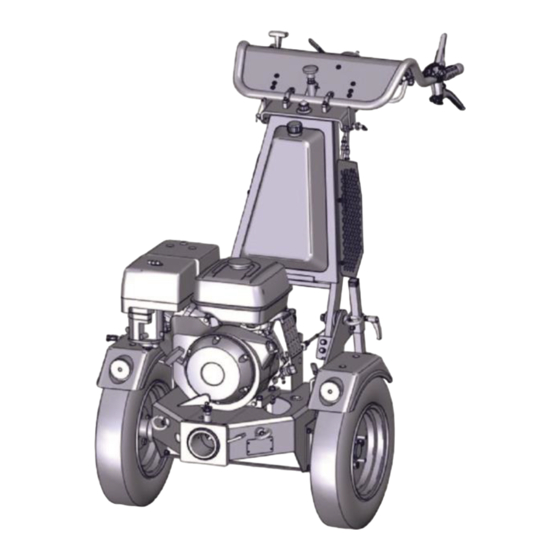
UBS Hydro II Functional description Functional description Overview The hydrostatic one-axle host vehicle is used for the following tasks. • Mowing and mulching • Snow clearing • Gritting • Removing of weeds • Sweeping • Removing of leafs • Caring of artificial lawn Fig. - Page 23 UBS Hydro II Functional description A combustion engine (1) is installed on the frame. It drives the following components: • Hydraulic pump (6) for the travel drive of the wheels • Mechanically shiftable auxiliary drive (power take-off shaft) (5) The hydraulic pump (6) provides for the circulation of hydraulic oil. The system is supplied with hydraulic oil by a central oil tank (3).
-
Page 24: Transport, Packaging And Storage
UBS Hydro II Transport, Packaging and storage Transport, Packaging and storage Mounting, installation and initial commissioning are done only by the employees of the seller or by a person authorised by it. Still, it can happen that during the installation and further use, the operators or maintenance staff of the operator are assigned the task of handling the packages. -
Page 25: Transport Of The Machine
UBS Hydro II Transport, Packaging and storage Transport of the machine Usually, the machine is transported together with the required host vehicle. NOTE Material damage due to improper handling! Improper handling of the machine can lead to damages. • Do not tilt the machine or rotate it around the horizontal axes. - Page 26 UBS Hydro II Transport, Packaging and storage Fig. 4: Transport of the machine Anchor points For the transport of the machine use the provided lifting eyes (1) of the one-axle tractor and the existing attachments. Only use functional lifting tackle in safety- related good order and condition and with sufficient load capacity.
-
Page 27: Assembly/Set Up, Installation, First Commissioning
UBS Hydro II Assembly/set up, installation, first commissioning Assembly/set up, installation, first commissioning Safety instructions Please strictly observe all safety instructions listed in the chapter Safety! (See chapter 2 Safety on page 7) Assembly of attachments Fig. 5: Assembly of attachment... -
Page 28: Assembly Of Grid Wheels (Optional)
UBS Hydro II Assembly/set up, installation, first commissioning • During assembly, definitely make sure that the coupling cam (3) is in one of the two halves of the coupling. • Pull the locking lever (1) up and turn the lever up. - Page 29 UBS Hydro II Assembly/set up, installation, first commissioning To mount the set of grid wheels carry out the following steps: • Lift the rear part of the self-propelled working machine with the appropriate tools to a height that the driving wheels are released and freely moveable.
-
Page 30: Operation
UBS Hydro II Operation Operation Safety instructions Please strictly observe all safety instructions listed in the chapter Safety! (See chapter 2 Safety on page 7) Starting the engine DANGER Danger to life or risk of injury due to escaping flue gases in confined... -
Page 31: Moving Off / Switching On The Auxiliary Drive
UBS Hydro II Operation Auxiliary drive Drive lever, right Engine switch To start the engine carry out the following steps: • Drive lever (1, 3) must be in horizontal position. • The lever for the auxiliary drive (2) must be shifted to the „Off“ position. - Page 32 UBS Hydro II Operation Before moving off, perform the following steps! • Drive lever (1, 2) must be in horizontal position. • The lever for the auxiliary drive (5) must be switched in the „Off“ position. • Push the dead man lever (3) down.
-
Page 33: Steering
UBS Hydro II Operation Steering Fig. 9: Steering with single lever and optional double lever Second steering lever left Steering lever left Dead man lever Steering lever right Second steering lever right The steering unit is designed as follows: •... -
Page 34: Switching Off Of Combustion Engine
UBS Hydro II Operation finally, the left wheel will be blocked. During this exercise, the right steering wheel is not affected and keeps its speed. In case of the optional double lever, it is possible, if required, by changing from the first steering lever to the second steering lever (1), to move the left wheel in reverse direction;... - Page 35 UBS Hydro II Operation Fig. 10: Operating Unit Drive lever Drive lever Ignition key Auxiliary drive Gas handle Engine switch To switch off the engine, carry out the following steps: • Before switching off the engine, make sure that the drive levers (1 and 2) are in horizontal position and the lever of the auxiliary drive (4) is in its “Off”...
-
Page 36: Tilting Of Steering Bar
UBS Hydro II Operation Tilting of steering bar Fig. 11: Steering bar tilted to the rear or the front Fig. 12: Locking device - steering bar Locking bolt 2018-05-02 36 / 60... -
Page 37: Tilting Of The Operating Panel
UBS Hydro II Operation The tilting angle of the steering bar can be adjusted to ensure the ergonomically optimum operating height for the operator. Furthermore, this adjustment makes it possible to set the steering bar in its vertical position to minimise the dimensions for transport. -
Page 38: Swivel The Operating Unit To The Side
UBS Hydro II Operation Swivel the operating unit to the side Fig. 14: Swivel the operating unit to the side Locking bolt The operating unit can be swivelled out of its normal position (central position) by approx. 30° to the left or the right side. -
Page 39: Maintenance
UBS Hydro II Maintenance Maintenance Safety instructions Please strictly observe all safety instructions listed in the chapter Safety! (See chapter 2 Safety on page 7) Spare parts Incorrect spare parts DANGER Risk to life or risk of injury due to the use of incorrect spare parts! This symbol warns against an immediate risk to the life and health of persons. -
Page 40: Daily Check
UBS Hydro II Maintenance Guards (coverings) Interval When the machine is put into service, is switched on Test scope Visual inspection for integrity Tester Operating personnel • Measures to Cordon off the danger zone be taken in Repair case errors... -
Page 41: Maintenance After 20 Operating Hours / Longer Down-Time
UBS Hydro II Maintenance • Check the hydraulic connections and lines for tightness and damages. • Check the air pressure of the driving wheels. • Before each use, perform a test run. • Clean the machine after each use. 7.3.3... -
Page 42: Maintenance After 100 Operating Hours / Longer Down-Time
UBS Hydro II Maintenance 7.3.4 Maintenance after 100 operating hours / longer down-time DANGER Danger to life or risk of injury due to a running machine! A running machine can cause danger to life or risk of injury, as well as risk of material damages to the machine or system! •... -
Page 43: Check The Belt Drive Of The Auxiliary Drive
UBS Hydro II Maintenance Check the belt drive of the auxiliary drive To prevent the drive belt from slipping through and following burning, the drive belts must be sufficiently tensioned when the auxiliary drive is switched on. Fig. 15: Inspection window at the rear of the one-axle carrier vehicle The tension of the drive belts can be checked through an inspection window on the rear side of the one-axle carrier vehicle. - Page 44 UBS Hydro II Maintenance Fig. 16: Tensioning device for the belt drive The belt tension is changed by releasing or tightening of a self-locking hexagon nut. The self-locking hexagon nut is accessible using a socket wrench. The socket wrench is guide through the housing opening on the side and is set onto the self- locking hexagon nut.
-
Page 45: Maintenance Of Wearing Bush
UBS Hydro II Maintenance Maintenance of wearing bush Fig. 17: Grease nipple Wearing bushes are installed to protect moving components from wearing caused by friction. The wearing bush installed here is lubricated through a lubrication nipple (1). Due to the environmental conditions, the wearing bush is subject to wearing. -
Page 46: Measures After Maintenance Is Done
UBS Hydro II Maintenance Measures after maintenance is done Personnel: • Private and commercial users Carry out the following steps after completing the maintenance work and switching on the machine: Check all the screw connections which may have loosened earlier for a tight fit. -
Page 47: Faults / Fault Removal
UBS Hydro II Faults / fault removal Faults / fault removal This section describes the possible causes of faults and the steps for removing them. In case of faults that occur repeatedly, reduce the maintenance intervals according to the actual load. - Page 48 UBS Hydro II Faults / fault removal Fault Possible causes Remedy fastening Firmly plug the spark-plug terminal on the spark plug Fuel line is plugged or fuel is bad Replace fuel filter or fill in fresh fuel Ventilation in the fuel tank cap...
-
Page 49: Error List E-Start Equipment
UBS Hydro II Faults / fault removal Error list E-Start equipment Fault Possible causes Remedy E-starter does not work Battery empty Charge battery or replace it Fuse defective Replace fuse Defect on cable harness, E-starter Check cable harness and E-starter... -
Page 50: Error List - Drive Line
UBS Hydro II Faults / fault removal Error list - drive line Fault Possible causes Remedy V-belts slip V-belt tension too low because Adjust the stroke of the Bowden cable pretension is not sufficient Flanks of the V-belts are hard and... -
Page 51: Dismantling, Disposal
UBS Hydro II Dismantling, disposal Dismantling, disposal Safety instructions Please strictly observe all safety instructions listed in the chapter Safety! (See chapter 2 Safety on page 7) Dismantling Before starting the dismantling: • Switch off the machine and safeguard it against a restart. - Page 52 UBS Hydro II Dismantling, disposal Batteries and accumulators CAUTION Environmental damage due to batteries and accumulators! Components of batteries and accumulators are toxic and represent a hazard for the environment. • Never throw away batteries and accumulators in the household waste and dispose them only according to the regulations applicable at the place of use.
-
Page 53: Technical Data
UBS Hydro II Technical data Technical data 10.1 General Unit Type UBS Hydro II Hydraulic oil tank litres Hydraulic oil Bio hydraulic oil based on synthetic ester Avia Syntofluid N68 (recommended) Class of viscosity as per VG 68 Max. operating pressure Delivery rate - pump approx. -
Page 54: Types Of Engine
UBS Hydro II Technical data 10.2 Types of engine UBS Hydro II 13 Unit Engine Honda, top-controlled four-cycle one- cylinder engine Net generation 11.7 Max. torque at specified 26.5 speed 2,500 Cubic capacity Maximum idle speed 3,000 Spark plug E.g. NGK BPR 6 ES Engine oil (recommended approx. - Page 55 UBS Hydro II Technical data UBS Hydro II 14 Unit Engine Briggs & Stratton Vanguard four-cycle one-cylinder engine Gross output 10.4 Max. torque at specified 32.5 speed 2,400 Cubic capacity Maximum idle speed 3,300 Spark plug Bosch FR8DC Champion RC12YC Engine oil (recommended approx.
- Page 56 UBS Hydro II Technical data UBS Hydro II 16 Unit Engine Briggs & Stratton Vanguard four-cycle one-cylinder engine Gross output 11.9 Max. torque at specified speed 2,400 Cubic capacity Maximum idle speed 3,300 Spark plug Bosch FR8DC Champion RC12YC Engine oil (recommended approx.
-
Page 57: Electrical Circuit Diagrams
UBS Hydro II Technical data 10.3 Electrical circuit diagrams 10.3.1 Without battery Fig. 18: Version without battery Chassis / engine with dynamo machine Electric box with rectifier Dashboard panel / steering bar Rectifier plus-pole Rectifier minus-pole Switch on the pump... -
Page 58: 10.3.2 With Battery
UBS Hydro II Technical data 10.3.2 With battery Fig. 19: Version with battery Chassis Dynamo machine Fan / oil cooler (optional) Engine earth conductor / Stop terminal Starter Electric box Dashboard panel / steering bar Rectifier plus-pole Rectifier minus-pole Switch on the pump... -
Page 59: Declaration Of Conformity
UBS Hydro II Technical data 10.4 Declaration of conformity We, the company Kersten Arealmaschinen GmbH Empeler Straße 95 46459 Rees, Germany declare that the product UBS Hydro II complies with all applicable provisions of the Machinery Directive 2006/42/EC. The machine is also in compliance with all applicable provisions of the following EC... - Page 60 Distributed in UK by Kersten (UK) Ltd Tel. 0118 986 9253 Progress House 39 Boulton Road Reading, RG2 0NH www.kerstenuk.com - info@kerstenuk.com 2018-05-02 60 / 60...
Need help?
Do you have a question about the UBS Hydro II and is the answer not in the manual?
Questions and answers