
Related Manuals for Xtralis ADPRO 49840600

Summary of Contents for Xtralis ADPRO 49840600
- Page 1 ADPRO XO I/O Interface USB Modules by Xtralis Technical Manual March 2018 Doc. 32688_02 Software version XO 4.02...
- Page 3 ADPRO XO I/O Interface USB Module – Technical Manual Disclaimer The contents of this document are provided on an "as is" basis. No representation or warranty (either express or implied) is made as to the completeness, accuracy or reliability of the contents of this document. The manufacturer reserves the right to change designs or specifications without obligation and without further notice. Except as otherwise provided, all warranties, express or implied, including without limitation any implied warranties of merchantability and fitness for a particular purpose are expressly excluded. Intellectual Property and Copyright This document includes registered and unregistered trademarks. All trademarks displayed are the trademarks of their respective owners. Your use of this document does not constitute or create a license or any other right to use the name and/or trademark and/or label. This document is subject to copyright owned by Xtralis. You agree not to copy, communicate to the public, adapt, distribute, transfer, sell, modify, or publish any contents of this document without the express prior written consent of Xtralis. Trade Name Statement Xtralis, the Xtralis logo, The Sooner You Know, VESDA-E, VESDA, ICAM, ECO, OSID, HeiTel, ADPRO, IntrusionTrace, LoiterTrace, ClientTrace, SmokeTrace, XOa, XOh, iTrace, iCommand, iRespond, iCommission, iPIR, and FMST are trademarks and/or registered trademarks of Xtralis and/or its subsidiaries in the United States and/or other countries. Other brand names mentioned herein are for identification purposes only and may be trademarks of their respective holder(s). General Warning This product must only be installed, configured and used strictly in accordance with the General Terms and Conditions, User Manual and product documents available from Xtralis. All proper health and safety precautions must be taken during the installation, commissioning, and maintenance of the product. The system should not be connected to a power source until all the components have been installed. Proper safety precautions must be taken during tests and maintenance of the products when these are still connected to the power source. Failure to do so or tampering with the electronics inside the products can result in an electric shock causing injury or death and may cause equipment damage. Xtralis is not responsible and cannot be held accountable for any liability that may arise due to improper use of the equipment and/or failure to take proper precautions. Only persons trained through an Xtralis accredited training course can install, test and maintain the system. Liability You agree to install, configure, and use the products strictly in accordance with the User Manual and product documents available from Xtralis.
- Page 4 XO I/O Interface USB Module – Technical Manual ADPRO Contact Us UK and Europe +44 1442 242 330 D-A-CH +49 431 23284 1 The Americas +1 781 740 2223 Middle East +962 6 588 5622 Asia +86 21 5240 0077 Australia and New Zealand +61 3 9936 7000 www.xtralis.com Environmental Information The crossed-out wheeled bin means that within the European Union the product must be taken to separate collection at the product end of life. This applies to the device but also to any accessories marked with this symbol. Do not dispose of these products as unsorted municipal waste. If you need more information on the collection, reuse, and recycling systems please contact your local waste administration. You can also contact us for more information on the environmental specifications of our products. 32688_02...
-
Page 5: Table Of Contents
ADPRO XO I/O Interface USB Module – Technical Manual Contents About the XO I/O Interface USB Module Features Possible Configurations System Requirements Ordering Information Specifications Installation Rubber Feet Logging on to the Hardware Configuration Tool Mapping the XO I/O Interface USB Modules Resetting the Hardware Mapping Connection of Inputs and Outputs Overview of Inputs and Outputs Input Circuits Connecting Inputs and Outputs Configuring the I/O Cards Front LED Indicators 32688_02... - Page 6 XO I/O Interface USB Module – Technical Manual ADPRO 32688_02...
-
Page 7: About The Xo I/O Interface Usb Module
ADPRO XO I/O Interface USB Module – Technical Manual About the XO I/O Interface USB Module Note You can find the latest versions of this document and any referenced document on the Xtralis Security Solutions Support site www.xtralissecurity.com (logon may be required). If a document number is indicated (between parentheses), you can enter it in the Keywords box on the site, and search for the document. Features The XO I/O Interface USB modules contain sets of Main I/O and Extension I/O cards (Next Generation) that you can connect to your XO device via USB for extra inputs and outputs. You do not need to build the cards into the device itself. The following models exist: Single module. Contains one set of I/O cards: one Main I/O (MIO) and one Extension I/O (EIO) card. Double module. Contains two sets of I/O cards: 2 x (MIO + EIO). XO I/O Interface USB module: Rear view, single module: Rear view, double module: The modules offer: Extra inputs and outputs: Single module: 20 tamper-protected inputs and 8 relay outputs (rated 14 VDC @ 1 A) ... -
Page 8: Possible Configurations
If you already have 1 MIO card built into your XO device, you can only use the single module as a secondary set of MIO/EIO cards. If you already have 2 MIO cards built into your XO device, you cannot use any modules. Note Because FastTrace 2 Series and iFT Series devices typically have at least one MIO card built in, only the single module is suitable, as a second set of MIO/EIO cards. The double module is for future applications. You have to map the modules to the correct card set (MIO-1 or MIO-2) using the hardware configuration tool. If not, the XO device will not discover the cards and you will not be able to use the inputs/outputs. Furthermore, if you are using adapters on the USB ports of your XO device (to connect to PIR detectors or for PTZ control of analogue cameras), you also have to map these 'devices' using the hardware configuration tool. If the system detects a mismatch between the items configured in the hardware configuration tool and the hardware that the system has detected (either more or less than configured), the system will activate system input 0002 – [SYST] – HW CFG MISMATCH. Note Although it is technically possible to disable an existing, built-in MIO/EIO card in the hardware configuration tool, and use an external module instead, Xtralis recommends to keep and use the built- in cards. If you disable a built-in MIO card, you have to switch off the buzzer and watchdog features, or the system will beep continuously. Switching off the buzzer and watchdog seriously reduces the system's reliability and security. System Requirements To connect and install the XO I/O Interface USB modules, you need: An XO device running firmware version XO 4.00 or above. For the single module: 1 free USB port on the XO device. For the double module: 2 free USB ports on the XO device. Ordering Information Use these reference numbers to place your order with Xtralis: Item Reference number Single module: XO I/O Interface USB Module, 49840600 1 x (MIO + EIO) -
Page 9: Specifications
ADPRO XO I/O Interface USB Module – Technical Manual The XO I/O Interface USB modules include rubber feet, EOL resistor sets, and USB cables. Specifications Power supply Single module: 1 x 5 V from USB Double module: 2 x 5 V from USB Operating temperature 0–40 °C Relative humidity 20–93 % (non-condensing) Housing dimensions 220 x 44 x 160 mm (W x H x D) 32688_02... -
Page 10: Installation
XO I/O Interface USB Module – Technical Manual ADPRO Installation Rubber Feet Attach the included self-adhesive rubber feet to the bottom of the module. Logging on to the Hardware Configuration Tool You need to log on to the hardware configuration tool using the XO Technician user. For this, you need to: 1. Enable the Technician user using the XO client software. 2. Generate a special, temporary access code (PIN of the day) for the Technician user. The PIN limits the time that the Technician user has access to the configuration tool. Note You cannot log on to the hardware configuration tool while the XO device is restarting. To log on to the hardware configuration tool, proceed as follows: 1. Open the XO client, and log on to the desired XO device as an Administrator. 2. Choose System > General > Users. 3. Under Technician grant, click Enable. 4. Under Technician pin of the day code, click Pin of the day. The following window appears: 32688_02... - Page 11 ADPRO XO I/O Interface USB Module – Technical Manual 5. In the Validity box, enter the time (in minutes) that the PIN has to remain valid. The maximum time is 1440 minutes = 24 h. 6. Click Create. A new PIN appears under Current pin of the day. The counter in the Remaining Validity (min) box displays for how long (in minutes) the new code is still valid. 7. Write down the code (including the dashes), or keep the window open and move it to where you will be able to see it while logging on to the hardware configuration tool. 8. Open Internet Explorer, and type the following url in the address bar: http://ipaddress:controlport/login where ipaddress is the XO device’s IP address and controlport is the control port number. For example, with the default IP address and control port: http://10.0.0.10:2000/login The following screen appears: 9. Type the username (15) and password (default is 666777) for the Technician user, and click Login. The following screen appears: Note If the Login window appears again, check in the XO client software if the Technician user is enabled.
- Page 12 XO I/O Interface USB Module – Technical Manual ADPRO 10. In the Pin of the day box, type the code that you noted down in step 7. Include the dashes. 11. Click Enter. The hardware configuration screen appears: Note If the Pin of the day window appears again, you have entered an invalid PIN code. 32688_02...
-
Page 13: Mapping The Xo I/O Interface Usb Modules
ADPRO XO I/O Interface USB Module – Technical Manual Mapping the XO I/O Interface USB Modules The Usb ports list in the hardware configuration tool shows the currently configured USB ports (Device node column) on the XO device. The example screen above displays, from top to bottom: On USB port 3 (ttyU3): a USB adapter for PTZ control of an analogue camera. The MIO card of the first set (MIO-1). Internally, the mapping of MIO and EIO cards on an XO device is as follows: Set number I/O card Device node MIO-1 MIO card 1 ttyU6 EIO card 1 ttyU5 MIO-2 MIO card 2 ttyU8 EIO card 2 ttyU7... - Page 14 XO I/O Interface USB Module – Technical Manual ADPRO To connect and map the XO I/O Interface USB modules, proceed as follows: 1. If you have not done so already, log on to the hardware configuration tool. 2. Connect the XO I/O Interface USB module to the XO device using the provided USB cable: insert one end into the module, and the other end into a free USB port on the XO device. Note If you are using a double module, Xtralis recommends to connect and map each module separately. Because the modules all appear with the same name in the Product column (MIO CARD), this will prevent incorrect mapping. 3. In the hardware configuration tool, click Refresh. The module will now appear in the list, with the Device Node column empty. The example below shows a device that already has a first set of MIO/EIO cards: MIO-1 is already configured. The row above (- - -) indicates the newly connected module that needs to be mapped. 32688_02...
- Page 15 ADPRO XO I/O Interface USB Module – Technical Manual 4. Select the desired set number for the module in the Device Node column. 5. Click Apply Configuration. The message Are you sure to apply your configuration? appears. 6. Click Apply. The Waiting to apply… message appears. 7. Wait for the message to disappear. 8. If you are mapping a double module, repeat for the second module: connect it to the XO device using the USB cable, click Refresh in the configuration tool, and map the module to the correct set number. 9. If the Product columns shows any other devices (in the example screen above, the FT232 USB Serial = an RS-485-to-USB converter), make sure that these devices are also mapped to a suitable USB port. 10. ...
-
Page 16: Resetting The Hardware Mapping
XO I/O Interface USB Module – Technical Manual ADPRO Resetting the Hardware Mapping When you use XO I/O Interface USB modules, the system reconfigures the USB ports and they no longer have the default numbering as described in the hardware manuals. If you have removed all the XO I/O Interface USB modules from your XO device, you can reset the USB port configuration back to the defaults. To reset the USB port configuration, proceed as follows: 1. Unplug all XO I/O Interface USB modules from your XO device. 2. Log on to the hardware tool. 3. On the Hardware Configuration tab, click Refresh. This will remove any XO I/O Interface USB modules from the hardware list. 4. In the menu at the top, click Reset configuration. 5. Click Reset. The following message appears: 6. Click Apply to confirm. The system will reset the USB port numbering to the default values, and restart the XO device. 7. You no longer need the hardware configuration tool: you can close it. Caution! Do not use the hardware configuration tool after resetting, unless you want to add XO I/O ... -
Page 17: Connection Of Inputs And Outputs
ADPRO XO I/O Interface USB Module – Technical Manual Connection of Inputs and Outputs Overview of Inputs and Outputs The image below shows the inputs and outputs on a double module. On a single module, only the inputs and outputs on the left are available: IN1–20 are voltage-free contact inputs. Each input has its own GND. C1–8 are voltage-free relay contact outputs. Each output has a common terminal (C1–C8) and both a normal open (NO1–NO8) and normal closed (NC1–NC8) terminal. Use the appropriate terminal for each output. Do not use both NO and NC terminals for the same output. The connectors labelled N.U. are not used. Input Circuits Below are the NEOL, SEOL, and DEOL configurations for the inputs. For correct operation, you also have to indicate the used input circuit configuration in the XO client software. For more information, see the XO Client Software User Manual (21796). Normally open – NEOL Normally open – SEOL Short circuit = alarm Short circuit = alarm Open circuit = idle 1K1 = idle (Default setting) Open circuit = tamper Normally closed – NEOL... -
Page 18: Connecting Inputs And Outputs
XO I/O Interface USB Module – Technical Manual ADPRO Connecting Inputs and Outputs Depending on the type, the I/O card can be equipped with Dinkle (standard) or Phoenix spring insertion connectors. For both types you need a 2 mm slotted screwdriver. Warning! Although the picture below shows only the connector, it is strongly recommended to connect the wires with the connectors plugged into the card. Wiring a handheld connector may cause injuries. Wiring to Dinkle and Phoenix connectors is identical, except that the position of tabs and holes is swapped. The picture in the procedure below shows a Phoenix connector. To connect inputs and outputs, proceed as follows: 1. Push the slotted tab firmly inwards with the screwdriver. 2. Insert the stripped wire (6–7 mm) into the corresponding round hole as deeply as possible. 3. Release the tab and pull the wire to check if it is properly fitted. Wire gauge: Solid and stranded: 16–24 AWG (diam. 1.3–0.5 mm) Configuring the I/O Cards The XO devices do not automatically detect the connected XO I/O Interface USB modules. You must set up the modules using the hardware configuration tool first. For details, see Mapping the XO I/O Interface USB Modules on page 13. After correctly setting up the hardware, you can configure the inputs and outputs in the XO client ... -
Page 19: Front Led Indicators
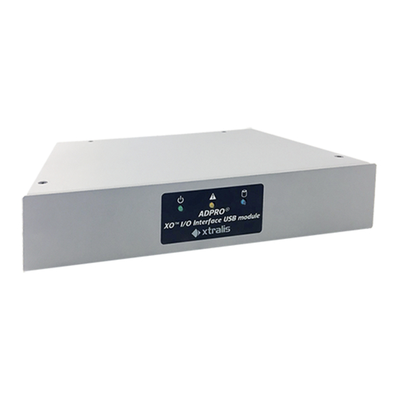
ADPRO XO I/O Interface USB Module – Technical Manual Front LED Indicators If you are using a single module as an extension on an ADPRO device of the FastTrace 2 Series or iFT Series, with a built-in MIO card, then the LEDs on the XO I/O Interface USB module follow the LEDs on the front of the ADPRO device. Icon Description Green LED Indicates that power is on. The green LED periodically blinks (goes out briefly). This is normal behaviour. Yellow LED Indicates a fault. If the yellow LED lights up, check the status of your device. For more information, see the XO Client Software User Manual (21796). Blue LED Indicates storage media activity. Caution! When the 3 LEDs are flashing simultaneously, the system is servicing the recording disks (upgrading, formatting…). In that case, do not turn off power. 32688_02... - Page 20 XO I/O Interface USB Module – Technical Manual ADPRO 32688_02...
- Page 22 UK and Europe +44 1442 242 330 D-A-CH +49 431 23284 1 The Americas +1 781 740 2223 Middle East +962 6 588 5622 Asia +86 21 5240 0077 Australia and New Zealand +61 3 9936 7000 A Disclaimer about this document, statements about Intellectual Property, Copyrights, and Liability, as well as a General Warning are available in an earlier section of this document.
Need help?
Do you have a question about the ADPRO 49840600 and is the answer not in the manual?
Questions and answers