Table of Contents
Advertisement
Quick Links
RS-232/RS-485 Synchronous
Multipoint Line Driver (LD485S-MP)
CUSTOMER
SUPPORT
INFORMATION
L D 4 8 5 S - M P
Order toll-free in the U.S. 24 hours, 7 A.M. Monday to midnight Friday: 877-877-BBOX
FREE technical support, 24 hours a day, 7 days a week: Call 724-746-5500 or fax 724-746-0746
Mail order: Black Box Corporation, 1000 Park Drive, Lawrence, PA 15055-1018
Web site: www.blackbox.com • E-mail: info@blackbox.com
R T S C D T
T E S T
D L B L L B
AUGUST 1999
ME742A-R3
ME742C-R3
BC00703
FA520A-R2
P W R
D R D
Advertisement
Table of Contents

Subscribe to Our Youtube Channel
Related Manuals for Black Box LD485S-MP


Summary of Contents for Black Box LD485S-MP
- Page 1 Order toll-free in the U.S. 24 hours, 7 A.M. Monday to midnight Friday: 877-877-BBOX SUPPORT FREE technical support, 24 hours a day, 7 days a week: Call 724-746-5500 or fax 724-746-0746 INFORMATION Mail order: Black Box Corporation, 1000 Park Drive, Lawrence, PA 15055-1018 Web site: www.blackbox.com • E-mail: info@blackbox.com...
- Page 2 TRADEMARKS TRADEMARKS USED IN THIS MANUAL Any trademarks used in this manual are acknowledged to be the property of the trademark owners.
- Page 3 LD485S-MP FEDERAL COMMUNICATIONS COMMISSION CANADIAN DEPARTMENT OF COMMUNICATIONS RADIO FREQUENCY INTERFERENCE STATEMENTS This equipment generates, uses, and can radiate radio frequency energy and if not installed and used properly, that is, in strict accordance with the manufacturer’s instructions, may cause interference to radio communication. It has been tested...
- Page 4 NOM STATEMENT NORMAS OFICIALES MEXICANAS (NOM) ELECTRICAL SAFETY STATEMENT INSTRUCCIONES DE SEGURIDAD 1. Todas las instrucciones de seguridad y operación deberán ser leídas antes de que el aparato eléctrico sea operado. 2. Las instrucciones de seguridad y operación deberán ser guardadas para referencia futura.
- Page 5 LD485S-MP 12. Precaución debe ser tomada de tal manera que la tierra fisica y la polarización del equipo no sea eliminada. 13. Los cables de la fuente de poder deben ser guiados de tal manera que no sean pisados ni pellizcados por objetos colocados sobre o contra ellos, poniendo particular atención a los contactos y receptáculos donde salen del...
-
Page 6: Table Of Contents
CONTENTS Contents Section Page 1. Specifications ......................6 2. Introduction ......................9 Application ....................10 Front-Panel Indicators and Buttons............11 Back-Panel Connectors ................12 3. Configuration ......................13 Switches ......................15 3.1.1 Baud Rate ....................15 3.1.2 Transmit Data Clock ................16 3.1.3 Node Termination (Switch 7) ............17 Jumpers ......................17 3.2.1 Constant Carriers or Switched Modes ..........17 3.2.2 RTS/CTS Delay ..................18 3.2.3 Full or Half-Duplex Operation ............19... -
Page 7: Specifications
LD485S-MP 1. Specifications EIA RS-232-C (CCITT V.24/V.28) configured as DCE Terminal Interface — serial synchronous internal/external/recovered TX data clock EIA RS-485 twisted pair (26 AWG minimum), DC Line Interface — continuity required Data Rates — 1200, 2400, 4800, 9600, 19,200, 38,400, 56,000, 64,000, 112,000, or 128,000 bps Operating Modes —... - Page 8 CHAPTER 1: Specifications Transmission Distance — (4-wire point-to-point, 26-AWG twisted pair) Speed (bps) Distance 1200 4 miles (6.4 km) 2400 3 miles (4.8 km) 4800 2.3 miles (3.68 km) 9600 1.7 miles (2.72 km) 19,200 1.2 miles (1.92 km) 38,400 0.9 mile (1.44 km) 56,000 0.8 mile (1.28 km)
- Page 9 LD485S-MP RS-232-C Name Protective Ground (FG) Transmit Data (TD) Receive Data (RD) Request To Send (RTS) Clear To Send (CTS) Data Set Ready (DSR) Signal Ground (SG) Receive Line Signal Detector (CD) Aux + power (+12V through 560 ohms) Aux - power (-12V through 560 ohms)
-
Page 10: Introduction
CHAPTER 2: Introduction 2. Introduction The RS-232 Synchronous Multipoint Line Driver provides short-haul synchronous data communication over customer-owned twisted-pair cable. It’s available as a standalone unit (Part Number ME742A-R3) or a rackmount card (Part Number ME742C-R3). The rackmount version is functionally identical to the standalone unit, but it fits in a rackmount chassis that holds up to 16 cards. -
Page 11: Application
LD485S-MP 2.1 Application Two or more Line Drivers can be set up for point-to-point or multipoint applications as shown in Figures 2-1 and 2-2. A multidrop network can accommodate up to 64 devices. 2- or 4-wire Cable IBM 3274 IBM Mainframe Controller Figure 2-1. -
Page 12: Front-Panel Indicators And Buttons
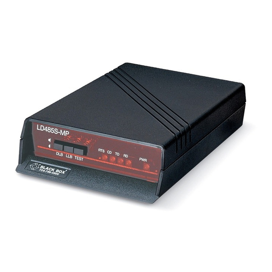
CHAPTER 2: Introduction 2.2 Front-Panel Indicators and Buttons The front panel of the RS-232 Synchronous Multipoint Line Driver has five status indicators (LEDs) as follows: Will light when data is transmitted by the local attached RS-232 device (pin 2 is active). Will toggle as data is received from the remote RS-232 device (pin 3 is active). -
Page 13: Back-Panel Connectors
LD485S-MP 2.3 Back-Panel Connectors Two connectors are located on the LD485S’s rear panel: • One DB25 female connector, configured as DCE; connects the line driver to an RS-232 DTE device. • One 4-screw terminal block: for RS-485 communication between two or more... -
Page 14: Configuration
CHAPTER 3: Configuration 3. Configuration Before you install the Line Driver, configure it to work in your application. Figure 3-2 shows a layout of the printed circuit board and the location of the jumpers and switches. Each option is discussed in detail in Sections 3.1 and 3.2. 4-WIRE CONNECTIONS (FULL DUPLEX) TX-A... - Page 15 LD485S-MP BAUD RATE SETTINGS TRANSMIT CLOCK SELECT Constant Carrier 0ms RTS/CTS 11ms 50ms 160ms SWITCH MODE-JUMPER IN ONE OF FIVE RTS/CTS DELAY POSITIONS Figure 3-2. Printed Circuit Board Layout.
-
Page 16: Switches
CHAPTER 3: Configuration 3.1 Switches Three options are user-configurable via the internal switches: • Baud rate • Transmit data clock • Node termination 3.1.1 B Ten switch-selectable data rates are available: 1200, 2400, 4800, 9600 (factory setting), 19,200, 38,400, 56,000, 64,000, 112,000, or 128,000 bps. The maximum transmission distance is dependent on the data rate selected. -
Page 17: Transmit Data Clock
LD485S-MP 3.1.2 T RANSMIT LOCK Data timing is synchronized among all connected devices in one of three ways: • Internal Clock (factory setting) • Recovered Clock • External Clock Internal Clock — Line Driver generates transmit data clock and presents clock to attached DTE via Pin 15. -
Page 18: Node Termination (Switch 7)
CHAPTER 3: Configuration 3.1.3 N ERMINATION WITCH You can select whether or not the termination network for the receiver is connected to the line. Terminating the devices on the extreme ends of the line reduces distortion and improves overall signal quality in most applications. The factory setting is with Switch 7 in the TERM position. -
Page 19: Rts/Cts Delay
LD485S-MP NOTE Constant Carrier Mode pertains to full duplex or simplex operation only. Half duplex does not apply since the RTS signal is constantly held high in this mode, preventing any other signals from being raised in the sequential fashion required by half duplex operation. -
Page 20: Full Or Half-Duplex Operation
CHAPTER 3: Configuration RTS/CTS Delay Options (Jumper W2) • Constant carrier • 0 msec (no delay) • 11-msec delay (factory setting) • 50-msec delay • 160-msec delay 3.2.3 F ULL OR UPLEX PERATION Figure 3-2 shows the location of Jumper W3. This jumper allows you to select 2- or 4-wire operation. -
Page 21: Installation
LD485S-MP 4. Installation 1. Make sure the Line Driver is configured to suit your particular application. Chapter 3 describes the options available for each jumper and switch. 2. To verify that the Line Driver is functioning correctly, power on the unit and perform the Line Loopback Test (see Chapter 5). -
Page 22: Test Modes
CHAPTER 5: Test Modes 5. Test Modes Test configurations are set up by using the front-panel pushbuttons. These tests should be performed when the unit is first installed or when a problem occurs. The TST pushbutton enables the line driver’s transmitter circuitry and injects marking data into the scrambled carrier bit pattern (after resetting the scrambling circuitry). - Page 23 LD485S-MP PIN 2 RX A, B RS-485 DECODE RECEIVER RS-232 RS-485 PIN 3 TX A, B RS-485 ENCODE TRANSCEIVER DIGITAL LOOPBACK Figure 5-2. Digital Loopback Test. In the line loopback mode, the RS-485 receive data is not actively received and retransmitted.
- Page 24 CHAPTER 5: Test Modes • Incorrect RS-485 connections. The TXA lead of the local unit should be wired to the RXA lead of the remote unit. The TXB lead of the local unit should be wired to the RXB lead of the remote unit. The RXA lead of the local unit should be wired to the TXA lead of the remote unit.
- Page 25 © Copyright 1999. Black Box Corporation. All rights reserved. 1000 Park Drive • Lawrence, PA 15055-1018 • 724-746-5500 • Fax 724-746-0746...
Need help?
Do you have a question about the LD485S-MP and is the answer not in the manual?
Questions and answers