
Related Manuals for BEKA BA317NE


Summary of Contents for BEKA BA317NE
- Page 1 BA317NE Rugged one input Ex nA and Ex tc Tachometer Issue 7 Issue: July 2019...
-
Page 2: Table Of Contents
8.2 Fault finding after commissioning 5.4 EMC 8.3 Servicing 5.5 Scale card 8.4 Routine maintenance 8.5 Guarantee 8.6 Customer comments The BA317NE is CE marked to show compliance with the European Explosive Atmospheres Directive 2014/34/EU and the European EMC Directive 2014/30/EU... - Page 3 CONTENTS CONTINUED 9. Accessories 9.1 Scale card 9.2 Tag information 9.3 Display backlight 9.4 Alarms 9.4.1 Solid state output 9.4.2 Ex nA certification 9.4.3 Configuration & adjustment 9.4.4 Alarm enable: EnbL 9.4.5 Type of alarm: tYPE 9.4.6 Setpoint adjustment: 5P1x & 5P2x 9.4.7 Alarm function: Hi .
-
Page 5: Description
Only one output option may be fitted instruction sheet supplied with each instrument. The BA317NE has been certified Ex nA and Ex tc for use in gas and dust hazardous areas by Notified Body Intertek Testing and Certification Ltd and complies with the European ATEX Directive 2014/34/EU. -
Page 6: Controls
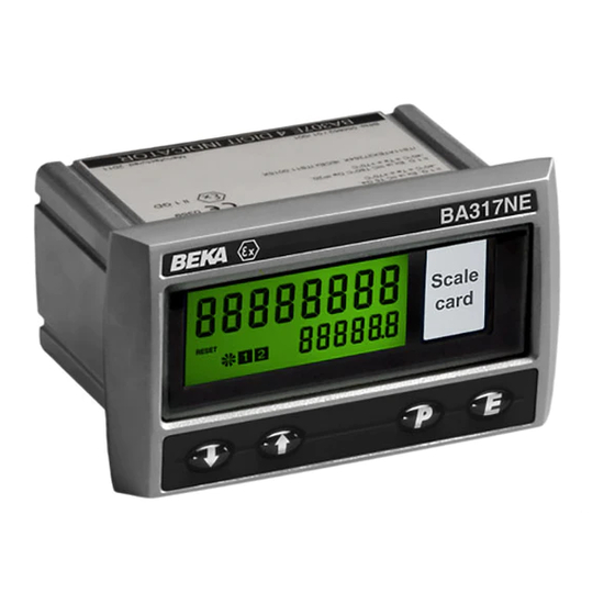
2.2 Controls 2.3 Displays The BA317NE is controlled and configured via four The BA317NE has two digital displays and front panel push buttons. In the display mode i.e. associated annunciators, plus a pulse input indicator when the instrument is displaying speed the push as shown on front cover of this manual. -
Page 7: Certification
These special conditions for safe use can be protection 'n' that minimises the risk of arcs or sparks satisfied by mounting the BA317NE in an Ex n, Ex e capable of creating an ignition hazard occurring during or Ex p panel enclosure. -
Page 8: Pulse Input
3.6 Remote reset terminals 2. The BA317NE should be powered from a The BA317NE total display my be reset to zero by circuit that has output safety parameters in connecting the external reset terminals RS1 and RS2 normal operation equal to, or less than, the together for more than one second. -
Page 9: Power Supply
2, the input terminals may be connected to a certified speed sensor located in Zone 1 as shown in 4.2 Pulse input Fig 5. The speed sensor should have Ex e or Ex d The BA317NE can display speed and run-time from a certification permitting installation... -
Page 10: Input Switching Thresholds
Any switch may be used. Fig 4 illustrates 5 & 6 providing the sensor and associated wiring can how a BA317NE may be reset from both the safe withstand a 500V rms insulation test to earth. and the hazardous area. -
Page 11: Installation
When installed in a panel enclosure complying with the requirements for Ex n protection as shown in section 3.2 of this manual, the BA317NE may be located in a Zone 2 hazardous area providing that the operating temperature is between –40°C and +60°C and the installation complies with the Tachometers certification requirements. -
Page 12: Tachometer Earthing
Tachometer rear panel. 5.3 Tachometer earthing The BA317NE has an M4 earth stud on the rear panel which should be electrically connected to the panel enclosure in which the Tachometer is mounted, or to the plant equipotential conductor. -
Page 13: Configuration And Calibration
6.1 Calibration structure will display CodE. Press ( to clear this prompt and Fig 10 shows the BA317NE calibration structure. The enter the security code for the instrument using the pulse input is divided by 5CALE. 5 to provide the &... - Page 14 6.3 Summary of configuration functions Display Summary of function This section summarises configuration functions. When read in conjunction with Fig 11 it Decimal points provides a quick aid for configuring the Tachometer. If Defines the position of the decimal more detail is required, each section contains a point in the Tachometer speed reference to a full description of the function.
- Page 15 Display Summary of function Display Summary of function Local reset Resets grand total run-time to LoC clr CLr Gtot Contains sub-menu with zero. functions enabling run-time This function resets the grand total display and grand total run-time to be run-time to zero from within the reset to zero via the front panel push configuration menu when CLr YE5 is buttons when the Tachometer is in the...
- Page 18 6.4 Input: inPut 6.6 Debounce: dEbouncE Input function contains sub-functions dEbouncE is an adjustable sub-menu in the inPut which configure function which prevents the Tachometer miscounting inP . tYPE dEbounCE Tachometer input and define the amount of input when the input pulse has noisy edges, such as those noise rejection.
-
Page 19: Position Of The Decimal Points: Dp
6.7 Display update interval: uPdAtE If the Tachometer display is likely to change rapidly, a When this digit has been adjusted as required, longer interval between display updates may simplify pressing ( will transfer control to the next digit. reading the display. This function allows one of six When all the digits have been adjusted pressing different display intervals between 0.5 and 5 seconds ( will transfer control to the decimal point which... -
Page 20: Clip-Off: Clp Off
The second digit defines the deviation from the To check or change the clip-off threshold select displayed speed at which the filtering defined by the CLP oFF from the configuration menu and press first digit will be overridden and the Tachometer speed ( which will reveal the current setting. -
Page 21: Local Grand Total Run-Time Reset: Clr Gtot
Using the & or * button select mode. clr gtot and press ( which will show if the local Please contact BEKA associates sales department if grand total reset is on or oFF. If set as required the security code is lost. -
Page 22: Configuration Example
7. CONFIGURATION EXAMPLE In this example a BA317NE Tachometer is connected Using the & or * push button select to a proximity detector producing 105 pulses per 0 . 5 (0.5 seconds i.e. 2 display updates revolution. per second). Enter the selection and... - Page 23 It is to reset the run-time display but not the recommended that the second digit is grand total run-time when the BA317NE initially set to 0. Tachometer is in the display mode. Using the & or * button select LoC clr...
- Page 24 Step 14 Reset the grand total to zero Step 16 Return to the display mode Before completing configuration the run- Configuration of the BA317NE is now time grand total should be reset to zero. complete. Pressing the ) button will Using the &...
-
Page 25: Maintenance
Incorrect speed 5cale. 5 indicator rotating display calibration but incorrect t-bA5E If a BA317NE fails after it has been functioning speed display correctly, the following table may help to identify the Pulse input Incorrect 5CALE . T cause of the failure. -
Page 26: Routine Maintenance
BA317NE Tachometer. 9.1 Scale card The BA317NE has a window on the right hand side of the display through which a scale card showing the units of measurement such as RPM can be viewed. -
Page 27: Display Backlight
9.3 Display backlight 9.4 Alarms The BA317NE Tachometer can be supplied with a The BA317NE can be supplied with factory fitted factory fitted backlight that produce green illumination dual, solid state, single pole alarm outputs that may enhancing display contrast and enabling the display to... - Page 28 9.4.3 Configuration and adjustment protected equipment located in Zone 1 or 2 of a When a BA317NE is supplied with alarms the hazardous area, or equipment located in a safe area. configuration menu is extended as shown in...
-
Page 29: Alarm Enable: Enbl
Each single pole alarm output may be open or 9.4.4 Alarm enable: EnbL closed in the non-alarm condition. When the This function allows the alarm to be enabled or BA317NE power supply turned disabled without altering any of the alarm parameters. -
Page 31: Hysteresis: H5Tr
9.4.9 Hysteresis: H5tr To adjust the alarm silence time select 5iL using the Hysteresis is only available on speed alarms so the & or * push button in the selected alarm sub- H5tr function only appears in the configuration sub- menu and press ( which will reveal the existing menu when alarm tYPE has been set to 5PEEd. - Page 32 ( which will reveal the current setting. The flashing digit of the setpoint may be adjusted using Please contact BEKA associates sales department if the & or * push button and the ( button to the security code is lost.
-
Page 33: Pulse Output
9.5 Pulse output retransmitted annunciator The BA317NE can be supplied with a factory fitted instrument display shows status isolated pulse output for retransmitting pulses to other retransmitted pulse output. Annunciator activation instruments. depends upon the setting of 5ource in the pulse output configuration menu. -
Page 34: Pulse Output Configuration
9.5.2 Pulse output configuration: PuL5E oP EN 60079-14 Electrical installations design, selection When the BA317NE Tachometer is supplied with a and erection, each of the wires entering the factory fitted pulse output the configuration menu is hazardous area should be individually fused and extended as shown in Fig 18 to include the pulse contain a means of isolation. -
Page 35: Divide Output Pulse Frequency: Divide
9.5.4 Source of pulse output: 5ourCE The output pulse may be derived from: Synchronously re-transmitted dirECt input pulse. Output pulse is a duplicate of the Tachometer input pulse. Input pulse scaled prior to re- 5CALEd transmission. Input pulse frequency may be divided to produce output pulse with defined... -
Page 36: Pulse Storage
Fig 19 shows a typical application in which a maximum possible speed. BA317NE Tachometer is mounted in an Ex n panel enclosure located in Zone 2 is retransmitting the When the total display is reset to zero or the power 4/20mA current to the safe area. -
Page 37: Configuration
9.6.2 Configuration 9.6.4 Enable 4/20mA output: EnbL When a Tachometer is supplied with an optional This function allows the 4/20mA output to be 4/20mA output the configuration menu is extended as disabled or enabled without altering any of the shown in Fig 20. The 4/20mA output sub-menu is 4/20mA output parameters. - Page 38 'X' suffix to show that special conditions for In addition to ATEX Ex nA certification permitting safe use are specified by the BA317NE Ex ic tc installation in explosive gas atmospheres which is certificate indicated by the certificate number's 'X' described in the main section of this instruction suffix.
- Page 39 For additional information about the IECEx certification scheme and to view the BEKA associate certificates, please visit www.iecex.com A2.1 IECEx Certificate of Conformity The BA317NE Tachometer has been issued with an IECEx Certificate Conformity number IECEx ITS 16.0005X which specifies the following certification code: Ex nA ic IIC T5 Gc -40ºC ≤...
- Page 40 USA and Canada A3.0 cETL Mark For installations in the USA and Canada, the BA317NE Tachometer has ETL and cETL Ex nA and Ex tc approval, Control Number 4008610. Copies of the Authorisation to Mark are available from the BEKA associates sales office and www.beka.co.uk...
Need help?
Do you have a question about the BA317NE and is the answer not in the manual?
Questions and answers