Table of Contents
Advertisement
Quick Links
Advertisement
Table of Contents

Summary of Contents for IDS RIS Hi-Mod
- Page 1 - PRO/010/M1 Rev 4 - INGEGNERIA DEI SISTEMI S.p.A. Rev. 1.1 N. doc.: MN/2009/056 RIS Hi-Mod / DUALF-400-900 Systems Installation Guide and User Manual RIS Hi-Mod / DUALF-400-900 - Installation Guide and User Manual Pisa, December 2010 Tot pag. N°. =...
- Page 2 IDS Ingegneria Dei Sistemi S.p.A. N. doc.: MN/2009/056 - Rev. 1.1 RIS Hi-Mod / DUALF-400-900 - Installation Guide and User Manual Document Evolution Revision Date Reason for change Rev. 1.0 August 2009 First edition Rev. 1.1 December 2010 Document revision. Added DUALF-400-900 and...
- Page 3 PEOPLE ANALYSIS; RATHER, THEY HAVE TO BE INTENDED AS AN ADVISOR AND THE USER MUST BE AWARE THAT THE RESULTS PROVIDED BY THEM MAY BE NOT ABSOLUTELY ERROR FREE AND MUST NOT COMPLETELY RELY ON THE RESULTS PROVIDED BY THEM. IDS ASSUMES NO LIABILITY FOR DIRECT, INDIRECT SPECIAL,...
- Page 4 IDS Ingegneria Dei Sistemi S.p.A. N. doc.: MN/2009/056 - Rev. 1.1 RIS Hi-Mod / DUALF-400-900 - Installation Guide and User Manual SAFETY INFORMATION The equipment conforms to the following requirements set by EC regulations, including subsequent modifications, and to the legislation set...
- Page 5 IDS Ingegneria Dei Sistemi S.p.A. N. doc.: MN/2009/056 - Rev. 1.1 RIS Hi-Mod / DUALF-400-900 - Installation Guide and User Manual IMPORTANT NOTE FOR THE US CUSTOMERS FCC ID: UFW-HI-MOD This device complies with part 15 of the FCC Rules: Operation is subject to the following conditions: 1.
- Page 6 IDS Ingegneria Dei Sistemi S.p.A. N. doc.: MN/2009/056 - Rev. 1.1 RIS Hi-Mod / DUALF-400-900 - Installation Guide and User Manual IMPORTANT NOTE FOR THE US CUSTOMERS FCC ID: UFW-DUALF-400-900 This device complies with part 15 of the FCC Rules: Operation is subject to the following conditions: 1.
- Page 7 IDS Ingegneria Dei Sistemi S.p.A. N. doc.: MN/2009/056 - Rev. 1.1 RIS Hi-Mod / DUALF-400-900 - Installation Guide and User Manual IMPORTANT NOTE FOR THE CANADIAN CUSTOMERS IC Certification Number: IC:8991A –HIMOD This device complies with the requirements of IC Standard RSS-220 This Ground Penetrating Radar Device shall be operated only when in contact with or within 1 m of the ground.
- Page 8 IDS Ingegneria Dei Sistemi S.p.A. N. doc.: MN/2009/056 - Rev. 1.1 RIS Hi-Mod / DUALF-400-900 - Installation Guide and User Manual BATTERIES REMOVAL INFORMATION Laptop Batteries: Manufacturer: PANASONIC Type: Li-ion Ni Characteristics: 10.65V 5.7Ah Removal instructions: 1. turn off the laptop;...
- Page 9 Separate waste disposal of this product at the end of its useful life will be organised and managed by IDS. When you decide to dispose of the equipment, contact IDS and follow the system that IDS has set up to permit the separate collection of the apparatus at its life end.
- Page 10 To proceed in the application of warranty terms, Buyer shall have to contact IDS Customer Care Office to get the clearance to return the Faulty Parts. The Faulty Parts once received by IDS will be inspected to verify they are eligible for repair or replacement..
- Page 11 IDS Ingegneria Dei Sistemi S.p.A. N. doc.: MN/2009/056 - Rev. 1.1 RIS Hi-Mod / DUALF-400-900 - Installation Guide and User Manual 3.EXCEPT AS PROVIDED IN THIS DOCUMENT, THE FOREGOING WARRANTIES ARE IN LIEU OF ALL OTHER WARRANTIES, AND SELLER MAKES NO OTHER...
-
Page 12: Table Of Contents
IDS Ingegneria Dei Sistemi S.p.A. N. doc.: MN/2009/056 - Rev. 1.1 RIS Hi-Mod / DUALF-400-900 - Installation Guide and User Manual INDEX 1. Hardware equipment of the Hi-MOD AND DUALF-400-900 systems ....15 Rudder ........................15 1.1.1 Assemblage instructions ................... 16 1.1.2 Wiring....................... - Page 13 IDS Ingegneria Dei Sistemi S.p.A. N. doc.: MN/2009/056 - Rev. 1.1 RIS Hi-Mod / DUALF-400-900 - Installation Guide and User Manual FIG. 1.10 – MAGNETIC ENCODER CABLE ..............20 FIG. 1.11 – ANTENNA CABLE IN PLACE ..............21 FIG. 1.12 – BATTERY CABLE AND LAN CABLE ............21 FIG.
- Page 14 RIS Hi-Mod / DUALF-400-900 - Installation Guide and User Manual FIG. 3.1 – MAIL SENT BY IDS TO THE CLIENT ............42 FIG. 3.2 – CLIENT DATA INSERTION FORM ............. 43 FIG. 3.3 – WEBEX SET UP WINDOW ................43 FIG.
-
Page 15: Hardware Equipment Of The Hi-Mod And Dualf-400-900 Systems
IDS Ingegneria Dei Sistemi S.p.A. N. doc.: MN/2009/056 - Rev. 1.1 RIS Hi-Mod / DUALF-400-900 - Installation Guide and User Manual 1. HARDWARE EQUIPMENT OF THE HI-MOD AND DUALF-400-900 SYSTEMS Hi-MOD and DUALF-400-900 systems offers you the possibility to choose up to four different equipments, matching the number of antennas you want to use. -
Page 16: Assemblage Instructions
IDS Ingegneria Dei Sistemi S.p.A. N. doc.: MN/2009/056 - Rev. 1.1 RIS Hi-Mod / DUALF-400-900 - Installation Guide and User Manual 1.1.1 Assemblage instructions First you have to set the rudder in its mono antenna setting. The rudder has two free bars and four knobs (Fig. - Page 17 IDS Ingegneria Dei Sistemi S.p.A. N. doc.: MN/2009/056 - Rev. 1.1 RIS Hi-Mod / DUALF-400-900 - Installation Guide and User Manual Fig. 1.3 – Rudder knobs: bigger one on the left, smaller one on the right Now you have to build the frame carrying the antenna: you will need the equipment shown in Fig.
- Page 18 IDS Ingegneria Dei Sistemi S.p.A. N. doc.: MN/2009/056 - Rev. 1.1 RIS Hi-Mod / DUALF-400-900 - Installation Guide and User Manual Fig. 1.5 – Connection pipes in position and closed frame Place the rudder into the metallic connections of the wheel frame as shown in Fig.
- Page 19 IDS Ingegneria Dei Sistemi S.p.A. N. doc.: MN/2009/056 - Rev. 1.1 RIS Hi-Mod / DUALF-400-900 - Installation Guide and User Manual Fig. 1.7 – Close up of the metallic frames (up) and locking device (down) Take the antenna and make it slide in the frame from behind. Remember to put and remove the antenna always from the rear part of the frame.
-
Page 20: Wiring
IDS Ingegneria Dei Sistemi S.p.A. N. doc.: MN/2009/056 - Rev. 1.1 RIS Hi-Mod / DUALF-400-900 - Installation Guide and User Manual Finally put the DAD Control unit inside the box in the middle of the rudder (Fig. 1.9) and the battery in one of the two small black bags Fig. - Page 21 IDS Ingegneria Dei Sistemi S.p.A. N. doc.: MN/2009/056 - Rev. 1.1 RIS Hi-Mod / DUALF-400-900 - Installation Guide and User Manual Take the Antenna cable and link the IN port of the antenna box with the ANT1/CHAIN port of the DAD unit (Fig. 1.11).
-
Page 22: Two Antennas Equipment And Configuration
IDS Ingegneria Dei Sistemi S.p.A. N. doc.: MN/2009/056 - Rev. 1.1 RIS Hi-Mod / DUALF-400-900 - Installation Guide and User Manual You can find more info about the DAD unit and its cable connectors in Chapter 2: The DAD control unit. -
Page 23: Rudder
IDS Ingegneria Dei Sistemi S.p.A. N. doc.: MN/2009/056 - Rev. 1.1 RIS Hi-Mod / DUALF-400-900 - Installation Guide and User Manual Wheeled frames Rudder Antennas Connection Pipes Battery & LAN cables Antenna cables Non- DAD unit & wheeled Batteries frame Fig. - Page 24 IDS Ingegneria Dei Sistemi S.p.A. N. doc.: MN/2009/056 - Rev. 1.1 RIS Hi-Mod / DUALF-400-900 - Installation Guide and User Manual To build the frame carrying the antennas you need the equipment shown in Fig. 1.15. Fig. 1.15 – Two Antennas frame equipment Take one of the wheeled frames and screw two connection pipes in it.
- Page 25 IDS Ingegneria Dei Sistemi S.p.A. N. doc.: MN/2009/056 - Rev. 1.1 RIS Hi-Mod / DUALF-400-900 - Installation Guide and User Manual Fig. 1.16 – Making the two antennas frame Fig. 1.17 – Insertion and locking of the rudder Take the antennas and make them slide in the frame from behind. Remember to put and remove the antennas always from the rear part of the frame.
-
Page 26: Wiring
IDS Ingegneria Dei Sistemi S.p.A. N. doc.: MN/2009/056 - Rev. 1.1 RIS Hi-Mod / DUALF-400-900 - Installation Guide and User Manual Fig. 1.18 – Insertion of the antennas and close-up of the hook Place the DAD control unit inside the box on the rudder and the batteries in the two little black bags (Fig. -
Page 27: Three Antennas Equipment And Configuration
IDS Ingegneria Dei Sistemi S.p.A. N. doc.: MN/2009/056 - Rev. 1.1 RIS Hi-Mod / DUALF-400-900 - Installation Guide and User Manual Fig. 1.20 – Antenna cables You can find more info about the DAD unit and its cable connectors in Chapter 2: The DAD control unit. -
Page 28: Assemblage Instructions
IDS Ingegneria Dei Sistemi S.p.A. N. doc.: MN/2009/056 - Rev. 1.1 RIS Hi-Mod / DUALF-400-900 - Installation Guide and User Manual Wheeled frames Rudder Antennas Antenna cables Battery & LAN cables Batteries & Connection pipes Non-wheeled frames Fig. 1.21 - Equipment provided for the three antennas configuration 1.3.1 Assemblage instructions... - Page 29 IDS Ingegneria Dei Sistemi S.p.A. N. doc.: MN/2009/056 - Rev. 1.1 RIS Hi-Mod / DUALF-400-900 - Installation Guide and User Manual Take one of the wheeled frames and screw two connection pipes in it. After that close the box using one of the non-wheeled frames as shown in Fig. 1.23.
-
Page 30: Wiring
IDS Ingegneria Dei Sistemi S.p.A. N. doc.: MN/2009/056 - Rev. 1.1 RIS Hi-Mod / DUALF-400-900 - Installation Guide and User Manual Fig. 1.25 - Insertion of one antenna and close-up of the hook 1.3.2 Wiring Battery, wheel and LAN cables are linked to the DAD control unit as in the mono antenna configuration (see Par 1.1.2 Wiring for further instruction). -
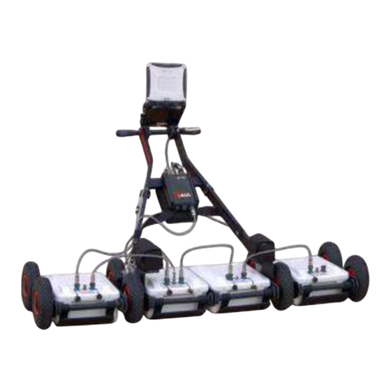
Page 31: Four Antennas Equipment And Configuration
IDS Ingegneria Dei Sistemi S.p.A. N. doc.: MN/2009/056 - Rev. 1.1 RIS Hi-Mod / DUALF-400-900 - Installation Guide and User Manual Fig. 1.27 – Three antennas configuration You can find more info about the DAD unit and its cable connectors in Chapter 2: The DAD control unit. -
Page 32: Assemblage Instructions
IDS Ingegneria Dei Sistemi S.p.A. N. doc.: MN/2009/056 - Rev. 1.1 RIS Hi-Mod / DUALF-400-900 - Installation Guide and User Manual Antennas Rudder Battery and Antenna LAN cables cables Connection pipes Batteries & DAD control unit Wheeled frames Non-wheeled frames Fig. - Page 33 IDS Ingegneria Dei Sistemi S.p.A. N. doc.: MN/2009/056 - Rev. 1.1 RIS Hi-Mod / DUALF-400-900 - Installation Guide and User Manual Fig. 1.29 – Antenna cables Fig. 1.30 – Four antennas configuration You can find more info about the DAD unit and its cable connectors in Chapter 2:...
-
Page 34: The Dad Control Unit
IDS Ingegneria Dei Sistemi S.p.A. N. doc.: MN/2009/056 - Rev. 1.1 RIS Hi-Mod / DUALF-400-900 - Installation Guide and User Manual 2. THE DAD CONTROL UNIT The DAD Control Unit is the control unit responsible for directing the antennas and digitalising the acquired radar data. - Page 35 This kind of connector may be connected to the following categories of radar antennae. Entire range of TR IDS antennae that has a 19 pole connector and foresee a cascade connection, Fig. 2-3 shows an example of a an antennae with a 19 pole connector with a cascade connection.
-
Page 36: The Notebook Computer
N. doc.: MN/2009/056 - Rev. 1.1 RIS Hi-Mod / DUALF-400-900 - Installation Guide and User Manual Entire range of TR IDS antennae that have an 11 pole connector, if supplied with an appropriate 19-11 pole adaptor (Fig. 2.4). Fig. 2.4 – 19-11 pole Adaptor 2. - Page 37 SW enter into conflict with the K2_FW acquisition SW. NOTE IDS takes no responsibility for any functional conflicts that may occur between their own software and any other software installed by the user onto the Notebook Computer. IDS doesn’t guarantee...
-
Page 38: Connecting The Dad Control Unit - Notebook Computer
IDS Ingegneria Dei Sistemi S.p.A. N. doc.: MN/2009/056 - Rev. 1.1 RIS Hi-Mod / DUALF-400-900 - Installation Guide and User Manual 2.2 Connecting the DAD Control Unit - Notebook Computer The following describes how to cable the DAD Control Unit to the Notebook Computer •... - Page 39 K2_FW software has been shut down, the indicator will flash for about 30 seconds and will automatically shut down after 2 minutes. DON’T CONNECT the Battery Cable to the Remote connector found on each IDS TR antenna; IDS declines any responsibility for WARNING damage caused to the system due to erroneous connections.
-
Page 40: Wireless Connection
IDS Ingegneria Dei Sistemi S.p.A. N. doc.: MN/2009/056 - Rev. 1.1 RIS Hi-Mod / DUALF-400-900 - Installation Guide and User Manual 2.3 Wireless connection Here below you can see the requirements and steps to connect by wireless DAD to 1) System requirement: wireless network board of PC must support network protocol type 802.11g. - Page 41 IDS Ingegneria Dei Sistemi S.p.A. N. doc.: MN/2009/056 - Rev. 1.1 RIS Hi-Mod / DUALF-400-900 - Installation Guide and User Manual Fig. 2.11 – Wireless connection on the DAD Fig. 2.12 – Configuration file for wireless connection Once the Notebook Computer has been switched on, and the start up button on the DAD unit has been pressed (a blue indicator light will be continuously lit), open the K2_FW acquisition software by clicking on the desktop icon.
-
Page 42: On Line Assistance
3.1.1 How to use the Webex service You will receive an email from IDS Customer Care containing a link to the support session (see Fig. 3.1). Fig. 3.1 – Mail sent by IDS to the client... - Page 43 IDS Ingegneria Dei Sistemi S.p.A. N. doc.: MN/2009/056 - Rev. 1.1 RIS Hi-Mod / DUALF-400-900 - Installation Guide and User Manual Once you have clicked on the link sent by email, the following window will appear. Insert your data into the form (see Fig. 3.2).
- Page 44 Chat, Video and Leave Session commands. Fig. 3.4 – Welcome to Webex Support Center window At this point, IDS Customer Care can perform a range of operations on your desktop: • Request control of the desktop using the Request Control command.
Need help?
Do you have a question about the RIS Hi-Mod and is the answer not in the manual?
Questions and answers