
Subscribe to Our Youtube Channel
Related Manuals for Motorola PMMN4125


Summary of Contents for Motorola PMMN4125
- Page 1 Remote Speaker Microphone (RSM) with 2.5 mm Connector PMMN4125_ Installation Guide OCTOBER 2019 *MN005686A01* MN005686A01-AB © 2019 Motorola Solutions, Inc. All rights reserved...
-
Page 2: Table Of Contents
MN005686A01-AB Contents Contents List of Figures......................3 List of Tables....................... 4 Copyrights........................5 Document History....................... 6 Foreword........................7 Acoustic Safety..........................7 Chapter 1: Service and Warranty................8 Warranty Exclusion........................8 Chapter 2: Important Information................9 Chapter 3: RSM Compatibility..................10 Chapter 4: Remote Speaker Microphone (RSM) Features........11 Chapter 5: Charging the Battery................12 Chapter 6: Maintenance....................13 Recommended RSM Wearing, Transmitting, and Receiving Positions........13... -
Page 3: List Of Figures
MN005686A01-AB List of Figures List of Figures Figure 1: Wearing........................... 13 Figure 2: Transmitting..........................13 Figure 3: Receiving..........................14 Figure 4: Recommended Practice......................14 Figure 5: Attaching the Connector......................14 Figure 6: Rotating the Connector......................15 Figure 7: Detaching the Connector......................15 Figure 8: Unscrewing the Back Housing....................16 Figure 9: Unscrewing the Battery Tray.................... -
Page 4: List Of Tables
MN005686A01-AB List of Tables List of Tables Table 1: RSM Features.......................... 11 Table 2: Charging Indicator Behavior..................... 12 Table 3: Replacement Parts........................23... -
Page 5: Copyrights
Motorola Solutions, Inc. Furthermore, the purchase of Motorola Solutions products shall not be deemed to grant either directly or by implication, estoppel or otherwise, any license under the copyrights, patents or patent applications of Motorola Solutions, except for the normal non-exclusive, royalty-free license to use that arises by operation of law in the sale of a product. -
Page 6: Document History
MN005686A01-AB Document History Document History Version Description Date MN005686A01-AA Initial release of the WM500 Remote Speaker April 2019 Microphone (RSM) PMMN4127_Online Installa- tion Guide manual. MN005686A01-AB Change "SL7000e, SL300, and SL3500e" to SL October 2019 Series and "TLK 100, TLK 100i, and TLK 100j" to TLK Series. -
Page 7: Foreword
MN005686A01-AB Foreword Foreword RF Energy Exposure and Product Safety Guide for Portable Two-Way Radios CAUTION: Before using this product, read the operating instructions for safe usage contained in the Product Safety and RF Exposure booklet enclosed with your radio which contains important operating instructions for safe usage and RF energy awareness and control for Compliance with applicable Standards and Regulations. -
Page 8: Chapter 1: Service And Warranty
Motorola Solutions will not honor any warranty claim where the Product is used in such a combination and it is determined by Motorola Solutions that there is no fault with the Product. Upon open or dismantle the Product, the warranty is immediately voided. Motorola Solutions specifically disclaim any responsibility for any damage in any way caused by improper installation by unauthorized personnel. -
Page 9: Chapter 2: Important Information
MN005686A01-AB Important Information Chapter 2 Important Information • Do not charge your accessory in temperature below 0°C (32°F) or above 45°C (113°F). • Do not store your accessory in direct sunlight or where expected temperatures can exceed below 0°C (32°F) or above 45°C (113°F) such as inside a parked car. •... -
Page 10: Chapter 3: Rsm Compatibility
MN005686A01-AB Chapter 3: RSM Compatibility Chapter 3 RSM Compatibility List of radio(s) or device(s) that are compatible to PMMN4125: • SL Series • SLN1000 • TLK Series... -
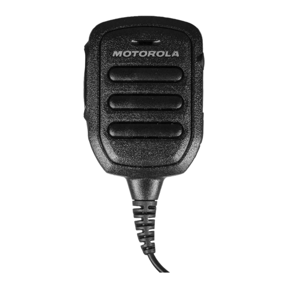
Page 11: Chapter 4: Remote Speaker Microphone (Rsm) Features
MN005686A01-AB Remote Speaker Microphone (RSM) Features Chapter 4 Remote Speaker Microphone (RSM) Features Table 1: RSM Features Label Description Charging indicator Push-to-talk button Receive-only 3.5 mm audio jack (unthreaded) covered by a dust cap Micro-USB charging port covered by a dust cap... -
Page 12: Chapter 5: Charging The Battery
MN005686A01-AB Chapter 5: Charging the Battery Chapter 5 Charging the Battery Procedure: 1 Unplug the RSM from the radio. 2 Connect the USB charging cable to the RSM. IMPORTANT: Charge the RSM immediately to prevent flat-battery condition. Table 2: Charging Indicator Behavior Indicator Description Blinking red... -
Page 13: Chapter 6: Maintenance
MN005686A01-AB Maintenance Chapter 6 Maintenance This chapter provides information about the care and maintenance of this radio. Recommended RSM Wearing, Transmitting, and Receiving Positions Figure 1: Wearing Figure 2: Transmitting... -
Page 14: Recommended Practice
MN005686A01-AB Chapter 6: Maintenance Figure 3: Receiving Recommended Practice CAUTION: Do not let the audio jack and USB charging port come in contact with water. • If water enters the audio jack and/or the USB charging port, remove the water by shaking the RSM. •... -
Page 15: Detaching The Rsm From The Radio
MN005686A01-AB Chapter 6: Maintenance 5 Rotate the connector clockwise or counter-clockwise to lock. Figure 6: Rotating the Connector 6 Turn on the radio. 7 Adjust the audio volume to a comfortable listening level. You can hear a detection tone at the accessory speaker. NOTICE: •... -
Page 16: Figure 8: Unscrewing The Back Housing
MN005686A01-AB Chapter 6: Maintenance Figure 8: Unscrewing the Back Housing 2 Unscrew the three screws from the battery tray. WARNING: Safety Critical Use a T6 torx screwdriver with 2.8 +/-0.2 lbf-in torque to remove the screws. Figure 9: Unscrewing the Battery Tray 3 Disconnect the cable connector from the molex. -
Page 17: Figure 11: Removing The Cable
MN005686A01-AB Chapter 6: Maintenance Figure 11: Removing the Cable 5 Connect the new cable, ensure that the cable orientation is correct with one hole facing out. Figure 12: Cable Orientation 6 Attach the cable connector to the molex. Figure 13: Attaching the Cable Connector 7 Reassemble the battery tray by screwing in the three screws. -
Page 18: Replacing The Battery
MN005686A01-AB Chapter 6: Maintenance Figure 14: Reassembling the Battery Tray 8 Reassemble the back housing by screwing in the four screws. WARNING: Safety Critical Use a T8 pin torx screwdriver with 3.5 +/-0.2 lbf-in torque to ensure that the screws are tightened. -
Page 19: Figure 16: Unscrewing The Back Housing
Do not use conductive or sharp tools when removing the battery. Figure 17: Removing the Battery 3 Insert the battery into the battery compartment. Attach the left side of the battery first. WARNING: Safety Critical Use only Motorola Solutions authorized BT60 Battery (HKNN4014_). -
Page 20: Figure 18: Inserting The Battery
MN005686A01-AB Chapter 6: Maintenance Figure 18: Inserting the Battery CAUTION: 1 Ensure that the battery contact is facing outward and at the top right corner. 2 Ensure that the rubber seal is securely in place. 4 Secure the battery by pressing it down. Figure 19: Securing the Battery 5 Reassemble the back housing by screwing in the four screws. -
Page 21: Figure 20: Reassembling The Back Housing
MN005686A01-AB Chapter 6: Maintenance Figure 20: Reassembling the Back Housing WARNING: Safety Critical • Do not power up the RSM and/or connect the audio jack immediately after replacing the battery. • To ensure that there are no loose elements left, shake the device gently. •... -
Page 22: Chapter 7: Optional Accessories
MN005686A01-AB Chapter 7: Optional Accessories Chapter 7 Optional Accessories • Receive-only earpiece with translucent tube (PMLN7560) • Belt clip (42009312001) Some part numbers may have regional prefix such as AA, MD, or AZ. -
Page 23: Chapter 8: Replacement Parts
MN005686A01-AB Replacement Parts Chapter 8 Replacement Parts Table 3: Replacement Parts Label Description Short Swivel Clip (4205823V01) 2.5 mm Jack Coil Cord (PMKN4224_)
Need help?
Do you have a question about the PMMN4125 and is the answer not in the manual?
Questions and answers