Table of Contents
Advertisement
Quick Links
Kehrschleifenmodul für
Loop module for digital
controlled model railways
Module de boucle de
retournement pour des
réseaux numériques
Keerlusmodule voor
digitaalsystemen
Art.-Nr. 21-01-050 C 21 03 24
Art.-Nr. 22-01-050 C 21 03 25
KSM-1
Digitalsysteme
n
n
n
n
n
n
n
n
n
n
Anleitung
n
Manual
n
Mode d´emploi
n
Handleiding
n
n
n
Advertisement
Table of Contents

Related Manuals for tams elektronik KSM-1


Summary of Contents for tams elektronik KSM-1
- Page 1 KSM-1 Kehrschleifenmodul für Digitalsysteme Loop module for digital controlled model railways Module de boucle de retournement pour des réseaux numériques Keerlusmodule voor digitaalsystemen Anleitung Manual Mode d´emploi Handleiding Art.-Nr. 21-01-050 C 21 03 24 Art.-Nr. 22-01-050 C 21 03 25...
- Page 2 © 12/2002 Tams Elektronik GmbH Alle Rechte, insbesondere das Recht der Vervielfältigung und Verbreitung sowie der Übersetzung vorbehalten. Vervielfältigungen Reproduktionen jeglicher Form bedürfen schriftlichen Genehmigung Deutsch durch die Tams Elektronik GmbH. Technische Änderungen vorbehalten. English Français © 12/2002 Tams Elektronik GmbH rights reserved.
-
Page 3: Table Of Contents
English KSM-1 Table of contents How to use this manual Intended use Safety instructions EMC declaration Operation overview Technical specifications Choosing the power supply Checking the package contents Required tools and consumables Safe and correct soldering Assembling the kit Performing a visual check... -
Page 4: How To Use This Manual
KSM-1 English How to use this manual If you have no specialist technical training, this manual gives step-by- step instructions for safe and correct assembly of the kit or fitting of the ready-built module, and operation. Before you start, we advise you to read the whole manual, particularly the chapter on safety instructions and the FAQ chapter. -
Page 5: Safety Instructions
English KSM-1 Safety instructions Mechanical hazards Cut wires can have sharp ends and can cause serious injuries. Watch out for sharp edges when you pick up the PCB. Visibly damaged parts can cause unpredictable danger. Do not use damaged parts: recycle and replace them with new ones. -
Page 6: Emc Declaration
KSM-1 English soldering station only when actually needed. Use the correct soldering iron or station and never leave a hot soldering iron or station unattended. Thermal danger A hot soldering iron or liquid solder accidentally touching your skin can cause skin burns. As a precaution: §... -
Page 7: Operation Overview
English KSM-1 § Connect the transformer only to an approved mains socket installed by an authorised electrician. § Make no changes to the original parts and accurately follow the instructions, circuit diagram and PCB layout included with this manual. §... -
Page 8: Choosing The Power Supply
KSM-1 English Ambient temperature in use 0 - + 60° C Ambient temperature in storage -10 - + 80° C Comparative humidity allowed max. 85 % Dimensions ca. 48 x 52 mm Weight ca. 20 g Choosing a power supply The module is designed for connection to 16 - 24 Volt digital supply. -
Page 9: Safe And Correct Soldering
English KSM-1 Safe and correct soldering Caution: Incorrect soldering can cause fires (through excessive heat). Avoid this danger by reading the chapter Safety instructions again and following the directions given. If you have had training in soldering you can skip this chapter. -
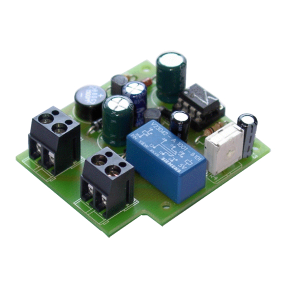
Page 10: Assembling The Kit
KSM-1 English § Cut the wires after soldering directly above the PCB solder side with a side cutter. § After placing the parts, please double check for correct polarity. Check the PCB tracks for solder bridges, short circuits created by accident. - Page 11 English KSM-1 Capacitors There is a difference between “normal” capacitors and electrolytic capacitors which have to be placed in a certain direction. They have a very bright line at one end marked with the minus (-) sign. That end must always be connected to minus.
-
Page 12: Performing A Visual Check
KSM-1 English Assembling the kit Start the assembly with the resistors and the diodes. First solder the components on the solder side of the PCB and then cut the excess wires with the side cutter as short as possible. Next solder the IC- socket, the rectifier and the transitors. -
Page 13: Functional Tests And Connection Of The Loop Module
English KSM-1 Functional test and connection of the loop module If you have purchased a ready-built module, please check all functions. Transport damage can never be excluded. Preparing and connecting the loop module Start by isolating the loop completely from the remaining circuit. Both breaks should be located as near as possible to the points. -
Page 14: Manufacturer's Note
KSM-1 English § When setting the trimming pot the relay does not switch. Possible cause: one or more components are soldered incorrectly. à Perform a visual check. Possible cause: The IC has been inserted into the IC-socket in the wrong direction. -
Page 15: Conditional Warranty
English KSM-1 Conditional warranty This product is guaranteed for two years. The warranty includes free repair if the problem is due to material failure or incorrect assembly of the ready-built module by us. Because we have no control over the assembly of the kit, we can only guarantee the quality of the components and the completeness of the kit. - Page 16 KSM-1 Stückliste - Partslist Nomenclature - Stuklijst Kondensatoren - Capacitors C1, C4 220 µF/25 V Condensateurs - Condensatoren 100 µF/25 V C3,C5 2,2 µF/25 V Dioden - Diodes - Diodes - Diodes D1, D2, D3 1N4004 * Zener-Dioden - Zener diodes...
- Page 17 KSM-1 Bestückungsplan - PCB layout Plan d´implantation - Printplan Fig. 1 n n n Seite - Page - Page - Pagina II...
-
Page 18: Connections (Fig. 2)
KSM-1 KSM-1 Anschlußplan Connections Plan de raccordement Aansluit plan Fig. 2 n n n Seite - Page - Page - Pagina III Seite - Page - Page - Pagina III... -
Page 19: Circuit Diagram (Fig. 3)
KSM-1 KSM-1 Schaltplan Circuit diagram Schéma de principe Schakelschema Fig. 3 n n n Seite - Page - Page - Pagina IV Seite - Page - Page - Pagina IV... - Page 20 Actuele informatie en tips: http://www.tams-online.de Garantie und Service: Warranty and service: Garantie et service: Garantie en service: Tams Elektronik GmbH Sievertstraße 22 D-30625 Hannover fon: ++49 (0)511 / 55 60 60 fax: ++49 (0)511 / 55 61 61 e-mail: modellbahn@tams-online.de...
Need help?
Do you have a question about the KSM-1 and is the answer not in the manual?
Questions and answers